HP AdvanceStack 10Base-T Hubs Installation and Reference Guide
©Copyright Hewlett-Packard Company 1995. All Rights Reserved. Reproduction, adaptation, or translation without prior written permission is prohibited, except as allowed under the copyright laws. Disclaimer The information contained in this document is subject to change without notice. Applicable Products HEWLETT-PACKARD COMPANY MAKES NO WARRANTY OF ANY KIND WITH REGARD TO THIS MATERIAL, INCLUDING, BUT NOT LIMITED TO, THE IMPLIED WARRANTIES OF MERCHANTABILITY AND FITNESS FOR A PARTICULAR PURPOSE.
HP AdvanceStack 10Base-T Hubs At A Glance The HP AdvanceStack 10Base-T hubs are a family of multiport repeaters. With these hubs, you can connect computers and other devices together in an unshielded twisted-pair cable network. These hubs are compliant with the IEEE 802.3 Type 10Base-T standard and support both 802.3 and Ethernet networks.
Features Network Connections 12, 24, or 48 twisted-pair ports. The 12-port hub has built-in RJ-45 jacks. The 24-port and 48-port hubs have industry-standard 50-pin telco connectors that can be fitted with 50-pin/RJ-45 Adapters included with the hubs. A ThinLAN port (BNC) for connection to a ThinLAN coaxial cable segment. This port is used to connect hubs together and to connect the hubs to a common network backbone. Upgradeable Design The AUI/Xcvr slot for installing one of the HP Transceiver Modules.
Features (continued) Modular, Easy-to-Use Design LEDs showing power, activity, collisions, and port status provide quick, easy-to-read hub status information and troubleshooting assistance. A small footprint that allows you to install the hub in a large variety of ways, including on a desk, under a desk, or on a wall. Metal brackets (included with the hub) that can be easily attached to the hub for mounting it in a standard 19-inch telco rack or on a wall.
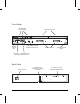
Front Panel hub status LEDs and reset button twisted-pair port LEDs Optional AUI port module installed in AUI/Xcvr slot ThinLAN network port twisted-pair ports cable management guide chain ports RS-232 console port (for distributed management) Back Panel power connector vi redundant power connector for the Hub-24 and Hub-48 cover plate over slot for HP Ethernet SNMP Module
Perforate HP Customer Support Services How to get the latest software/agent firmware You can download any of the following: HP AdvanceStack SNMP firmware: HP Interconnect Manager: HP Stack Manager asfw.exe icmupdt.exe stkmgr.exe from the HP BBS, HP FTP Library Service, CompuServe, and the World Wide Web. After you download the file, exact the file by typing filename /x. For example asfw.exe /x HP BBS Set your modem to N-8-1, set speed up to 14400 bps, and with your telecommunication program (e.g.
Contents 1 Installing the HP AdvanceStack 10Base-T Hubs Installation Summary . . . . . . . . . . . . . . . . . . . . . . . . . . . 1-2 Included Parts . . . . . . . . . . . . . . . . . . . . . . . . . . . 1-2 Installation Steps . . . . . . . . . . . . . . . . . . . . . . . . . . . . . 1-3 1. Install Add-in Modules (optional) . . . . . . . . . . . . . . . . . 1-3 2. Verify the Hub’s Operation . . . . . . . . . . . . . . . . . . . . . 1-4 3. Mount the Hub . . . . . . . . . . . . . . . . . . . . . . . . . . .
Contents 2 Installing and Using HP Stack Manager Software Description . . . . . . . . . . . . . . . . . . . . . . . . . . . 2-2 Computer Requirements . . . . . . . . . . . . . . . . . . . . . . . . . 2-3 Installing and Starting HP Stack Manager . . . . . . . . . . . . . . . 2-4 HP Stack Manager Basic Features . . Communications Settings . . . . Connect/Disconnect . . . . . . . Automatic Chain Display . . . . Online Help . . . . . . . . . . . . Port Status Display . . . . . . . . LAN Traffic Statistics . .
Contents 3 Hub Reference Front and Back Panel Descriptions . . . . . . . . . . . . . . . . . . . 3-2 Front of the hub . . . . . . . . . . . . . . . . . . . . . . . . . . 3-3 Back of the Hub . . . . . . . . . . . . . . . . . . . . . . . . . . . 3-5 How the Hubs Work . . Collision Detection Auto-Segmentation Link Beat . . . . . . . . . . . . . . . . . . . . . . . . . . . . . . . . . . . . . . . . . . . . . . . . . . . . . . . . . . . . . . . . . . . . . . . . . . . . . . . . . . . . . .
Contents 4 Troubleshooting Troubleshooting Approaches . . . . . . . . . . . . . . . . . . . . . . 4-2 Diagnosing with the LEDs . . . . . . . . . . . . . . . . . . . . . . . . 4-3 LED Pattern During Self-Test . . . . . . . . . . . . . . . . . . . 4-3 LED Error Indications . . . . . . . . . . . . . . . . . . . . . . . 4-4 Installation Problems . . . . . . . . . . . . . . . . . . . . . . . . . . . 4-6 Incorrect Installation . . . . . . . . . . . . . . . . . . . . . . . .
Contents A Cables and Connectors Recommended Cables . . . . . . . . . . . . . . . . . . . . . . . . . . A-3 Twisted-Pair Cable/Connector Pin-Outs . . . . . . . . . . . . . . . . Twisted-Pair Cable for Hub-to-Computer Network Connection Twisted-Pair Cable for Hub-to-Hub Distributed Management Chaining (not a network connection) . . . . . . . . . . . . . . Twisted-Pair “Crossover” Cable for Hub-to-Hub Network Connection . . . . . . . . . . . . . . . . . . . . . . . . . . . . .
Contents D Backup Links Description . . . . . . . . . . . . . . . . . . . . . . . . . . . . . . . . D-2 Limitations . . . . . . . . . . . . . . . . . . . . . . . . . . . . . D-3 Additional Notes . . . . . . . . . . . . . . . . . . . . . . . . . . D-3 Configuring a Backup Link . . . . . . . . . . . . . . . . . . . . . . . . D-4 Identifying the Backup Link . . . . . . . . . . . . . . . . . . . . . . . D-5 Indications of Backup Link Activation . . . . . . . . . . . . . . . . . . . . . . . . . . . . . . . . .
1 Installation Summary Installation Steps 1. Install Add-in Modules (optional) 2. Verify the Hub’s Operation 3. Mount the Hub 4. Complete the Network Connections to the Hub 5.
Installing the HP AdvanceStack Hubs Installing the HP AdvanceStack 10Base-T Hubs Installation Summary The basic hardware installation procedure for the HP AdvanceStack 10Base-T Hubs is as follows: 1. Install the Ethernet SNMP Module and/or one of the Transceiver Modules (optional). 2. Verify the hub’s operation. 3. Mount the hub in a rack, on a wall, or on a tabletop. 4. Connect the hub to a network or other hubs, and connect computer(s) and/or other device(s) to the hub’s ports. 5.
Installing the HP AdvanceStack 10Base-T Hubs Installing the HP AdvanceStack Hubs Power cord, one of the following: Australia/New Zealand (8120-6175) Denmark (8120-6178) Europe (8120-6174) Switzerland (8120-6179) Japan (8120-6176) United Kingdom (8120-6173) United States/Canada (8120-6177) Installation Steps 1. Install Add-in Modules (optional) The HP AdvanceStack 10Base-T Hubs can be custom-configured by installing an optional Ethernet SNMP Module and/or an HP Transceiver Module.
Installing the HP AdvanceStack 10Base-T Hubs Installing the HP AdvanceStack Hubs 2. Verify the Hub’s Operation 1. Plug the power cord into the hub’s power cord receptacle and into an ac power source. power receptacle on the back of the Hub-24. Caution If your installation requires a different power cord than the one supplied with the hub, be sure to use a power cord displaying the mark of the safety agency that defines the regulations for power cords in your country.
Installing the HP AdvanceStack 10Base-T Hubs Installing the HP AdvanceStack Hubs 3. Mount the Hub The HP AdvanceStack hubs can be mounted in three ways: in a rack or cabinet on a wall on a table The hardware for mounting the hub is included in the Accessory Kit (5063-4251) packed with the hub. If you are mounting the hub to a wall, however, you will also need four 5/8-inch number 12 wood screws, which are not included in the Accessory Kit.
Installing the HP AdvanceStack 10Base-T Hubs Installing the HP AdvanceStack Hubs Mounting the Hub in a Rack or Cabinet Note that the rack or cabinet should be adequately secured to prevent it from falling over. 1. Using a Phillips (cross-head) screwdriver, attach the mounting brackets to the hub with the 10-mm M4 screws included in the Accessory Kit. The top of each bracket should align with the top of the hub. align top of bracket with top of hub Be careful not to overtighten the screws.
Installing the HP AdvanceStack 10Base-T Hubs Installing the HP AdvanceStack Hubs Important Note Steps 2 through 4 below apply to mounting a single hub or the first of multiple hubs in a rack. The mounting brackets are designed to make it easy to install this first hub, and once it is installed correctly, to easily install subsequent hubs by placing them on top, one at a time, and then securing them to the rack. To make the process easy, it is important to get the first hub located correctly.
Installing the HP AdvanceStack 10Base-T Hubs Installing the HP AdvanceStack Hubs 3. Place the hub in the rack and lower it so the notches in the bottom of the bracket slide onto the two screws. Tighten these screws—be careful not to overtighten. Upper hole in the bracket Lower notch in the bracket 4. Install the other two number 12-24 screws into the upper hole in each bracket. Be careful not to overtighten these screws. Install additional screw Continued on the next page.
Installing the HP AdvanceStack 10Base-T Hubs Installing the HP AdvanceStack Hubs Notice that for the first hub you mounted, you used the bottom notch and the top hole in the bracket. For the next hub above, you use the bottom hole and the top notch, as show in the illustration below. Continue to alternate “notch and hole, hole and notch” for all hubs to be installed. To assist you, a single hash mark is located by one notch/hole pair and a double hash mark is located by the other pair on the bracket.
Installing the HP AdvanceStack Hubs Installing the HP AdvanceStack 10Base-T Hubs Mounting the Hub on a Wall Important A hub should be mounted only to a wall or wood surface that is at least 1/2-inch plywood or its equivalent. 1. Using a Phillips (cross-head) screwdriver, attach the mounting brackets to the hub in one of the positions shown in the illustrations below with the 10-mm M4 screws included in the Accessory Kit. 2.
Installing the HP AdvanceStack 10Base-T Hubs Installing the HP AdvanceStack Hubs 4. Complete the Network Connections to the Hub Reconnect the hub to the power source and then make the network connections to the hub. (For the Hub-24 and Hub-48, see the documentation accompanying the Redundant Power Supply if you are using redundant power.
Installing the HP AdvanceStack 10Base-T Hubs Installing the HP AdvanceStack Hubs Hub-to-Hub Network Connections The HP AdvanceStack 10Base-T Hubs can be connected together using any of the hub’s network ports. It is strongly recommended that you use the built-in ThinLAN (BNC) port for connecting hubs together.
Installing the HP AdvanceStack 10Base-T Hubs Installing the HP AdvanceStack Hubs Hub-to-Network Backbone Connections A single HP AdvanceStack 10Base-T Hub or a stack of hubs can be connected to a network backbone. These examples show connection to ThinLAN and fiber-optic backbones.
Installing the HP AdvanceStack 10Base-T Hubs Installing the HP AdvanceStack Hubs Network Port Connections The HP AdvanceStack 10Base-T Hubs have the following network ports: twisted-pair ThinLAN (BNC) AUI/Xcvr Slot This section describes how to connect cables to these ports. Twisted-pair Connections Twisted-pair connections can be made through the 12-port hub’s built-in RJ-45 jacks and the 24 and 48-port hubs’ 50-pin telco connectors, used either directly or with a 50-pin/RJ-45 Adapter (J2605-61001).
Installing the HP AdvanceStack 10Base-T Hubs B 12 11 10 9 8 7 6 5 4 3 2 12 10 8 6 4 2 11 9 7 5 3 1 1 B Installing the HP AdvanceStack Hubs Using RJ-45 Connectors: Push the RJ-45 plug into the RJ-45 jack until the tab on the plug clicks into place. 10Base-T Hub-24 RJ-45 plug unshielded twisted-pair cable To disconnect an RJ-45 plug, press the small tab on the plug and, holding it up, pull the plug out of the jack.
Installing the HP AdvanceStack 10Base-T Hubs Installing the HP AdvanceStack Hubs 2. Insert the hook into the slot on the hub’s face. insert hook in slot press telco plug onto connector secure plug with attached screw 3. Pivot the telco plug onto the 50-pin telco connector and press it into place. 4. Make sure the mounting hook is in the hub’s slot, then secure the telco plug to the hub by tightening the screw on the telco plug into the hole on the hub. Be careful not to overtighten the screw.
Installing the HP AdvanceStack 10Base-T Hubs Installing the HP AdvanceStack Hubs ThinLAN Connections To connect a ThinLAN cable to the hub’s ThinLAN port: 1. Attach a ThinLAN cable section to one side of a BNC “T” connector. (Hewlett-Packard offers BNC “T” connectors with insulating covers. Order product number HP 92227A.) 2. Attach another ThinLAN cable section or a 50-ohm terminator to the other side of the “T” connector. 3. Attach the “T” connector to the ThinLAN port.
Installing the HP AdvanceStack 10Base-T Hubs Installing the HP AdvanceStack Hubs AUI/Xcvr Slot Optional transceiver modules can be installed in the hubs’ AUI/Xcvr slot to provide additional connectivity choices, including: HP Fiber-Optic Transceiver Module (HP J2606A)—for 10Base-FL HP Twisted-Pair Transceiver Module (HP J2607A)—for 10Base-T HP ThinLAN Transceiver Module (HP J2608A)—for 10Base2 HP AUI Port Module (HP J2609A)—to attach external transceivers See the documentation accompanying the optional tr
Installing the HP AdvanceStack 10Base-T Hubs Installing the HP AdvanceStack Hubs Cable Management The HP AdvanceStack hubs have been designed to help you with the problem of managing your network cables. On the right side of each hub is a built-in cable management bar. cable management bars The bars have slots in them that you can use for tie-wrapping the network cables.
Installing the HP AdvanceStack 10Base-T Hubs Installing the HP AdvanceStack Hubs 5.
Installing the HP AdvanceStack 10Base-T Hubs Installing the HP AdvanceStack Hubs Using a Direct Serial Connection The out-of-band management port on the hub is a 9-pin serial (RS-232-C) port used to connect the hub to the personal computer or terminal. Note that you must have an HP Ethernet SNMP Module installed in the hub to use the ASCII console. To connect to the PC or terminal through the out-of-band management port: 1.
Installing the HP AdvanceStack 10Base-T Hubs Installing the HP AdvanceStack Hubs 3. For a hub with an SNMP module and the RS-232 cable connected to a terminal, switch on the terminal’s power (or switch on the PC’s power and start the terminal emulation program). Configure the terminal for 8 bits per character, 1 stop bit, no parity, Xon/Xoff handshaking, and a baud rate of 38400, 19200, 9600, 4800, 2400, or 1200. 4. For a terminal, press return several times for the prompt, =>.
Installing the HP AdvanceStack 10Base-T Hubs Installing the HP AdvanceStack Hubs 3. Connect the “local modem” to the serial port on your PC or install it in the PC if it is an internal modem, and configure that modem by using the “Local Modem” initialization screen in HP Stack Manager. 4. From the “Communications” screen under the “Settings” menu, click on the Modem button and enter the phone number of the remote modem. 5.
Installing the HP AdvanceStack 10Base-T Hubs Installing the HP AdvanceStack Hubs Using the Distributed Management Chain It is not necessary for each hub in a chain to be connected to the computer that is running HP Stack Manager or an ASCII terminal. When you have “chained” several hubs together through their Extension ports, only one of the chained hubs needs to have a connection to the computer.
2 Software Description Computer Requirements Installing and Starting HP Stack Manager HP Stack Manager Basic Features HP Stack Manager Advanced Features Installing and Using HP Stack Manager
Installing and Using HP Stack Manager This chapter describes how to install and use the HP Stack Manager software and lists the program’s basic and extended features. The HP AdvanceStack hubs can be controlled from an ASCII terminal or terminal emulation program but this requires that the hub (or one of the hubs in the stack) have an HP Ethernet SNMP Module installed. See the HP Ethernet SNMP Module manual for more information on using the ASCII console.
Installing and Using HP Stack Manager Computer Requirements The HP Stack Manager software runs on IBM-compatible personal computers with the following minimum configuration: Installing and Using HP Stack Manager Microsoft Windows version 3.1 (or later) 80386 (or higher) processor 4 Mbytes of RAM 2 Mbytes of available hard disk space a 3-1/2" 1.
Installing and Using HP Stack Manager Installing and Starting HP Stack Manager To install the HP Stack Manager software: 1. With Windows running, insert the floppy diskette into your computer’s diskette drive. Installing and Using HP Stack Manager 2. Select the Run option from the Program Manager File menu. 3. Type the following into the command line entry field: [drive] :\setup where [drive] is the letter designating your diskette drive. For example, “b:\setup”.
Installing and Using HP Stack Manager Using Windows The HP Stack Manager software uses the standard features of the Microsoft Windows user interface. If you are unfamiliar with using Windows, consult your Windows documentation for more details on using a mouse, menus, icons, buttons, online help, and other Windows features. Using Online Help Installing and Using HP Stack Manager Specific information about the HP Stack Manager software is included in the online help that accompanies the software.
Installing and Using HP Stack Manager Port enable/disable Reset Redundant Power Supply (RPS) status (for the Hub-24 and Hub-48) There is also an extended set of features available only to hubs that have an HP J2603A or B Ethernet SNMP Module installed. These are described later in this chapter under “Advanced Features”. Features not available to your hub will be “grayed out” on the HP Stack Manager menus and/or any associated buttons will not be displayed.
Installing and Using HP Stack Manager Automatic Chain Display The Chain Display window displays a list of HP AdvanceStack hubs that HP Stack Manager detects in the chain to which you have connected. Information about each hub is shown including the hub model and its station address. From this window you can access any of the hubs in the chain and, if you so desire, monitor it and/or change its configuration.
Installing and Using HP Stack Manager Port Enable/Disable This function turns the port selected on the Port Status display on or off. Port Counters Installing and Using HP Stack Manager The Port Counters function displays summary tables of several counters that are useful in diagnosing problem conditions on the hub’s ports. Counter values are displayed for each of the hub’s network ports. See the HP Stack Manager online help for counter descriptions.
Installing and Using HP Stack Manager HP Stack Manager Advanced Features In addition to the basic features described earlier in this chapter, the following HP Stack Manager advanced features are available on hubs that have an HP J2603A or B Ethernet SNMP Module installed: Higher-speed serial access Modem access for HP Stack Manager Installing and Using HP Stack Manager IP configuration Password Authorized managers Backup link Robust Capabilities Network test Factory default reset A description of each ext
Installing and Using HP Stack Manager IP Configuration The IP Configuration window is used to define the parameters necessary for the hub to communicate with a network management station using the TCP/IP network protocol. The hub’s default configuration causes the hub to retrieve this information automatically from an IP server using the Bootstrap Protocol (BOOTP).
Installing and Using HP Stack Manager Authorized Managers The Authorized Managers window is used to specify the IP or IPX network addresses of SNMP management stations authorized to manage this hub and which of the stations should receive SNMP event alarms. Backup Link Installing and Using HP Stack Manager The Backup Link window is used to specify two of the hub’s network ports (AUI, ThinLAN, or twisted-pair) to be used in a backup (redundant) connection to another hub.
Installing and Using HP Stack Manager Network Tests The Network Tests window enables you to perform Ping, IPX, and Link network tests. These tests are used to verify the connection between the hub and a specified network device. The devices tested must support the test(s) by being able to send the appropriate response packets. HP AdvanceStack 10Base-T hubs support all of these tests.
3 Front and Back Panel Descriptions How the Hubs Work Managing Your Hub — HP Distributed Management Optional Accessories Firmware Enhancements Hub Reference
Hub Reference Front and Back Panel Descriptions Front Panel The 24-port hub is shown; the 12-port and 48-port hubs are essentially the same.
Hub Reference Front of the hub Status LEDs The Status LEDs indicate whether the hub is functioning properly or not. For further details on error conditions indicated by the Status LEDs, see chapter 4, “Troubleshooting”. LED Power (green) ExpSlot (green) State Meaning On The hub is receiving power. Off The hub is not receiving power. On An optional HP SNMP Module is properly installed in the hub’s back panel slot. Off An SNMP Module is not installed.
Hub Reference Port LEDs (green) There is an LED associated with each network port on the hub, twisted-pair, the AUI/Xcvr port, and the ThinLAN port. Each port LED indicates the status of the port associated with it. Port Type LED State Twisted-pair On Link beat is detected from the attached node. Off The port is not receiving the link beat signal from the attached node. Flashing Slowly * Meaning The port has been auto-segmented. The Fault LED will also be flashing at the same rate.
Hub Reference Back of the Hub Expansion Slot The Expansion Slot is used to add an HP Ethernet SNMP Module (HP J2603A or B). See the “Optional Accessories” section later in this chapter for more information on the HP Ethernet SNMP Module. Redundant Power Supply Connector The back of the Hub-24 and Hub-48 has a Redundant Power Supply (RPS) connector to add the HP J2962A Redundant Power Supply.
Hub Reference Auto-Segmentation The Basic Feature The hub will automatically segment (temporarily disable) a network port if a collision condition exists for an excessive duration (between 1024 and 2048 bit times) or occurs during each of 32 consecutive attempts to transmit. The hub monitors the segmented port and automatically re-enables the port when a minimum length packet can be successfully transmitted or received without a collision occurring. Excessive collisions may be caused by faulty wiring.
Hub Reference Late collisions occur when a node starts transmitting after another node has already transmitted at least 512 bits. They are usually caused when network topology rules (such as cable length limitations or hub hop counts) do not meet the IEEE 802.3 specifications. Late collisions may also be caused by faulty wiring that prevents a hub from being able to detect traffic on a network port.
Hub Reference Managing Your Hub — HP Distributed Management One of the key features of the HP AdvanceStack family of hubs is the ease with which a hub can be managed. There are two main management options: Out-of-band management from a PC running HP Stack Manager connected to the RS-232 console port of any of the hubs in the stack. In-band management from a network management station running HP Interconnect Manager anywhere on the network that the hubs are in.
Hub Reference Chaining the Hubs The HP AdvanceStack hubs can be easily connected together with standard unshielded twisted-pair cable through their Extension (In/Out) ports to form a distributed management chain.
Hub Reference MIB (Management Information Base) Support The HP AdvanceStack 10Base-T Hub with an installed HP Ethernet SNMP Module supports the following MIB standards: MIB-II (RFC 1213), IEEE 802.3 Repeater MIB (RFC 1516), and IEEE 802.3 MAU MIB (RFC 1515). In addition, the hub implements HP MIB extensions that are available on request. Contact your HP-authorized LAN dealer or local HP sales office.
Hub Reference Port Security Note This feature is configurable over the network from a network management station running HP Interconnect Manager, or out-of-band from an ASCII terminal or terminal emulator. The HP AdvanceStack 10Base-T Hub with HP Ethernet SNMP Module provides two main types of security on each of its network ports.
Hub Reference Password Protection The hub can be assigned a password to restrict access to the hub’s console interface and to the hub’s configuration from network management stations. The password also acts as the SNMP community name. The password is configured through the “Password” function in the HP Stack Manager program. See chapter 2, “Installing and Using HP Stack Manager”, for more information; see the HP Ethernet SNMP Module manual for the PAssword command.
Hub Reference Automatic sensing of the baud rate on the out-of-band management port, and support for higher port baud rates beyond the default 9600 baud. Full V.22bis modem line control for remote out-of-band management access to the hub or stack of hubs. Capability to manage up to 16 hubs in a chain, even if the other hubs do not have management modules. Security features including port security, network management authorization, and hub access password protection.
Hub Reference HP Transceiver Modules The HP Transceiver Modules are optional modules that can be added to an HP AdvanceStack hub. They provide extended connectivity choices from the hub to Ethernet networks.
Hub Reference HP Router Module The HP J2628A Router 210 Module is an auxiliary module for the HP AdvanceStack 10Base-T Hub. The Router 210 Module attaches to the HP J2603B Ethernet SNMP Module and is then installed in the hub’s expansion slot.
Hub Reference AppleTalk Phase 2 Transparent bridging with support for the Spanning Tree Protocol The router module can be configured and managed in various ways: Through the hub’s RS-232 Distributed Management port, connected (locally, or through a modem) to a PC running the HP Stack Manager software supplied with the router module (HP Stack Manager runs the router module’s VT-100 terminal interface) Through any standard SNMP network management software, such as HP Interconnect Manager in HP-UX Through Tel
Hub Reference HP Dial-a-LAN Remote Access Server The two HP AdvanceStack Dial-A-LAN auxiliary modules are remote access servers for Ethernet networks. These products serve remote PCs, Macintoshes, and UNIX workstations by allowing users to dial in to a 12, 24, or 48-port AdvanceStack hub. The two models are: a two-port version: HP J2623A AdvanceStack Dial-A-LAN 2A/Plus V.
Hub Reference HP J2624A Dial-A-LAN 4A If you need more than two ports, the HP Dial-A-LAN 4A has four RS-232 ports for connecting up to four external modems. This module can also be used in an ISDN environment. Both the 2-Port and 4-Port modules support these features: Access speeds available to 115 Kbps. Throughput speeds available are dependent on line quality, type of data transmitted, and the remote node’s ability to function at this sustained rate.
Hub Reference Firmware Enhancements Hewlett-Packard continually tests and improves its products. When firmware enhancements are made to the HP AdvanceStack hubs that have an optional HP Ethernet SNMP Module installed, you will be able to easily update them with the new code. The updated code can be loaded from a PC attached to the hub’s out-of-band management port or downloaded over the network. See the end of chapter 4, “Troubleshooting” for information on how to download the latest agent code.
4 Troubleshooting Approaches Diagnosing with the LEDs Installation Problems Cabling Problems Unusual Network Activity IP Configuration Errors Diagnostic Tests Customer Support Services Troubleshooting
Troubleshooting This chapter describes how to diagnose and resolve operating problems with the HP AdvanceStack 10Base-T Hubs. This chapter describes these topics: basic troubleshooting approaches diagnosing with the LEDs installation, cabling, and unusual network activity problems diagnostics tests Additionally, certain diagnostic functions useful for troubleshooting are contained in the HP Stack Manager software.
Troubleshooting Diagnosing with the LEDs Most problems with the hub can be diagnosed using the LEDs on its front panel. This section describes the normal LED pattern when the hub is being self-tested, and LED patterns that indicate error conditions on the hub. LED Pattern During Self-Test When the hub is first turned on and whenever it is reset, it performs a self-diagnostic test during which time all the LEDs should be lit.
Troubleshooting LED Error Indications The tables on the next two pages describe LED patterns that indicate error conditions. LED patterns indicating problems Power Collision Fault Security Diagnostic Tips RPS Exp Slot Port OFF * * * * * * ON * OFF OFF * * OFF or flashing intermittently for a port in use. Check power cord and power source. If OK, replace hub. Check cabling on indicated port. Use HP Stack Manager or the ASCII console STatus command to determine the state of the port.
Troubleshooting LED patterns indicating problems Power Collision Fault Security Diagnostic Tips RPS Exp Slot Port ON * Slow Flash OFF * * Slow Flash The port has been auto-segmented because of too many collisions. Check cable terminations, connections, SQE setting on any external transceivers, and status of attached network devices for causes of the excess collisions. ON * Slow Flash * Slow Flash * * The redundant power supply (RPS) may no longer be providing redundant power.
Troubleshooting Installation Problems By carefully following the installation procedures described in chapter 1, “Installing the HP AdvanceStack 10Base-T Hubs”, you can avoid most problems caused by improper installation of the hub or one of its components. Incorrect Installation Incorrectly installing the hub, the HP Ethernet SNMP Module, or a transceiver module can result in one or all of these components malfunctioning or not functioning at all.
Troubleshooting Cabling Problems A high percentage of network problems are due to faulty cabling. Cabling problems usually result in the failure of a hub to connect to a network, another hub, or the console. Connections All cables attached to the hub should be checked to see that they are properly connected. Proper network and out-of-band management connections are described in chapter 1, “Installing the HP AdvanceStack 10Base-T Hubs”.
Troubleshooting Topology It is important to make sure you have a valid network topology. Common topology faults include excessive cable length and excessive repeater delays between nodes. If you have trouble after recent changes to a network, switch back to the previous topology. If you no longer have any trouble, the new topology is probably at fault. Refer to the guide entitled Designing HP AdvanceStack Workgroup Networks for topology configuration guidelines.
Troubleshooting Diagnostic Tests The HP Stack Manager software provides tests and indicators that can be used to monitor the hub and its network connections. See chapter 2, “Installing and Using HP Stack Manager”, and the software’s online Help system for more details about these tests and indicators. Testing the Hub Only If you believe that the hub is not operating correctly, you can test the hub’s circuitry by resetting the hub through one of these procedures: Press the Reset button.
Troubleshooting Select Ping Test from HP Stack Manager’s Network Test function or type the PIng command at the ASCII terminal. This is a network layer test that you can run on TCP/IP networks. The hub sends IP Echo Request packets to a specified network device. This works with devices that have an IP address and are able to respond to an ICMP Echo Request packet. You specify the remote device by its IP address. Select IPX Test from HP Stack Manager’s Network Test function.
Troubleshooting Clearing a Password There is a Password Clear button on the HP Ethernet SNMP Module that is accessed through a hole in the hub’s Expansion Slot cover plate. You can use this button to clear a forgotten password that was previously configured on the hub. The password is configured from either: HP Stack Manager HP Interconnect Manager, or ASCII terminal interface Press the Password Clear button with a pen or other pointed object.
Troubleshooting Customer Support Services Hewlett-Packard offers support 24 hours a day, seven days a week through the use of automated electronic services including: Hewlett-Packard BBS and World Wide Web Hewlett-Packard FTP Library Service on the Internet CompuServe HP FIRST FAX Retrieval Service HP Interconnect Manager (icmupdt.exe), HP Stack Manager (stkmgr.exe) and SNMP firmware for your AdvanceStack hubs (asfw.
Troubleshooting Hewlett-Packard FTP Library Service To access the HP FTP Library, follow these steps: 1. Enter the command: ftp ftp-boi.external.hp.com The ftp> prompt appears. 2. At the ftp > prompt, enter: anonymous 3. At the password prompt, enter your internet e-mail address. 4. At the ftp > prompt, set the transfer type to binary: bin 5. Change directories: cd pub/networking/software 6. Retrieve the file by entering: get filename (e.g., get asfw.exe) 7. Quit the FTP session by entering: quit 8.
Troubleshooting CompuServe CompuServe is an electronic information and communication service run by an independent company. The service is typically accessed with a computer and modem and uses standard voice telephone lines for transmitting and receiving data. CompuServe is available 24 hours-a-day, seven days per week. The participants pay a monthly fee as well as an hourly connect charge for this service. To get the latest agent firmware from CompuServe, follow these steps: 1. Login to CompuServe. 2.
Troubleshooting HP FIRST Fax Retrieval Service HP FIRST is an automated fax retrieval service that is available 24 hours a day, seven days a week. HP FIRST provides information on the following topics: Product information Troubleshooting instructions Technical reviews and articles Configuration information To access HP FIRST, dial one of the following phone numbers from your touch-tone telephone: Location Phone Number U.S. and Canada Only (800) 333-1917 and press 1 for HP FIRST Outside the U.S.
A Recommended Cables Twisted-Pair Cable/Connector Pin-Outs ThinLAN Cable Requirements AUI Cable Minimum Pin-Out Distributed Management Connector/Cable Pin-Outs Cables and Connectors
Cables and Connectors Cables and Connectors This appendix lists cables that have been tested and verified for use with the HP AdvanceStack 10Base-T Hubs. It also includes minimum pin-out information so, if you wish to use an unlisted cable, you can verify that the cables used in your installation are correctly wired. Note that each pin-out does not necessarily match the pin-out for the corresponding HP cable, but cables manufactured to follow the minimum pin-out will function correctly.
Cables and Connectors Cables and Connectors Recommended Cables Cable Function Port Type on PC, or Modem Cable Type HP Product Number Network connections to the hub: Hub to end node connection — Twisted-pair “straight- 92268A, B, C, D, or N (4-pair) through” cable 92214R, S, or T (25-pair) Hub to hub “cascade” connection — Twisted-pair “crossover” cable 92214W (6-inch Crossover Cable) Hub to hub ThinLAN backbone connection — IEEE Type 10Base2 Thin coaxial cable 92214U (0.
Cables and Connectors Cables and Connectors Twisted-Pair Cable/Connector Pin-Outs Twisted-Pair Cable for Hub-to-Computer Network Connection To connect PCs or other network devices to the hub, use a “straight-through” 10Base-T cable. The twisted-pair wires must be twisted through the entire length of the cable. The wiring sequence must conform to AT&T 258A (not USOC ). See “Twisted-Pair Cable Pin Assignments” later in this chapter for a listing of the signals used on each pin.
Cables and Connectors Cables and Connectors Twisted-Pair Cable for Hub-to-Hub Distributed Management Chaining (not a network connection) To connect hubs to each other through the Extension (In/Out) Ports to form a distributed management chain, use a “straight-through” 10Base-T cable. The twisted-pair wires must be twisted through the entire length of the cable. The wiring sequence must conform to AT&T 258A (not USOC).
Cables and Connectors Cables and Connectors Twisted-Pair “Crossover” Cable for Hub-to-Hub Network Connection For wiring between two hubs for data communications, the transmit and receive pairs must be reversed. The twisted-pair wires must be twisted through the entire length of the cable. See “Twisted-Pair Cable Pin Assignments” later in this chapter for a listing of the signals used on each pin.
Cables and Connectors Cables and Connectors Twisted-Pair Cable Pin Assignments Twisted-Pair Straight-Through Cable Hub End Signal (receive +) (receive –) (transmit +) (transmit –) Computer or Transceiver End Pins Pins 1 2 3 6 1 2 3 6 Signal (transmit +) (transmit –) (receive +) (receive –) Twisted-Pair Crossover Cable Hub 1-end Signal (receive +) (receive –) (transmit +) (transmit –) Hub 2-end Pins Pins 1 2 3 6 6 3 2 1 Signal (transmit –) (transmit +) (receive –) (receive +) ThinLAN Cable Req
Cables and Connectors Cables and Connectors AUI Cable Minimum Pin-Out Transceiver end 15-pin female Hub end 15-pin male 2 3 4 5 6 9 10 12 13 2 3 4 5 6 9 10 12 13 Signal Control In circuit A Data Out circuit A Data In circuit Shield (common drain) Data In circuit A Voltage Common Control In circuit B Data Out circuit B Data In circuit B Voltage Plus For this connection, you can use: HP 92264D (1-meter thin AUI extension, pin 4 not connected) HP 92254A through H (6-meter through 48-meter thick AUI cab
Cables and Connectors Cables and Connectors Distributed Management RS-232 Connector and Cable Pin-Outs The hub’s console connector is wired as if it is a terminal (DTE), ready to be connected to a modem (DCE). The HP AdvanceStack 10Base-T Hubs include a null modem cable that can be used to directly connect a PC to be used as the console. To connect a modem to the hub, use a standard RS-232-C modem cable.
Cables and Connectors Cables and Connectors RS-232-C “Null Modem” Cable for Direct Console Connection (supplied with the hub) PC end 9-pin female Hub end 9-pin female 2 2 Rx 3 3 Tx 5 5 GND RS-232-C Modem Cable Modem end 25-pin male Hub end 9-pin female 2 3 Tx 3 2 Rx 4 7 RTS 5 8 CTS 6 6 DSR 7 5 GND 8 1 CD OR DCD 20 4 DTR 22 9 RI 23 A-10 Signal DRS – typically on V.
B Specifications
Specifications Physical HP J2600A 12-Port Hub HP J2601B 24-Port Hub HP J2602B 48-Port Hub Width: 44.2 cm (17.4 in) 44.2 cm (17.4 in) Depth: 29.8 cm (11.7 in) 29.8 cm (11.7 in) Height: 6.6 cm (2.6 in) 11.0 cm (4.3 in) Weight: 4.1 kg (9.0 lb) 5.0 kg (11.0 lb) Electrical Specifications (The HP AdvanceStack hubs automatically adjust to any voltage between 100 and 240 volts and any frequency between 50 and 60 Hz.
Specifications Electromagnetic Emissions FCC part 15 Class A CISPR-22 Class A EN 55022 Class A VCCI Level I Immunity ESD IEC 801-2 (1991) (4 kV CD, 8 kV AD) Radiated (Immunity) IEC 801-3 (1984) (3 V/m) Electrical Fast Transient IEC 801-4 (1988) 0.5kV signal lines 1.0kV power lines Specifications Safety IEC 950: (1991)+A1,A2/.
C Communications Between Hub and Network Management Station IPX Addressing for Novell NetWare IP Addressing for IP and non-IP Networks Using BOOTP Network Addressing
Network Addressing Communication Between the Hub and Network Management Station The HP AdvanceStack 10Base-T Hubs that have an HP Ethernet SNMP Module (HP J2603A or B) installed in them can be managed over the network by HP network management products, for example HP Interconnect Manager. These hubs can also be managed by any other network management products that comply with the Simple Network Management Protocol (SNMP) standard and have standard SNMP MIB-browser functionality.
Network Addressing IPX Addressing for Novell NetWare The Novell NetWare network operating system uses a proprietary protocol called Internetwork Packet Exchange (IPX). The IPX protocol firmware is always available on an HP AdvanceStack 10Base-T Hub; it becomes active when the hub gets an IPX address. The IPX address consists of a network number and a device identification.
Network Addressing IP Addresses for IP and Non-IP Networks If you have chosen to manage your hub with an SNMP/IP network manager, your hub must be configured with an IP address. If your network will be connected with other networks that use IP addresses, you must use assigned IP addresses. Otherwise, you can build your own IP addressing scheme (described on the next page).
Network Addressing The following documents have detailed descriptions on how to build your own IP addressing scheme: HP Interconnect Manager Getting Started Guide: (OpenView/Windows: HP part number 5963-2619) (OpenView/HP-UX: HP part number 5963-2687) Internetworking With TCP/IP: Principles, Protocols, and Architecture Author: Douglas E. Comer Publisher: Prentice-Hall, Inc. Example Addressing Scheme On the next page is an example of a class C addressing scheme.
Network Addressing Using BOOTP BOOTP (Bootstrap Protocol) is used to download network configuration data from a server (the BOOTP server) to the hub. The configuration data the hub retrieves from the BOOTP server is: the IP address for the hub the subnet mask for the subnet on which the hub is installed the default router If you have configured the hub’s IP parameters on a BOOTP server, you do not need to use the IP Configuration function in HP Stack Manager.
Network Addressing Definitions of the table entry fields: hphub24 is a user-defined symbolic name to help you find the correct section of the bootptab file. If you have multiple hubs that will be using BOOTP to get their IP configuration, you should use a unique symbolic name for each hub. ht is the “hardware type” tag. For the HP AdvanceStack 10Base-T hubs, set this to ether (for Ethernet). This tag must precede the ha tag. ha is the “hardware address” tag. Use the hub’s 12-digit station address.
D Description Configuring a Backup Link Identifying the Backup Link Indications of Backup Link Activation Reactivating the Primary Link Example Topologies Backup Links
Backup Links Description Note The Backup Link function is available only for HP AdvanceStack 10Base-T Hubs in which an HP Ethernet SNMP Module (HP J2603A or B) is installed. In some network configurations a critical link exists, for example between two workgroups that regularly share or exchange data over the network. To maintain the integrity of such a critical link, the HP AdvanceStack 10Base-T Hubs offer a backup link feature.
Backup Links Limitations The hubs at both ends of the redundant link must have an HP Ethernet SNMP Module installed. Each hub can monitor a single backup link (only one backup link can be configured on each hub). But, the hub may be at the remote end of one backup link and at the monitoring end of a backup link to a different hub. A given hub should be connected to the remote end of no more than two backup links.
Backup Links Configuring a Backup Link Configure the Monitoring Hub Only. All configuration of the backup link is performed from the HP Stack Manager program, and you perform the complete backup link configuration on the “monitoring” hub. On the “remote” hub, you only need to make sure the ports used in the primary and backup links are both enabled. Use the HP Stack Manager’s Backup Function. To configure this link, you use the Backup function in the HP Stack Manager.
Backup Links 4. Complete the network cable connections between the monitoring hub and the remote hub. (For instructions, see “Port Connections” in chapter 1, “Installing the HP AdvanceStack 10Base-T Hubs”.) 5. Enable the primary port with the HP Stack Manager’s Port function. This step is necessary because until you have completed step 3 (connecting the cables), the test packets cannot be successfully sent through the primary port.
Backup Links Indications of Backup Link Activation When the primary link fails (“n” consecutive test packet responses were not received on the primary port from the other hub), the backup link is automatically enabled. The effect of this change is displayed on the monitoring hub’s LEDs and management interface. Activation of the backup link does not change the status of any of the ports on the remote hub. On the hub’s LEDs, the primary port LED goes off, and the backup port LED goes on.
Backup Links Reactivating the Primary Link When the primary link is repaired, you can use any of the following methods to re-enable the primary port: From HP Stack Manager click on the primary port on the Port Status display and use the Port function to enable that port. From HP Stack Manager, use the Reset function to perform a Power-on reset. This will restore the primary port’s active status. From the ASCII terminal, use the POrt command to enable the primary port.
Backup Links Example Topologies Following are two simple example topologies that may give you some ideas on how a backup link could be used in your network. Example 1: Hub-to-Hub In this example topology, the primary and backup links consist of twisted-pair cable segments between two HP AdvanceStack hubs.
Backup Links Example 2: Backup Link Using Alternative Medium In this topology, the primary link consists of a twisted-pair cable between twisted-pair ports on two HP AdvanceStack hubs; the backup link is from AUI port to AUI port on the two hubs. Depending on the type of transceivers used, the backup link could use thin coax, fiber-optic cable, or even twisted-pair cable. Note that any of the network ports on these hubs can function as a backup to any other port.
Safety and Regulatory Statements
Safety and Regulatory Statements Safety Information Safety Symbols Documentation reference symbol. If the product is marked with this symbol, refer to the product documentation to get more information about the product. WARNING A WARNING in the manual denotes a hazard that can cause injury or death. CAUTION A CAUTION in the manual denotes a hazard that can damage equipment.
Symboles de sécurité Symbole de référence à la documentation. Si le produit est marqué de ce symbole, reportez-vous à la documentation du produit afin d’obtenir des informations plus détaillées. WARNING Dans la documentation, un WARNING indique un danger susceptible d’entraîner des dommages corporels ou la mort. CAUTION Un texte de mise en garde intitulé CAUTION indique un danger susceptible de causer des dommages à l’équipement.
Safety and Regulatory Statements Hinweise zur Sicherheit Sicherheitssymbole Symbol für Dokumentationsverweis. Wenn das Produkt mit diesem Symbol markiert ist, schlagen Sie bitte in der Produktdokumentation nach, um mehr Informationen über das Produkt zu erhalten. WARNING Eine WARNING in der Dokumentation symbolisiert eine Gefahr, die Verletzungen oder sogar Todesfälle verursachen kann. CAUTION CAUTION in der Dokumentation symbolisiert eine Gefahr, die das Gerät beschädigen kann.
Simboli di sicurezza Simbolo di riferimento alla documentazione. Se il prodotto è contrassegnato da questo simbolo, fare riferimento alla documentazione sul prodotto per ulteriori informazioni su di esso. WARNING La dicitura WARNING denota un pericolo che può causare lesioni o morte. CAUTION La dicitura CAUTION denota un pericolo che può danneggiare le attrezzature.
Safety and Regulatory Statements Consideraciones sobre seguridad Símbolos de seguridad Símbolo de referencia a la documentación. Si el producto va marcado con este símbolo, consultar la documentación del producto a fin de obtener mayor información sobre el producto. WARNING Una WARNING en la documentación señala un riesgo que podría resultar en lesiones o la muerte. CAUTION Una CAUTION en la documentación señala un riesgo que podría resultar en averías al equipo.
Safety and Regulatory Statements Safety Information Safety Information 7
Safety and Regulatory Statements Regulatory Statements FCC Statement (For U.S.A. Only) Federal Communications Commission Radio Frequency Interference Statement Warning: This equipment generates, uses, and can radiate radio frequency energy. If it is not installed and used in accordance with the instruction manual, it may cause interference to radio communications.
The following Declaration of Conformity for the HP AdvanceStack 10Base-T Hubs complies with ISO/IEC Guide 22 and EN 45014. The declaration identifies the product, the manufacturer’s name and address, and the applicable specifications that are recognized in the European community.
Index
Index Index Symbols C 50-pin telco connectors 1-15 50-pin/RJ-45 adapter 1-14 cable See also interface cable management 1-19 specialized cable tie 1-19 cable tie using 1-19 cables distributed management chain A-3 HP cables for console connection A-3 hub-to-hub cascading A-6 modem cable pin-out A-10 network connections A-3 RS-232 cable supplied with hub A-10 RS-232 console port A-3 twisted-pair connector pin-outs A-4 cables and connectors A-2 cabling problems 4-7 cascading hub to hub connection 1-12 twis
Index A-3 D Declaration of Conformity C-9 DECnet 3-15 default settings of the hub 2-12 descriptions front and back hub panels 3-2 HP Stack Manager 2-2 diagnosing with the LEDs 4-3 diagnostic tests 4-9 testing the hub only 4-9 testing the ports and links 4-9 testing twisted-pair cabling 4-10 distributed management 3-8 chain cables A-3 chain description 3-9 E electrical specifications B-2 electromagnetic specifications B-3 enabling/disabling network ports 2-8 enhancements, firmware 3-19 environmental speci
Index Index connect/disconnect function 2-6 factory reset option 2-12 higher serial access speeds 2-9 hub identification information 2-7 installation procedures 2-4 IP configuration function 2-10 LAN traffic statistics 2-7 modem access 2-9 network test function 2-12 online help 2-5, 2-7 part of distributed management 3-9 password function 2-10 port counters 2-8 port enable/disable 2-8 port status display 2-7 reset function 2-8 robust port control 2-11 RPS function 2-8 hub identification, in HP Stack Manag
Index N network addressing IP address C-4 IPX address C-3 network connections 50-pin telco connectors 1-15 50-pin/RJ-45 adapter 1-14 cable management 1-19 hub to computer connections 1-11 hub to hub connections 1-12 hub to network backbone 1-13 port connections 1-14 RJ-45 connectors 1-15 ThinLAN connector 1-17 network management communication with the hub C-2 description 3-9 HP management product 3-10 non-HP 3-10 network ports counter tables 2-8 enabling and disabling 2-8 network tests running from HP Stac
Index Index R rack or cabinet mounting 1-6 recommended cables A-3 Redundant Power Supply (RPS) from HP Stack Manager 2-8 on the back panel 3-5 Redundant Power Supply (RPS) LED Regulatory statements C-8 reset button 3-4 resetting the hub effect on HP Stack Manager 2-8 from HP Stack Manager 2-8 reset button 3-4 troubleshooting procedure 4-9 RJ-45 connectors 1-15 robust port control 2-11 router module about 3-15 RPS LED 3-3 RS-232 console port 1-iv 3-3 S Safety information C-2 security authorized managers
Index Index twisted-pair cable hub-to-computer connection A-4 hub-to-hub connection A-6 hub-to-hub management chain A-5 pin assignments A-7 pin-outs A-4 twisted-pair cabling testing 4-10 twisted-pair port LEDs 3-4 twisted-pair ports 1-iv 50-pin telco connectors 1-15 50-pin/RJ-45 adapter 1-14 connection procedures 1-14 RJ-45 connectors 1-15 U unusual network activity 4-8 V verifying hub operation 1-4 W wall mounting the hub 1-10 warranty summary statement B-3 World Wide Web obtaining software from 4-1
© Copyright 1995 Hewlett-Packard Company Printed in Singapore 10/95 Manual Part Number 5964-4601 *5964-4601*