H HP AdvanceStack Router 210 Module Installation Guide
Installation Guide HP AdvanceStack Router 210 Module
© Copyright Hewlett-Packard Company 1994. All rights reserved. This document contains proprietary information, which is protected by copyright. No part of this document may be photocopied, reproduced, or translated into another language without the prior written consent of Hewlett-Packard. Publication Number: 5963-2632, E1294 Edition 1, December 1994 Printed in U.S.A. Applicable Product HP J2628A Disclaimer The information contained in this document is subject to change without notice.
About This Manual This manual is both a task-oriented installation guide and a reference describing the hardware aspects of router features, operation, and troubleshooting. The manual is organized as follows: Chapter 1: Installation. Describes how to prepare the network, install the router module, connect the WAN cable, connect a console, and verify that the router module starts up properly. Chapter 2: Setup.
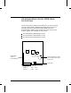
HP AdvanceStack Router 210 Module: An Overview The HP AdvanceStack J2628A Router 210 Module is an auxiliary module for the HP AdvanceStack J2603B Ethernet SNMP Module, which is an optional component of an HP AdvanceStack 10Base-T Hub.
The router module includes two ports: An external synchronous WAN port supporting RS-232/V.24/V.28, V.35, X.21, or RS-422/RS-449/V.36 interfaces at speeds of 9.6 Kbit/s to 2.048 Mbit/s. These allow HP Point-to-Point, PPP, V.25 bis (dial-up/ISDN), SMDS, frame relay, and LAPB (X.25) connections to other routers, over point-to-point or switched circuits. An internal Ethernet/802.3 LAN port, through which the router module communicates with the hub.
vi
Contents Contents Installation Installation Summary Contents 1. . . . . . . . . . . . . . . . . . . . . . . . . . . 1-2 Items Included With the Router Module . . . . . . . . . . . . . . . . 1-4 1. Check the Version of the SNMP Module. . . . . . . . . . . . . . . 1-5 Looking at the SNMP Module . . . . . . . . . . . . . . . . . . . . 1-5 Using HP Stack Manager . . . . . . . . . . . . . . . . . . . . . . . 1-7 2. Prepare the Network. . . . . . . . . . . . . . . . . . . . . . . . . . 1-8 3.
Contents 3. Operation LEDs and Buttons . . . . . . . . . . . . . . . . . . . . . . . . . . . . 3-2 Status LEDs . . . . . . . . . . . . . . . . . . . . . . . . . . . . . . 3-2 Reset and Clear Buttons . . . . . . . . . . . . . . . . . . . . . . . 3-4 Resetting and Clearing . . . . . Resetting the Router Module Clearing the Passwords . . . Clearing the Router Module . . . . . . . . . . . . . . . . . . . . . . . . . . . . . . . . . . . . . . . . . . . . . . . . . . . . . . . . . . . . . . . .
Contents C.
1 Installation Summary 1. Check the Version of the SNMP Module. 2. Prepare the Network. 3. Install the Router Module. 4. Connect the WAN Cable. 5. Connect a Console (Optional). 6. Verify That the Router Module Starts Up Properly.
Installation Installation Summary Installation Summary This chapter describes the installation procedures for the router module. The following is a summary of those procedures: 1. Check the Version of the SNMP Module. The HP AdvanceStack 10Base-T Hub in which the HP Router 210 Module is to be installed must also have an HP J2603B Ethernet SNMP Module installed. (The router module will be mounted on the SNMP module.) This SNMP module must be the HP J2603B version, not the HP J2603A version.
Installation Installation Summary f. Place the SNMP module, component-side down, on top of the router module, with the male connector on the SNMP module (behind the white extractor handle) mating with the female connector on the router module. g. Press the two connectors together, then insert and tighten the supplied screws through the holes in the SNMP module into the standoffs mounted on the router module. h.
Installation Items Included With the Router Module Items Included With the Router Module The following items are included with the router module: WAN Cable: The WAN cable you received with the router module depends on the option specified when the router module was ordered: Option Cable 001 V.35 (28606-63008) 002 RS-232/V.24/V.28 (28606-63006) 003 X.21 (28606-63001) 004 RS-449/RS-422/V.36 (28606-63005) For details about these cables, refer to appendix A, ‘‘Cables and Connectors’’.
Installation 1. Check the Version of the SNMP Module. 1. Check the Version of the SNMP Module. The HP AdvanceStack 10Base-T Hub in which the HP AdvanceStack Router 210 Module is to be installed must also have an HP J2603B Ethernet SNMP Module installed. (The router module will be mounted on the SNMP module.) This SNMP module must be the HP J2603B version, not the HP J2603A version.
Installation 1. Check the Version of the SNMP Module. 2. Look at the exposed edge of the SNMP module. • If an LED is mounted near the button switch, the installed SNMP module is the HP J2603B version; you can proceed with installing the router module. • If there is no LED there, the module is the HP J2603A version; contact your HP dealer for information about obtaining the HP J2603B version. Button switch If this LED is present, the SNMP module is the proper version Figure 1-2.
Installation 1. Check the Version of the SNMP Module. Using HP Stack Manager 1. Connect the serial port of a PC to the hub’s RS-232 Distributed Management port. (For details, refer to the hub’s installation guide.) 2. Start HP Stack Manager. (For information about installing and starting HP Stack Manager, refer to the hub’s installation guide. For specific information about using HP Stack Manager, refer to its online help.) 3. Click on the Connect button.
Installation 2. Prepare the Network. 2. Prepare the Network. 1. Create or update the network plan. Include all power sources, computers, data links, hubs, repeaters, bridges, other routers, and cabling (including types and lengths). Verify the design limits for the cable lengths and the number of repeaters and nodes in the network. 2. Create or update the network map. This map provides a diagram of how the network topology will look after the router module is installed.
Installation 2. Prepare the Network. 4. If the router is to be automatically configured after it is installed using a SmartBoot configuration created on another HP router or a Bootp server, make sure that the following has been done before you first boot the router (by powering on the hub): • The SmartBoot configuration has been created and assigned to the proper network port connected to the router module.
Installation 3. Install the Router Module. 3. Install the Router Module. The router module will be connected to the HP J2603B Ethernet SNMP Module, and then the assembled modules will be installed in the Expansion Slot in the back of the hub. Note The HP Ethernet SNMP Module must be the HP J2603B version, not the HP J2603A version.
Installation 3. Install the Router Module. To install the router module: 1. Using a Torx T-10 or flat-blade screwdriver, loosen the two captured screws holding the cover plate over the hub’s Expansion Slot, then remove the cover plate. Note that the screws are spring-loaded and will release outward when unscrewed far enough. Do not unscrew them completely from the cover plate. Loosen these two screws 1 Installation Figure 1-3. Cover Plate Screws 2.
Installation 3. Install the Router Module. 3. Holding the module by its edges—taking care not to touch the metal connectors—carefully remove the router module from its protective packaging. Place the module on a nonconducting antistatic surface. Note Save the original packaging material in case the router module needs to be returned to HP. The nonconducting antistatic material surrounding the router module ensures that the battery on the router module will not short out while being shipped. 4.
Installation 3. Install the Router Module. 6. Position the SNMP module, component-side down, above the router module as shown below. Before mating the modules, make sure that the four standoffs mounted on the router module are aligned with the inner of the two holes in each corner of the SNMP module. This is the hole closest to the center of the module, not the hole closest to the corner. 1 Installation Figure 1-6. Positioning SNMP Module Over Router Module 7.
Installation 3. Install the Router Module. 8. Insert the supplied 1⁄4-inch number 4-40 screws through the holes in the SNMP module into the standoffs, then secure them using a Phillips (cross-head) screwdriver. Do not overtighten the screws. Figure 1-8. Inserting Screws in Router Module Caution In the next step, be careful not to damage the router module by scraping it against the edges of the Expansion Slot. 9.
Installation 3. Install the Router Module. 10. Align the edges of the SNMP module in the small slots near the bottom of the Expansion Slot, then push the assembled modules fully into the slot—until you feel the connector on the SNMP module firmly engage its mating connector within the Expansion Slot. Caution For proper hub cooling, make sure you install the cover plate (as described in the next two steps) after the modules are installed. 11.
Installation 4. Connect the WAN Cable. 4. Connect the WAN Cable. Connect the WAN cable as described below. Also, if you have not already done so, verify that the network equipment and links (in particular, the WAN-link-terminating equipment) are operational. (Your WAN-link service provider can verify that the WAN link is operating correctly.) If the LAN links are not already connected to the hub, connect them now (refer to the hub’s installation guide). Caution Static discharge may damage equipment.
Installation 4. Connect the WAN Cable. The interface used for the WAN port—RS-232/V.24/V.28, V.35, X.21, or RS-422/RS-449/V.36—is determined automatically by the router, depending on which cable is attached to the port. The maximum length for an RS-232/V.24/V.28 cable connected to the WAN port is 15 meters (50 feet). 1 If an HP 28606-63006 5-meter RS-232/V.24/V.
Installation 5. Connect a Console (Optional). 5. Connect a Console (Optional). The router module can be verified to be operating correctly, configured, and managed in various ways: From a console (a PC running HP Stack Manager) connected (locally, or through a modem) to the hub’s RS-232 Distributed Management port. (The console can also be connected to the RS-232 port of another hub in the Distributed Management chain, if that hub has an SNMP module installed in it.
Installation 5. Connect a Console (Optional). Note You can use the HP Stack Manager software supplied with the hub, provided that the version of that software is A.02.50 or later. The version of the software is indicated on the HP Stack Manager installation disk. To determine the version of HP Stack Manager software that has already been installed, click on the About Stack Manager command in the Help menu. 1 If the version of the installed software is earlier than A.02.
Installation 6. Verify That the Router Starts Up Properly. 6. Verify That the Router Starts Up Properly. In this procedure, you will verify that the router module starts up properly by powering up the hub (which boots the router) and checking that: The router module completes its self-test successfully. The Copyright and Main Menu screens appear on the console. Note 1-20 If you have not connected a console, you will not be able to verify the second phase of the router-module startup.
Installation 6. Verify That the Router Starts Up Properly. To verify the router-module startup: 1. Plug a power cord into the hub’s power socket and into an ac power source. A self-test is run of the hub, the SNMP module, and the router module. 2. Check that the Self-test LED on the router module’s cover plate turns on during the self-test.
Installation 6. Verify That the Router Starts Up Properly. Note If there is no network attached to the WAN port, it is normal for the WAN Net Fail LED to turn on after the self-test of the router module is complete. Note After the self-test is complete, the router module looks for a SmartBoot configuration on the WAN or LAN by sending Bootp requests out the WAN port and the internal LAN port.
Installation 6. Verify That the Router Starts Up Properly. 5. Do either of the following: Note • Press and hold down the Shift key while you double-click on the hub in the Device Chain List. • Highlight the hub in the Device Chain List, then press and hold down the Shift key while you click on the Access button. If you don’t hold down the Shift key in the preceding step, HP Stack Manager displays a graphical representation of the hub. To connect to the router, click on the Router icon button.
2 Setup Summary Using the Main Menu and NCL 1. Create or Modify a Router Configuration. 2. Set the Time and Date. 3. Specify Manager and User Passwords (Optional). 4. Verify the Network Links.
Installation Setup Summary Setup Summary Note If you have not connected a console, you will not be able to do the setup procedures described in this chapter. (Connecting a console is necessary except as described on page 1-18.) Instead, an operator at another device on the network will need to do them by accessing the router module’s console interface using Telnet. This chapter describes the setup procedures for the router module. The following is a summary of those procedures: 1.
Installation Using the Main Menu and NCL Using the Main Menu and NCL To do the procedures described in this chapter, you will use the Main Menu screen and one or more of its menu options—in particular, the Network Control Language Interpreter (NCL). The Main Menu screen appears on the console after you connect to the router module using HP Stack Manager (using the procedure on pages 1-22 – 1-23). 2 System name Setup NCL Configuration Editor Quick Configuration Utility Pointer Figure 2-1.
Installation Using the Main Menu and NCL Several of the procedures in this chapter require using NCL (Network Control Language Interpreter) commands. To use NCL commands: 1. At the Main Menu screen, press [2 ]. The NCL prompt appears. This prompt matches the current system name. For example, if the system name is DEFAULT_CONFIG, the NCL prompt appears as shown below: NCL prompt Figure 2-2. Default NCL Prompt 2. Type the NCL command, then press [Enter]. 3.
Installation 1. Create or Modify a Router Configuration. 1. Create or Modify a Router Configuration. Configuring the router assigns values to the parameters that control its networking operation. These parameter values are referred to collectively as the “configuration”. 2 The router module is shipped from the factory with default configuration values.
Installation 1. Create or Modify a Router Configuration. Using Quick Configuration The Quick Configuration utility lets you create a ‘‘getting started’’ configuration using a single screen that provides access to the most commonly used router parameters. Some examples of Quick Configuration uses are: Setting a ‘‘getting started’’ configuration, either for the first time or after using the reset/clear buttons to set the router module to its factory-default state.
Installation 1. Create or Modify a Router Configuration. Using the Configuration Editor The Configuration Editor provides access to a hierarchy of menus and screens that include any parameters you need for customizing the router beyond the ‘‘getting started’’ level. Using this editor, you can customize all parameters needed to integrate the router into your system (including the subset of parameters you can access through Quick Configuration).
Installation 2. Set the Date and Time. 2. Set the Date and Time. The current date and time appear at the top of the router module’s console interface screens. The date and time is recorded with entries in the event log (see page 2-11) and the crash history (which is displayed by the NCL Crash command). When the router module is first powered on after being installed in the hub, it starts with a default date and time. The date and time are maintained in the router module’s battery-backed RAM.
Installation 3. Specify Manager and User Passwords (Optional). 3. Specify Manager and User Passwords (Optional). The router module provides two levels of password protection: The Manager password controls access to the following system manager tasks: • Saving a modified configuration. • Booting the router. • Resetting statistics or MIB variables. • Enabling or disabling services. • Downloading a configuration. • Changing a password. • Changing the date and time.
Installation 4. Verify the Network Links. 4. Verify the Network Links. To verify that the network links are operational and that all networks can be reached by the router, use the procedures in this section: Examine the event log (page 2-11). Examine the statistics screens (page 2-13). Examine the bridging and routing tables (page 2-16). Test node access (page 2-18).
Installation 4. Verify the Network Links. Examine the Event Log. Events such as enabling circuits and services, changes in spanning tree states, and the occurrence of error conditions are recorded in an event log. Included in the event log are events that indicate the success or failure of the configuration and initialization procedures. Each event is labeled with the date, time, severity, and a mnemonic indicating the software resource that generated the message. To use the event log: 1.
Installation 4. Verify the Network Links. For more information on using the event log and understanding the events listed in it, refer to the User’s Guide. The most recent event is also displayed in the event log line (the second line of the console interface). The event log line, showing a message that appears after the router boots Figure 2-3.
Installation 4. Verify the Network Links. Examine the Statistics Screens. The statistics screens provide information useful in verifying that network links are operational—namely, that circuits and the bridging and routing services are transmitting and receiving data with zero or few errors. 1. Display the Statistics Screen menu by pressing [1] at the Main Menu or by using the NCL Stats command. 2 Setup Figure 2-4.
Installation 4. Verify the Network Links. 3. Select and examine the individual statistics screen for each routing and bridging service enabled in the configuration. Verify that the enabled services are exchanging frames or packets as expected. The information listed should match the information on the site survey worksheet and network maps.
Installation 4. Verify the Network Links. AppleTalk Router Statistics: This screen summarizes AppleTalk traffic volume for each circuit group. It shows the number of packets received, forwarded, and dropped. Buffers Usage Statistics: This screen provides information on buffer allocation and use. For more information on the statistics screens, refer to the User’s Guide and the Operator’s Reference.
Installation 4. Verify the Network Links. Examine the Bridging and Routing Tables. Use the NCL Rget commands to verify that the bridging and/or routing tables represent the expected network topology. Note that Rget commands are SNMP-based. IP routing or IP host-only service must be enabled to use the Rget commands. (You can use the Quick Configuration utility to activate host-only service.) (This section provides an overview of the Rget commands.
Installation 4. Verify the Network Links. RGETD: Use the Rgetd command to display the DECnet router configuration table. Verify that all DECnet circuit groups are available. RGETDN: Use the Rgetdn command to display the DECnet router level 1 (intra-area) routing table for a local or remote HP router. Verify that the router has learned about all routers and end nodes in its area. Also, trace the paths to the destination nodes to verify that the hop counts and path costs are as expected.
Installation 4. Verify the Network Links. Test Node Accessibility. To verify that other nodes can be accessed from the router module, use the NCL Ping command. Ping command can be used on a router with IP routing enabled to test whether particular routers and end nodes can be reached. Use the specific IP address of the target. For example, to determine whether a WAN port having the IP address of 10.100.100.
3 LEDs and Buttons Resetting and Clearing Initialization Sequence Operation
Operation LEDs and Buttons LEDs and Buttons Status LEDs The status LEDs are located on the router module’s cover plate. Hub (LAN) Router Tx Hub (LAN) Router Rx Hub (LAN) Net Fail WAN Net Fail WAN Rx WAN Tx Router Self-test Router Fault SNMP Mgt (module) Fault Figure 3-1. Status LEDs For information about what is indicated by each of these LEDs, refer to table 3-1, “Status LEDs”, on the next page. For information on troubleshooting using these LEDs, refer to chapter 4, “Troubleshooting”.
Operation LEDs and Buttons Table 3-1. Status LEDs Indicates Router Self-test (green) A self-test of the router module is running. This self-test is run whenever the hub is powered on or reset, and whenever the router module is reset (page 3-5) or cleared (page 3-7).
Operation LEDs and Buttons Reset and Clear Buttons The router Reset and Clear buttons are accessible through the router module’s cover plate. Router Reset button Router Clear button Hub Password Clear button Figure 3-2. Reset and Clear Buttons The router Reset and Clear buttons are used for the following procedures (the complete procedures are described on pages 3-5 – 3-9): Resetting the router runs a minimal self-test and initializes (boots) the router, regardless of the current operating mode.
Operation Resetting and Clearing Resetting and Clearing Resetting the Router Module The Reset button is recessed to prevent unintentional resets. To reset the router module, use a nonconducting, pointed implement such as a wooden pencil or a toothpick to press and release the recessed Reset button on the router module’s cover plate. (See figure 3-2 on page 3-4.
Operation Resetting and Clearing Notes Resetting the router module does not affect any current password(s). Any configuration changes you have not yet saved (in either Quick Configuration or the Configuration Editor) are discarded. After a reset, the router initializes with whatever configuration was last saved. If the Self-test LED does not turn off within 20 seconds after pressing and releasing the Reset button, the self-test has failed. If this occurs, refer to chapter 4, “Troubleshooting”.
Operation Resetting and Clearing Clearing the Router Module You might want to clear the router module (using the procedure on the next page) in situations such as the following: So many parameters in the configuration need to be changed that it would be easier to start over with the factory-default values. You want to reinstall the router module in another hub using a different configuration, or connect the router module’s WAN port or a hub LAN port to a different network.
Operation Resetting and Clearing Caution Clearing the router module erases all changes made in the configuration from their factory-default values. This means that bridging (in IP hostonly mode with an IP address of 127.x.x.x) is enabled and routing is not enabled.
Operation Resetting and Clearing Note If, within about 20 seconds after you released the Clear button, the Selftest LED has not turned off (and the Router Fault LED is not on), you waited too long after releasing the Reset button before releasing the Clear button. (If a console is connected, the prompt MON()> appears.) To clear the router, repeat steps 1 – 3, and be sure to release the Clear button within five seconds after releasing the Reset button.
Operation Initialization Sequence Initialization Sequence Whenever the hub is powered on or reset, and whenever the router module is reset (page 3-5) or cleared (page 3-7), the router module goes through the following initialization sequence: 1. A self-test of the router module is run. If initiated by powering on or resetting the hub, the test can last up to 30 seconds (60 seconds if the hub had not previously been powered on with the SNMP module installed).
Operation Initialization Sequence 8. The router module looks for a SmartBoot configuration on the WAN or LAN by sending Bootp requests out the WAN port and the internal LAN port for approximately one minute. 9. If a SmartBoot configuration has been set up on the WAN or LAN for the router module, that configuration is retrieved (provided that the required WAN or LAN link is connected).
4 Basic Troubleshooting Tips Interpreting LED Error Patterns Verifying LED Operation Troubleshooting a Failure During Power-On or Reset Self-Test Diagnostic Tests Replacing the Battery Troubleshooting
Troubleshooting Basic Troubleshooting Tips Basic Troubleshooting Tips WARNING If the router module needs to be returned to HP, use the original packaging. The nonconducting antistatic enclosure surrounding the router module ensures that the battery on the router module will not short out while being shipped. Make sure that you have a valid network topology. If you have trouble after a recent change to the network, switch back to the previous topology.
Troubleshooting Interpreting LED Error Patterns Interpreting LED Error Patterns Whenever the hub is powered on or reset, and whenever the router module is reset (page 3-5) or cleared (page 3-7), a self-test of the router is run. If the self-test was initiated by powering on or resetting the hub, this self-test can last up to 30 seconds if the hub had previously been powered on with the SNMP module installed, or up to 60 seconds if the hub had not previously been powered on with the SNMP module installed.
Troubleshooting Interpreting LED Error Patterns Table 4-1. LED Error Patterns at End of Power-On or Reset Self-Test LEDs on Router Module’s Cover Plate Router Router Self-Test Fault Hub WAN (LAN) Net Fail Net Fail SNMP Mgt Fault Diagnostic Tips ON ON * * OFF Refer to “Router Self-Test LED On, Fault LED On”, page 4-7. ON OFF OFF OFF * Refer to “Router Self-Test LED On, Fault LED Off”, page 4-8. * ON ON * OFF Replace the router module.
Troubleshooting Interpreting LED Error Patterns Table 4-2. LED Error Patterns During Router Operation LEDs on Router Module’s Cover Plate Router Router Self-Test Fault OFF ON Hub WAN (LAN) Net Fail Net Fail * OFF SNMP Mgt Fault Diagnostic Tips OFF A router software failure was detected. When this error occurs, this pattern of LEDs appears for only a few seconds until the router reboots (which will occur unless Auto Reboot in the configuration has been disabled).
Troubleshooting Verifying LED Operation Verifying LED Operation If you suspect a faulty LED—for example, if the LEDs indicate a failure as shown in table 4-1 or table 4-2, or they have some anomalous pattern; but the router nevertheless appears to be operating correctly—you can verify the LEDs by resetting the router using the following procedure. Caution Resetting the router causes bridging and routing tables to be reset. For other effects, see “Initialization Sequence” on page 3-10.
Troubleshooting Troubleshooting a Failure During Power-On or Reset Self-Test Troubleshooting a Failure During Power-On or Reset Self-Test Router Self-Test LED On, Fault LED On If, at the end of the self-test run after a power-on or reset, the Router Self-test and Fault LEDs remain on, a message like the following appears on the console. (If a console was not connected when the self-test was run, connect a console and power-on or reset again.
Troubleshooting Troubleshooting a Failure During Power-On or Reset Self-Test Router Self-Test LED On, Fault LED Off If, at the end of the self-test run after a power-on or reset, the Router Self-test LED remains on but the Fault LED turns off, a message such as those shown below may appear on the console. (If a console was not connected when the self-test was run, connect a console and power-on or reset again.
Troubleshooting Diagnostic Tests Diagnostic Tests Testing the Router Module To run a self-test of the router module: 1. Do any of the following: • Power the hub off and on. • Press and release the Reset button on the hub’s front panel. • Press and release the Reset button on the router module’s cover plate (see figure 3-2 on page 3-4). 2. Check the LEDs on the router module’s cover plate (see figure 3-1 on page 3-2).
Troubleshooting Diagnostic Tests Testing the Router Module’s WAN Port The following test requires a loopback connector. (For the HP part number and pin-outs of the required loopback connector, refer to “Loopback Connector”, page A-10.) 1. Disconnect the hub’s power cord. 2. Disconnect the WAN cable, then connect a loopback connector to the WAN port. 3. Reconnect the hub’s power cord. 4. If the WAN Net Fail LED turns on at the end of the self-test, the WAN port is bad; replace the router module.
Troubleshooting Diagnostic Tests Testing a Link The router provides information on network links in the event log, statistics, routing tables, and the management information base. In addition, the router provides three other specific link tests: Ping, AppleTalk Ping, and Telnet, described on the following pages. Note that you can use HP network management software to test the links (refer to the software’s help screens). The procedures for using these tests require entering NCL commands at the console.
Troubleshooting Diagnostic Tests Ping Ping is a network-layer test that sends an Internet Control Message Protocol (ICMP) echo request message to another node that has an IP address and is able to respond to an ICMP echo request message. The router must have IP routing or IP host-only mode configured in order to use this test. 1. At the NCL prompt, enter one of the following commands: ping x.x.x.x ping x.x.x.x count ping x.x.x.x count wait where: x.x.x.
Troubleshooting Diagnostic Tests AppleTalk Ping AppleTalk Ping is a network-layer test that sends an AppleTalk Echo Protocol (AEP) message to another AppleTalk node. The router must have AppleTalk routing configured in order to use this test. 1. At the NCL prompt, enter one of the following commands: atping x.y [Enter] atping x.y wait [Enter] where: x is the target node’s network number. y is the node identifier. wait (optional) is how many seconds to wait for a response.
Troubleshooting Diagnostic Tests Telnet Telnet is an upper-layer service that allows you to interactively control a remote node’s console. You can establish this virtual terminal connection from an HP router that has Telnet and either IP routing or IP host-only mode configured to a router that has Telnet configured and is suspected of not routing successfully. 1. At the NCL prompt, enter the Telnet command: telnet x.x.x.x where x.x.x.x is the IP address of the remote node in dotted decimal notation. 2.
Troubleshooting Replacing the Battery Replacing the Battery If you have made changes to the factory-default configuration but that factory-default configuration is restored when you boot the router, the battery may need to be replaced. To replace the battery: 1. Disconnect the hub from the power source, 2. Using the supplied nutdriver, remove the two hex nut screws alongside the WAN port connector. (See figure 1-10 on page 1-15.) 3.
Troubleshooting Replacing the Battery 8. Using your fingers (or a nonmetallic tool), carefully lift up the battery clip slightly, then slide the battery out of its holder. Figure 4-1. Removing Battery Caution Replace the battery only with the same type. 9. Carefully insert the new battery—positive (+) side up—into the battery holder. 10. Reassemble the the router module with the SNMP module, then reinstall them in the hub, as described in steps 6 – 12 on pages 1-13 – 1-15.
A Cables and Connectors
Cables and Connectors This appendix lists cables that have been tested and verified for use with this router module. It also includes minimum pin-out information, so that if you wish to use an unlisted cable, you can verify that your cables are correctly wired. Note that each pin-out does not necessarily match the pin-out for the corresponding HP cable, but cables manufactured to follow the minimum pin-out will function correctly.
Cables and Connectors HP Cables A HP Cables Cables and Connectors The following table lists HP cables for the WAN port. For information about cables that can be used to connect a console to the hub’s RS-232 Distributed Management port, refer to the hub’s installation guide. Cable Connector on Attached Device HP Product or Part Number V.35 cable (balanced X.27) For 34-pin female port 28606-63008 (5 meters) RS-232/V.24/V.28 cable For 25-pin female port 28606-63006 (5 meters) * X.
Cables and Connectors Cable and Connector Pin-Outs Cable and Connector Pin-Outs V.35 WAN Cable—Minimum Pin-Outs WAN link end 34-pin male B 9 Router end 62-pin male CCITT Signal Name and Circuit 102 Signal Ground 22 23 24 25 26 27 47 31 32 52 50 A-4 C 57 105 Ready to Send D 4 106 Clear to Send E 46 107 Data Mode F 6 109 Receiver Ready H 58 108.
Cables and Connectors Cable and Connector Pin-Outs Router end 62-pin male EIA and Signal Name 2 59 BA Send Data 3 1 BB Receive Data 4 57 CA Request to Send 5 4 CB Clear to Send 6 46 CC Data Mode 7 9 AB Signal Ground CF Receiver Ready Cables and Connectors WAN link end 25-pin male A RS-232/V.24/V.
Cables and Connectors Cable and Connector Pin-Outs X.21 WAN Cable—Minimum Pin-Outs WAN link end 15-pin male Router end 62-pin male X.
Cables and Connectors Cable and Connector Pin-Outs Router end 62-pin male RS-449 Signal Name and Circuit 4 17 SD Send Data, A 5 2 ST Send Timing, A 6 1 RD Receive Data, A 7 15 RS Request to Send, A 8 3 RT Receive Timing, A 9 4 CS Clear to Send, A 10 54 11 5 DM Data Mode, A 12 16 TR Terminal Ready, A 13 6 RR Receiver Ready, A 14 53 Reserved 15 48 Reserved 16 55 17 14 18 8 19 9 Cables and Connectors WAN link end 37-pin male A RS-449/RS-422/V.
Cables and Connectors Cable and Connector Pin-Outs Back-to-Back Test Cable You can use a back-to-back, synchronous test cable to connect any HP router having a (62-pin) synchronous WAN port to another HP router (or an HP Remote Bridge) having the same port type, without using a modem eliminator. The cable, which can be used for demonstrations, instruction, or testing the router, uses the RS-422 signal level.
Cables and Connectors Cable and Connector Pin-Outs 62-pin male 1 RDA 38 22 RDB RDA 1 17 SDA RDB 22 38 SDB RSA 15 4 CSA RSB 36 25 CSB CSA 4 15 RSA CSB 25 36 RSB TRA 16 37 5 RRA 6 DMB 26 RRB 27 TTA 14 TTB STA 35 2 RTA 3 STB 23 RTB 35 GND shield 5 DMA 6 RRA 26 DMB 27 RRB 16 TRA 37 TRB 2 STA 3 RTA 23 STB 24 RTB 14 TTA 35 TTB GND 9 9 10 10 30 30 32 32 Cables and Connectors 17 SDB DMA Note 62-pin male SDA TRB A Back-to-Back
Cables and Connectors Cable and Connector Pin-Outs Loopback Connector HP part number 28606-63007; pin connections: pin 9 to pin 23 pin 10 to pin 27 pin 11 to pin 50 pin 12 (not used) to pin 7 (not used) pin 13 (not used) to pin 49 (not used) pin 14 to pin 19 pin 15 to pin 4 pin 16 to pin 46 pin 17 to pin 1 pin 21 to pin 20 pins 30, 31, and 32 to pin 27 pins 33 and 34 (not used) to pin 29 (not used) pin 35 to pins 40 and 39 pin 36 to pin 25 pin 37 to pin 26 pin 38 to pin 22 pin 42 to pin 41 pin 47 (not used
B Specifications
Specifications Power Consumption 7.3 watts Environmental Temperature Relative humidity Altitude Operating Non-Operating 0°C to 55°C (32°F to 131°F) –40°C to 70°C (–40°F to 158°F) 15% to 95% at 40°C (104°F), non-condensing 90% at 65°C (149°F) 4.6 km (15,000 ft) 4.6 km (15,000 ft) Electromagnetic Emissions B-2 Country Class U.S.A.
Specifications Data Communications Specifications and Certifications The WAN port (with the appropriate cable) meets the following specifications: RS-232 and CCITT V.24/V.28, synchronous EIA RS-422/449 and CCITT V.36 CCITT X.21 CCITT V.35 ISO 2593 and MIL-C-28747 The HP J2628A AdvanceStack Router 210 Module is approved under Approval Number NS/G/1234/J/100003 for indirect connection to public telecommunication systems within the United Kingdom. Hewlett-Packard has applied for certification for use on X.
C SmartBoot
SmartBoot “SmartBoot” allows another HP router or a Bootp server on the connected WAN or LAN to automatically configure the router module. This eliminates the need for expert personnel at the site where the router module is installed. A “SmartBoot configuration” is created on the HP router or other Bootp server at the central site and assigned to the router module.
SmartBoot If the router module is not using either the factory-default or a SmartBoot Helper configuration when you reset it or when you power on or reset the hub, the router module does not send Bootp requests over its ports, but simply boots using the configuration that was most recently saved. (If you have made and saved any changes to the configuration, the router module is no longer in the factory-default state—even if the system name is still DEFAULT_CONFIG.
SmartBoot 4. When this message appears, reconnect the network link. If you reconnect the network link before the message appears, the router module will receive a response to its Bootp requests and will boot with the SmartBoot configuration it receives as described on page C-2. Note When booting with the factory-default configuration, the router begins bridging on the WAN port and on the internal LAN port if a SmartBoot configuration is not received from a remote source (as described on page C-2).
Regulatory Statements Regulatory Statements FCC Statement (For U.S.A. Only) Federal Communications Commission Radio Frequency Interference Statement Warning: This equipment generates, uses, and can radiate radio frequency energy. If it is not installed and used in accordance with the instruction manual, it may cause interference to radio communications.
Regulatory Statements Declaration of Conformity The following Declaration of Conformity complies with ISO/IEC Guide 22 and EN 45014. It identifies the product, the manufacturer’s name and address, and the applicable specifications that are recognized in the European Community.
Index A accessories ... 1-4 address tables ... 4-6 AEP: AppleTalk Echo Protocol ... 2-18, 4-13 altitude specifications ... B-2 AppleTalk Phase 2 routing service Rget commands ... v, 2-17 Ping ... 2-9, 2-18, 4-11, 4-13 AppleTalk Router Statistics screen ... 2-15 Atping command in NCL ... 2-9, 2-18, 4-11, 4-13 B C cable ... 1-4, 1-16 – 1-17, A-1 – A-10 See also interface pin-outs ... A-2, A-4 – A-10 recommended cables ... A-3 RS-232 ... 1-16, A-3, A-5, B-3 RS-422/449 ...
applying saved configuration ... 3-5 – 3-6, 3-10 corrupted ... 4-10 default ... 2-5, 3-4, 3-7 factory default ... 2-5, C-3 from another router ... 1-9 full ... C-2 intermediate ... C-2 minimal ... 2-5, C-2 process ... 2-6 Quick Remote ... C-2 Configuration Editor ... 2-5, 2-7 connector See cable console ... v, 1-18 – 1-19, 3-6 – 3-7, 3-10 copyright ... ii Crash command in NCL ... 2-8, 4-5 D data communications specifications ... B-3 date See time declaration of conformity ... 2 DECnet ...
I ICMP: Internet Control Message Protocol ... 4-12 installation summary ... 1-2 – 1-4 interface See also cable RS-232/V.24/V.28 ... v RS-422/RS-449/V.36 ... v V.35 ... v WAN ... 1-16, A-4 – A-8, B-3 X.21 ... v Internet protocol ... v IPX Router Statistics screen ... 2-14 L M MAC address See station address management of routers See network management manager password ... 3-7 N NCL ... 2-3 – 2-4, 2-8, 2-16 Atping command ... 2-9, 2-18, 4-13 Boot command ... 2-6 – 2-7, 3-10 Crash command ...
O operating code ... 4-2 P password ... 2-9, 3-6 clear ... 3-4, 3-6, 3-8 manager ... 3-4, 3-6 – 3-8 setting ... 2-9 user ... 3-4, 3-6 – 3-8 Password command in NCL ... 2-9, 3-6 Per Second Statistics screen ... 2-14 physical address See station address pin-outs for cables ... A-2, A-4 – A-10 Ping command in NCL ... 2-9, 2-16, 2-18, 4-11 – 4-12 point to point See WAN power applying power to the router ... 3-5, 3-10 consumption ... B-2 PPP ... v Q Quick Configuration utility ...
self-test of ... 1-21, 3-3 SNMP Mgt Fault LED ... 3-2 spanning tree ... 2-6, 2-11, 3-10 specifications ... B-1 – B-4 standards See specifications static routes ... 2-6 station address ... 4-11 statistics ... 2-9, 2-14 – 2-15, 4-11 synchronous port See WAN port T Telnet ... 1-20, 1-22, 2-2, 3-6, 4-11 Telnet command in NCL ... 4-14 temperature specifications ... B-2 Test command in NCL ... 2-9 TFTP ... 3-6, C-2 time ... 2-8, 3-10 Time command in NCL ... 2-8 Time protocol ... 2-8, 3-10 U user password ...
W WAN cable ... B-3 interface ... 1-16 port ... 4-10, A-3 – A-8, B-3 test cable ... A-3 WAN Net Fail LED ... 1-22, 3-2 – 3-3 WAN Rx LED ... 3-2 – 3-3, 3-10 WAN Tx LED ... 3-2 – 3-3, 3-10 warranty ... ii, B-3 X X.21 WAN interface ... A-3, A-6, B-3 X.25 ... v XCVR signal polling ... 4-5 XNS Router Statistics screen ... 2-14 XNS/IPX ...
H ©Copyright 1994 Hewlett-Packard Company Printed U.S.A.