Installation and Reference Guide HP J2611B HP AdvanceStack 10Base-T Hub-16U
Perforate HP Customer Support Services How to get the latest software/agent firmware You can download: HP AdvanceStack 8U/16U SNMP firmware: j3133a.exe from the HP BBS, HP FTP Library Service, CompuServe, and the World Wide Web. After you download the file, extract the file by typing filename /x. For example j3133a.exe /x HP BBS Set your modem to N-8-1, set speed up to 14400 bps, and with your telecommunication program (e.g.
HP AdvanceStack Hub-16U Installation and Reference Guide
©Copyright Hewlett-Packard Company 1996 All Rights Reserved. Reproduction, adaptation, or translation without prior written permission is prohibited, except as allowed under the copyright laws. Publication Number J2611-90101 Edition 1 February 1996 Applicable Product HP J2611B Trademark Credits MS-DOS® and Microsoft® are U.S. registered trademarks of Microsoft Corporation. Ethernet is a registered trademark of Xerox Corporation.
HP AdvanceStack Hub-16U At A Glance The HP J2611B AdvanceStack Hub-16U is a multiport repeater with 16 twisted-pair network ports. With this hub, you can connect computers and other devices together in an unshielded twisted-pair cable network. The hub is compliant with the IEEE 802.3 Type 10Base-T standard and supports both 802.3 and Ethernet networks.
Front of the Hub Hub status LEDs MDI/MDI-X switch for port 16 Cover plate over slot for HP AUI and Transceiver Modules Twisted-pair port LEDs Twisted-pair ports Back of the Hub ac power receptacle iv Cover plate over slot for HP AdvanceStack 8U/16U SNMP Module
Features Network Connections 16 RJ-45 (twisted-pair) ports to connect to end nodes or other devices. A Media Dependent Interface (MDI) switch for Port 16 which allows you to connect either an end node (MDI-X position) or to cascade a hub (MDI position) to the port, using a “straight-through” twisted-pair cable in both cases. Upgradeable Design A management slot in the back of the hub enables you to install an HP AdvanceStack 8U/16U SNMP Module.
Table of Contents 1 Installing the Hub Installation Summary . . . . . . . . . . . . . . . . . . . . . . . . . . 1-2 . . . . . . . . . . . . . . . . . . . . . . . . . . . . . . 1-2 1. Install add-in modules (optional) . . . . . . . . . . . . . . . . . . HP AdvanceStack 8U/16U SNMP Module . . . . . . . . . . . . . 1-3 1-3 HP Transceiver Modules . . . . . . . . . . . . . . . . . . . . . . . 1-5 Included Parts 2. Verify the hub’s operation . . . . . . . . . . . . . . . . . . . . . . 1-6 3.
3 Customer Support Services . . . . . . . . . . . . . . . . . . . . . . . 2-11 HP BBS and World Wide Web . . . . . . . . . . . . . . . . . . . . 2-11 Hewlett-Packard FTP Library Service . . . . . . . . . . . . . . . 2-12 CompuServe . . . . . . . . . . . . . . . . . . . . . . . . . . . . . . 2-13 HP FIRST Fax Retrieval Service . . . . . . . . . . . . . . . . . . . 2-14 HP Network Phone-In Support (NPS) 2-14 . . . . . . . . . . . . . . . Hub Reference Front of the Hub . . . . . . . . . . . . .
1 Installation Summary Included Parts 1. Install Add-in Modules (Optional) 2. Verify the Hub’s Operation 3. Mount the Hub 4.
Installing the Hub Installing the Hub Installation Summary The basic hardware installation procedure for the Hub-16U is as follows: 1. Install the optional HP AdvanceStack 8U/16U SNMP Module and/or one of the optional HP Transceiver Modules. 2. Verify the hub’s operation. 3. Mount the hub in a rack, on a wall, or place it on a tabletop. 4. Connect the hub to a network, and connect computer(s) and/or other device(s) to the hub’s ports.
Installing the Hub 1. Install add-in modules (optional) It may be more convenient to install these optional modules before installing the hub into a rack or other location. Inspect your installation site and identify whether the hub’s module slots will be accessible. HP AdvanceStack 8U/16U SNMP Module By installing an optional HP J3313A AdvanceStack 8U/16U SNMP Module, you can configure, monitor, and troubleshoot the hub from a PC running the ASCII console software or HP Interconnect Manager.
Installing the Hub Installing the Hub The PC serves as a console that enables you to configure, monitor, and troubleshoot the hub. ASCII console null modem cable For more information about the ASCII console commands, see the documentation accompanying the optional HP AdvanceStack 8U/16U SNMP Module.
Installing the Hub HP Transceiver Modules Installing the Hub The HP Transceiver Modules provide additional connectivity choices from the hub to Ethernet networks.
Installing the Hub Installing the Hub 2. Verify the hub’s operation To provide power to the hub, follow these steps: 1. Plug the power cord into the hub’s power cord receptacle and into an ac power source. Note If your installation requires a different power cord than the one supplied with the hub, be sure to use a power cord displaying the mark of the safety agency that defines the regulations for power cords in your country.
Installing the Hub 2. Check the LEDs on the hub’s front panel. Installing the Hub When the hub is powered on, it performs a self-diagnostic test. During the test, all of the hub LEDs are lit for approximately 3 seconds.
Installing the Hub Installing the Hub 3. Mount the hub The HP AdvanceStack Hub-16U can be mounted in three ways: in a rack or cabinet on a wall on a table The hardware for mounting the hub is included in the accessory kit (5063-5995) packed with the hub. If you are mounting the hub to a wall, use the four 5/8-inch number 12 wood screws in the accessory kit. Hewlett-Packard sells 19-inch free standing equipment racks. To order a rack for your hub, call HP at 1-800-538-8787 to order part number 46298D.
Installing the Hub Rack or Cabinet Mounting Installing the Hub Warning The rack or cabinet should be adequately secured to prevent it from becoming unstable and/or falling over. 1. Using a flat-headed or Torx T-10 screwdriver, attach the mounting brackets to the hub with 10-mm M3 screws (included in the accessory kit). Note that the hub’s case and the mounting brackets are designed to allow you to rack mount the hub with either the back or the front facing out. 2.
Installing the Hub Installing the Hub Wall Mounting 1. Using a flat-headed or Torx T-10 screwdriver, attach the mounting brackets to the hub with 10-mm M3 screws included in the accessory kit. Then attach the hub to a wood surface (minimum 1/2-inch plywood or equivalent) with 5/8-inch number 12 wood screws included in the accessory kit with a Phillips crosshead screwdriver. 10-mm M3 screws Mounting bracket Flat on wall Mounting bracket Straight out from wall 10-mm M3 screws Table Mounting.
Installing the Hub Installing the Hub 4. Complete the network connections to the hub Reconnect the hub to the power source and then make the network connections to the hub. With the hub mounted, you are now ready to connect the hub to your network. Typical hub connections are: Hub-to-device connections. Connecting to network devices such as computers, and printers. Hub-to-hub connections. Connecting to another HP AdvanceStack 10Base-T hub, or other Ethernet hub. Hub-to-network backbones.
Installing the Hub Installing the Hub Cable management The Hub-16U has been designed to help you with the problem of managing your network cables. Each mounting bracket has a loop hole for attaching an included cable tie to bundle the twisted-pair cables away from the hub.
Installing the Hub Connecting Hubs Together To expand your network, the hub can be connected to other hubs by using the Media Dependent Interface (MDI) switch. The MDI/MDI-X switch controls how the signals are sent through the twisted-pair cable connected to Port 16. The hub is shipped with the switch in the MDI-X position. The switch is a push/push switch with two positions: In the MDI position, use Port 16 to connect your hub to another hub.
Installing the Hub Installing the Hub In the following illustration, the first hub is connected to two end nodes and to a second hub. Hub attached to Port 16: switch in MDI position and straight-through cable is used. Up to 100 meters PC attached to Port 16: switch in MDI-X position and straight-through cable is used. ThinLAN Connections With an HP ThinLAN Transceiver Module for 10Base2 networks, you can connect your hub or a stack of hubs to a thin LAN network.
Installing the Hub 50-ohm terminator Hub-16U ThinLAN coax connecting the hubs together Hub-16U HP AdvanceStack 10Base-T Hub-24 50-ohm terminator Note Each ThinLAN cable segment must be terminated using a 50-ohm terminator at each end. In the illustration above, a 50-ohm terminator is placed at each end of the cable segment.
Installing the Hub The following illustration shows a hub with an HP ThinLAN Transceiver Module connected to a thin LAN backbone. ThinLAN backbone Connecting the Hub-16U to a Fiber-Optic Backbone With an HP Fiber-Optic Transceiver Module for 10Base-FL networks, you can connect your hub to a fiber-optic backbone.
2 Troubleshooting Approaches Diagnosing with the LEDs Installation Problems Cabling Problems Unusual Network Activity Diagnostic Tests Replacement Instructions Customer Support Services Troubleshooting
Troubleshooting This chapter describes how to diagnose and resolve operating problems with your hub. Additionally, if you have a HP AdvanceStack 8U/16U SNMP Module installed, you can use ASCII console software for certain diagnostic functions to troubleshoot the hub. Troubleshooting Approaches Troubleshooting There are three primary ways to diagnose hub problems: By checking the LEDs on the front of the hub as described in “Diagnosing with the LEDs” later in this chapter.
Troubleshooting Diagnosing with the LEDs Most problems with the hub can be diagnosed using the LEDs on its front panel. This section describes the normal LED pattern during self-test, and LED patterns that indicate error conditions on the hub. LED Pattern During Self-Test If an HP Transceiver module is properly installed, the AUI/Xcvr LED stays lit. If an HP Transceiver module is not installed, the AUI/Xcvr LED turns off.
Troubleshooting LED Error Indications LED patterns indicating problems Power Collision OFF * Diagnostic Tips AUI/Xcvr Twisted-Pair Port Port * * Verify that the power cord is plugged into an active power source and to the hub. Make sure these connections are snug. Try power cycling the hub by unplugging and plugging the hub back in. Troubleshooting If the Power LED is still not on, verify the ac source works by plugging another device into the outlet.
Troubleshooting LED patterns indicating problems Power Collision ON Appears solidly ON Diagnostic Tips AUI/Xcvr Twisted-Pair Port Port * * Very frequent collisions are occurring, which could indicate a network fault or improperly terminated cable. A transceiver attached to the AUI port may not have the SQE test disabled. For information about the SQE test, see your documentation accompanying your transceiver module.
Troubleshooting Installation Problems By carefully following the installation procedures described in chapter 1, “Installing the Hub”, you can avoid most problems caused by improper installation of the hub or one of its components. Incorrect Hardware Installation Troubleshooting Incorrectly installing the hub, power cord, the HP AdvanceStack 8U/16U SNMP module, or a transceiver module can result in one or all of these components malfunctioning or not functioning at all.
Troubleshooting Non-standard Cables Mis-wired cables may cause numerous network collisions, and can seriously impair network performance. Before connecting cables into your network, you should verify that they comply with the applicable standards. For a list of compatible cables and a description of the pinouts for each port on the hub (which can be used to confirm the compatibility of unlisted cables), see appendix A, “Cables and Connectors”.
Troubleshooting connections. See the documentation shipped with the HP AdvanceStack 8U/16U SNMP module and the software’s online Help system for more details about these tests and indicators. Testing the Hub Only If you believe that the hub is not operating correctly, you can test the hub’s circuitry by resetting the hub through one of these procedures: Unplug the power cord from the hub and plug the power cord into the hub again.
Troubleshooting Testing End-to-End Network Communications Both the hub and the cabling can be tested by running an end-to-end communications test — a test that sends known data from one network device to another through the hub — such that you can verify that the data was correctly transmitted between the devices.
Troubleshooting Replacement Instructions Remove any of the optional modules that you have installed into your hub before returning it to Hewlett-Packard. Keep the optional modules to install them into the replacement hub. The modules can be damaged easily by small amounts of static electricity. Observe these precautions when removing and installing the modules: When handling the module, first touch a grounded metal surface, or wear an anti-static wrist strap that is attached to grounded metal.
Troubleshooting Customer Support Services Hewlett-Packard offers support 24 hours a day, seven days a week through the use of automated electronic services including: Hewlett-Packard BBS and World Wide Web Hewlett-Packard FTP Library Service on the Internet CompuServe HP FIRST FAX Retrieval Service HP BBS and World Wide Web The HP BBS phone number is (208) 344-1691 in the USA.
Troubleshooting Hewlett-Packard FTP Library Service To access the HP FTP Library, follow these steps: 1. Enter the command: ftp ftp-boi.external.hp.com The ftp> prompt appears. 2. At the ftp > prompt, enter: Troubleshooting anonymous 3. At the password prompt, enter your internet e-mail address. 4. Change directories: cd /pub/networking/software 5. At the ftp > prompt, set the transfer type to binary: bin 6. List the contents of the directory: dir 7. Retrieve the file by entering: get filename (e.g.
Troubleshooting CompuServe CompuServe is an electronic information and communication service run by an independent company. The service is typically accessed with a computer and modem and uses standard voice telephone lines for transmitting and receiving data. CompuServe is available 24 hours-a-day, seven days per week. The participants pay a monthly fee for this service. To get the latest agent firmware from CompuServe, follow these steps: 1. Login to CompuServe. 2. Type: go hpsys Troubleshooting 3.
Troubleshooting HP FIRST Fax Retrieval Service HP FIRST is an automated fax retrieval service that is available 24 hours a day, seven days a week. HP FIRST provides information on the following topics: Product information Troubleshooting instructions Technical reviews and articles Configuration information Troubleshooting To access HP FIRST, dial one of the following phone numbers: Location Phone Number U.S. and Canada Only Dial 1-(800) 333-1917 with your fax machine or touch-tone phone and press 1.
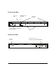
3 Front of the Hub Back of the Hub Hub Operation Hub Reference
Hub Reference Front of the Hub Hub status LEDs The hub status LEDs indicate whether the hub is functioning properly. For further details on error conditions indicated by the Status LEDs, see chapter 2, “Troubleshooting”. LED Power (green) Activity (green) State Meaning of LED On The hub is receiving power. Off The hub is not receiving power. Flickering ON while a packet is being transmitted. Normally, the LED appears to flicker. In heavy traffic, it may appear on all the time.
Hub Reference Port status LEDs The following table provides LED port information. If an HP AdvanceStack 8U/16U SNMP module is installed, additional LED states may be observed. For information about the hub LEDs when an HP AdvanceStack 8U/16U SNMP Module is installed, see the manual accompanying the module. LED AUI/Xcvr Port (green) State Meaning of LED On An optional HP Transceiver Module is properly installed in the hub’s front panel slot. Off An HP Transceiver Module is not installed.
Hub Reference Hub Operation The HP AdvanceStack Hub-16U is a multiport repeater that conforms to the IEEE 802.3 repeater specification. Data signals coming into the hub from any of its ports are automatically regenerated and transmitted to all the other hub network ports. The hub regenerates the data without interpreting the contents, so it can be used in either IEEE 802.3 or Ethernet networks and with any upper-level protocol. Collision Detection Hub Reference The hub also performs collision detection.
Hub Reference Auto-Partitioning The hub will automatically partition (temporarily disable) one of its ports if a collision condition exists for an excessive duration (between 1024 and 2048 bit times) or occurs during each of 32 consecutive attempts to transmit. The hub monitors the partitioned port and automatically re-enables the port when a minimum length packet can be successfully transmitted or received without a collision occurring. Excessive collisions may be caused by faulty wiring.
A Recommended Cables Twisted-Pair Cable/Connector Pin-Outs ThinLAN Requirements Cables and Connectors
Cables and Connectors This appendix lists cables that have been tested and verified for use with the HP AdvanceStack Hub-16U. It also includes minimum pin-out information so, if you wish to use an unlisted cable, you can verify that the cables used in your installation are correctly wired. Note that each pin-out does not necessarily match the pin-out for the corresponding HP cable, but cables manufactured to follow the minimum pin-out will function correctly.
Cables and Connectors Twisted-Pair Cable/Connector Pin-Outs Twisted-Pair Cable for Hub-to-Computer Network Connection To connect PCs or other network devices to the hub, use a “straight-through” 10Base-T cable. The twisted-pair wires must be twisted through the entire length of the cable. The wiring sequence must conform to AT&T 258A (not USOC). See “Twisted-Pair Cable Pin Assignments” later in this chapter for a listing of the signals used on each pin.
Cables and Connectors Twisted-Pair Cable Pin Assignments Twisted-Pair Straight-Through Cable Hub End Computer or Transceiver End Signal Pins Pins Signal (receive +) (receive –) (transmit +) (transmit –) 1 2 3 6 1 2 3 6 (transmit +) (transmit –) (receive +) (receive –) ThinLAN Cable Requirements If you add an HP J2608A ThinLAN Transceiver Module, the thin coaxial cables used with the module must comply with the IEEE 802.3 Type 10Base2 requirements.
B Physical Electrical Environmental Connectors Electromagnetic Specifications
Specifications Specifications Physical Width: 42.5 cm (16.8 in) Height: 4.36 cm (1.7 in) Depth: 23.8 cm (9.4 in) Weight: 2.2 kg (4.8 lb) Electrical 100 - 127 volts 200-240 volts Maximum current: ac voltage: 0.3A max 0.2A max Frequency range: 50/60 Hz 50/60 Hz Environmental Operating Non-Operating Temperature: 0°C to 55°C (32°F to 131°F) -40°C to 70°C (-40°F to 158°F) Relative humidity: (non-condensing) 15% to 95% at 40°C (104°F) 15% to 90% at 65°C (149°F) 4.6 km (15,000 ft) 4.
Safety and Regulatory Statements
Safety Information Safety Symbols Safety and Regulatory Statements Documentation reference symbol. If the product is marked with this symbol, refer to the product documentation to get more information about the product. WARNING A WARNING in the manual denotes a hazard that can cause injury or death. CAUTION A CAUTION in the manual denotes a hazard that can damage equipment.
Informations concernant la sécurité Symboles de sécurité Symbole de référence à la documentation. Si le produit est marqué de ce symbole, reportez-vous à la documentation du produit afin d’obtenir des informations plus détaillées. Dans la documentation, un WARNING indique un danger susceptible d’entraîner des dommages corporels ou la mort. CAUTION Un texte de mise en garde intitulé CAUTION indique un danger susceptible de causer des dommages à l’équipement.
Hinweise zur Sicherheit Sicherheitssymbole Safety and Regulatory Statements Symbol für Dokumentationsverweis. Wenn das Produkt mit diesem Symbol markiert ist, schlagen Sie bitte in der Produktdokumentation nach, um mehr Informationen über das Produkt zu erhalten. WARNING Eine WARNING in der Dokumentation symbolisiert eine Gefahr, die Verletzungen oder sogar Todesfälle verursachen kann. CAUTION CAUTION in der Dokumentation symbolisiert eine Gefahr, die das Gerät beschädigen kann.
Considerazioni sulla sicurezza Simboli di sicurezza Simbolo di riferimento alla documentazione. Se il prodotto è contrassegnato da questo simbolo, fare riferimento alla documentazione sul prodotto per ulteriori informazioni su di esso. La dicitura WARNING denota un pericolo che può causare lesioni o morte. CAUTION La dicitura CAUTION denota un pericolo che può danneggiare le attrezzature.
Consideraciones sobre seguridad Símbolos de seguridad Safety and Regulatory Statements Símbolo de referencia a la documentación. Si el producto va marcado con este símbolo, consultar la documentación del producto a fin de obtener mayor información sobre el producto. WARNING Una WARNING en la documentación señala un riesgo que podría resultar en lesiones o la muerte. CAUTION Una CAUTION en la documentación señala un riesgo que podría resultar en averías al equipo.
Safety Information Safety and Regulatory Statements 7
Regulatory Statements FCC Statement (For U.S.A. Only) Federal Communications Commission Radio Frequency Interference Statement Warning: This equipment generates, uses, and can radiate radio frequency energy. If it is not installed and used in accordance with the instruction manual, it may cause interference to radio communications.
Declaration of Conformity The following Declaration of Conformity for the HP AdvanceStack Hub-16U complies with ISO/IEC Guide 22 and EN 45014. The declaration identifies the product, the manufacturer’s name and address, and the applicable specifications that are recognized in the European community.
Index
! D 50-ohm terminator for a ThinLAN cable segment ... 1-15 Declaration of Conformity ... C-9 diagnosing with the LEDs ... 2-3 diagnostic tests ... 2-7 testing the hub only ... 2-8 testing twisted-pair cabling ... 2-8 A Activity LED ... 3-2 AUI/Xcvr LED ... 3-3 auto-partitioning basic operation ... 3-5 Index B back of the hub installing optional modules ... 1-3 BBS obtaining software from ... 2-11 bulletin board obtaining software from ... 2-11 C cabinet mounting instructions for ...
hub operation auto-partitioning ... 3-5 collision detection ... 3-4 description ... 3-4 link beat ... 3-5 verifying ... 1-6 hub to hub network connections with the MDI switch ... 1-13 I L LAN adapter cards to test end-to-end communications ... 2-9 LEDs Activity ... 3-2 AUI/Xcvr ... 3-3 Collision ... 3-2 diagnosing the hub status ... 2-3 pattern during self test ... 2-3 patterns showing error conditions ... 2-4 Power ... 3-2 twisted-pair ports ... 3-3 verifying hub operation ... 1-7 link beat description .
R rack mounting instructions for ... 1-9 recommended cables ... A-2 Regulatory statements ... C-8 replacement of the hub ... 2-10 resetting the hub troubleshooting procedure ... 2-8 RJ-45 jack ... 1-11 Index S Safety information ... C-2 specifications connectors ... B-2 electrical ... B-2 electromagnetic ... B-2 environmental ... B-2 physical ... B-2 status LEDs description ... 3-2 summary installation steps ... 1-2 T technical support types of ... 2-11 terminator for a thin LAN segment ...
Technical information in this document is subject to change without notice. © Copyright 1996 Hewlett-Packard Company Printed in U.S.A.