
Instruction Manual
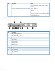
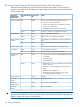
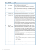

StatusDescriptionItem
Green = The switch self test and initialization are in progress after you have power
cycled or reset the switch. The switch is not operational until this LED goes off.
Self test LED6
Blinking green
1
= A component of the switch has failed its self test. The status LED
for that component, for example an RJ-45 port, and the switch Fault LED will blink
simultaneously.
Off = The normal operational state; the switch is not undergoing self test.
Blinking green
1
= The cooling fan has failed. The switch Fault LED will be blinking
simultaneously.
Fan status LED6
Off = The cooling fan is operating normally.
Press the button to step from one mode to the next. The current mode setting is
indicated by the Mode select LEDs near the button.
Mode select button7
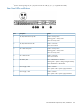
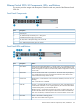
Act = Indicates that the port Mode LEDs are displaying network activity information.Mode select LEDs8
FDx = Indicates that the port Mode LEDs are lit for ports that are in Full Duplex
Mode.
Spd = Indicates that the port Mode LEDs are lit for ports that are operating at their
maximum possible link speed. For the 10/100TX ports, that is 100 Mbps.
! = Indicates that the port Mode LEDs are displaying network events that could
require operator attention, for example CRC errors or late collisions.
On = Indicates the port is enabled and receiving a link indication from the
connected device.
Link LED9, 10
Off = One of these conditions exists:
• No active network cable is connected to the port
• The port is not receiving link beat or sufficient light
• The port has been disabled through the switch console, the web browser
interface, or HP TopTools.
Blinking = If the LED is blinking simultaneously with the Fault LED, the corresponding
port has failed its self test.
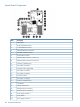
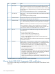
Displays network activity information, or whether the port is configured for Full
Duplex operation, or maximum link speed operation, or is experiencing network
events requiring operator intervention depending on the mode selected.
Mode LED9, 11
• If the Activity (Act) indicator LED is lit, each Mode LED displays activity
information for the associated port—it flickers as network traffic is received and
transmitted through the port.
• If the Full Duplex (FDx) indicator LED is lit, the Mode LEDs light for those ports
that are operating in full duplex.
• If the maximum speed (Max) indicator LED is lit, the Mode LEDs light for those
ports that are operating at their maximum possible link speed: 100 Mbps for
10/100 ports and 100-FX fiber-optic ports, and 1000 Mbps for
100/1000Base-T or gigabit fiber-optic ports.
• If the attention (!) indicator LED is lit, each Mode LED lights briefly for each
network event that could require operator attention, for example, late collisions
or CRC errors.
1
The blinking behavior is an on/off cycle once every 1.6 seconds, approximately.
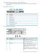
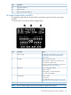
Ethernet Switch 2810–24G Components, LEDs, and Buttons
This section provides images and descriptions of the front and rear panels of the Ethernet Switch
2810–24G.
158 Component Identification