
Instruction Manual
3. Stop any in-process backups and restores, and disable the VLS in the backup applications to
suspend operations during the node replacement.
4. Create a firmware version 6.1.0 Quick Restore DVD. Having one DVD for each node will
speed up the Quick Restore process.
To replace the nodes:
1. Attach rails to all of the replacement VLS9200 nodes; see the instructions in the rail kit.
2. As a best practice, save the configuration on the live VLS system.
3. Shut down all VLS nodes. You will start the replacements with the master node.
4. Disconnect all power cords from the node.
5. From the back of the node, make a note of all cable connections then disconnect the cables.
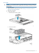
6. Remove the node from the front of the chassis. See “Replacing a Primary Node” (page 173)
for details.
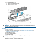
7. Install the replacement VLS9200 node into the rack.
8. Reconnect the cables to the new node.
The VLS9200 master node does not need the USB dongle. The Ethernet switch cables should
now connect to NIC ports 3 and 4.
9. Reconnect the power cords to the node.
10. Power up the node.
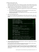
11. Insert the Quick Restore DVD into the drive and start the Quick Restore process. When the
Quick Restore is complete, the node will automatically reboot.
12. Repeat Step 4 through Step 11 for all secondary nodes.
13. When the master node comes up after the reboot, configure it as you would configure a new
VLS installation. See “Configuring the Primary Node 0” (page 22) for details. The node will
reboot after the configuration is set.
14. After the master node comes up after the reboot, configure each secondary node as you would
configure a new VLS installation. See “Configuring the Secondary Nodes” (page 22) for
details.
15. Log into Command View VLS to ensure that all secondary nodes have come up. (It does not
matter if they show a degraded state.)
16. Install the hp_6.1.0_reboot_3053 patch to the system; this will adjust the new backend Ethernet
configuration on each node. See the HP Virtual Library System hp_6.1.0_reboot_3053 Patch
Release Notes for details.
17. After the automatic reboot from the patch, log back into Command View VLS.
18. If any of the secondary nodes show a degraded state, run the Clear All Faults task on the
Chassis screen.
All nodes should now be up and in the green Good state.
Ethernet Switch Replacement
To replace an Ethernet Switch:
1. Power off the switch.
2. Make a note of all cable connections to the switch then disconnect the cables.
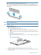
3. From the front of the switch, loosen the captive thumbscrews until the thumbscrews are free of
the rack.
4. Remove the switch from the rack.
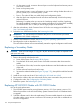
5. Install the new switch into the rack. See “Installing the Ethernet Switch 6600–24G into a
Rack” (page 18).
6. Reconnect all cables to the new switch exactly as they were connected to the failed switch.
7. Power on the new switch.
Ethernet Switch Replacement 175