
Manual
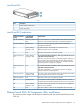
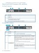
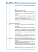
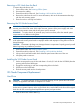

Front Panel Components
DescriptionItem
Console port1
10/100Base-TX RJ-45 Ethernet ports 1 through 24
(numbered from left to right, top to bottom)
2
10/100/1000–T dual-personality ports 25 and 263
mini—GBIC dual-personality ports 25 and 264
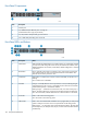
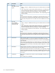
Front Panel LEDs and Buttons
StatusDescriptionItem
When pressed with the Reset button in a specific pattern, any configuration changes
you may have made through the switch console, the web browser interface, and
Clear button1
SNMP management are removed, and the factory default configuration is restored
to the switch.
Press to reset the switch while it is powered on. This action clears any temporary
error conditions that may have occurred and executes the switch self test. Also
resets all network activity counters to zero.
Reset button2
Blinking blue = Locate function is active. Firmware controlled, can be set to on or
blinking.
Locator LED3
Off = Locate function is disabled.
Orange = On briefly after the switch is powered on or reset, at the beginning of
switch self test. If this LED is on for a prolonged time, the switch has encountered
a fatal hardware failure, or has failed its self test.
Fault LED4
Blinking orange
1
= A fault has occurred on the switch, one of the switch ports, or
the fan. The Status LED for the component with the fault will blink simultaneously.
Off = The normal state; indicates that there are no fault conditions on the switch.
Green = The switch is receiving power.Power LED5
Off = The switch is NOT receiving power.
Green = The switch self test and initialization are in progress after you have power
cycled or reset the switch. The switch is not operational until this LED goes off.
Self test LED6
Blinking green
1
= A component of the switch has failed its self test. The status LED
for that component, for example an RJ-45 port, and the switch Fault LED will blink
simultaneously.
152 Component Identification