
Manual

NOTE: If your rack contains single phase PDUs:
• Install up to four nodes in the first rack starting in position 35 working up the rack.
• Install up to four nodes in the second rack starting in position 35 working up the rack.
If your rack contains 3–phase PDUs:
• Install up to six nodes in the first rack starting in position 33 working up the rack.
• Install up to two nodes in the second rack starting in position 33 working up the rack.
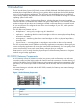
Cabling the VLS Node
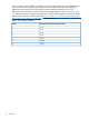
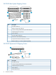
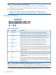
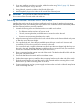
Table 2 Cabling the Node
Connects toDescriptionItem
Primary node: connects to your system's backend storage via FC cable.FC port 41
Secondary nodes: connects to your system's backend storage via FC cable.
Primary node: connects to your system's backend storage via FC cable.FC port 32
Secondary nodes: connects to your system's backend storage via FC cable.
Primary node: connects to your system's backup SAN via FC cable.FC port 23
Secondary nodes: connects to your system's backup SAN via FC cable.
Primary node: connects to your system's backup SAN via FC cable.FC port 14
Secondary nodes: connects to your system's backup SAN via FC cable.
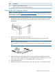
Primary node: connects to port 1 of Ethernet switch #2 (SW2) via Ethernet cable.NIC 45
Secondary nodes: connects to the next available port on Ethernet switch #2 (SW2)
via Ethernet cable. Cable secondary nodes to the switch ports 2 through 8 in
sequential order.
Primary node: connects to port 1 of Ethernet switch #1 (SW1) via Ethernet cable.NIC 36
Secondary nodes: connects to the next available port on Ethernet switch #1 (SW1)
via Ethernet cable. Cable secondary nodes to the switch ports 2 through 8 in
sequential order.
Primary node: connects to your system's external network via Ethernet cable.NIC 17
Secondary nodes: connects to your system's external network when using replication
via Ethernet cable.
NOTE: Not all systems use all of the components listed in Table 2 (page 18).
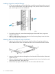
The primary node, node 0, is on the bottom of the stack of nodes. From the bottom to the top they
are: node 0, node 1, node 2, node 3. (The number of nodes will vary from system to system.)
1. Cable the primary node (node 0) and secondary node (node 1) using Table 2 (page 18).
18 Hardware Installation