Hardware Reference Guide HP Engage One Retail System, Model 141 HP Engage One Retail System, Model 143 HP Engage One Retail System, Model 145
© Copyright 2018 HP Development Company, L.P. ENERGY STAR® is a registered mark owned by the U.S. government. Intel, Celeron, and Core are trademarks of Intel Corporation in the United States and/or other countries. Windows is either a registered trademark or trademark of Microsoft Corporation in the United States and/or other countries. The information contained herein is subject to change without notice.
About This Guide This guide provides basic information for upgrading this computer model. WARNING! Indicates a hazardous situation that, if not avoided, could result in death or serious injury. CAUTION: Indicates a hazardous situation that, if not avoided, could result in minor or moderate injury. IMPORTANT: Indicates information considered important but not hazard-related (for example, messages related to property damage).
iv About This Guide
Table of contents 1 Product overview .......................................................................................................................................... 1 Standard features .................................................................................................................................................. 1 Integrated features ................................................................................................................................................
Installing a security screw on the Engage One head unit and VESA mount ....................................................... 30 Removing the display panel ................................................................................................................................ 31 Replacing the display panel ................................................................................................................................. 32 System board components ......................................
Shipping preparation ........................................................................................................................................... 55 Appendix D Accessibility ................................................................................................................................. 56 Supported assistive technologies ....................................................................................................................... 56 Contacting support ...............
viii
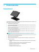
1 Product overview Standard features The HP Engage One Retail System is designed for long-term deployment within general retail, hospitality, and other markets. It includes the following features: ● Integrated All-in-One (AiO) form factor ● 14-inch diagonal display panel (wide-aspect ratio); FHD 1920 x 1080 resolution, sealed and chemically hardened, anti-glare; anti-smudge ● Model 141: anti-glare WLED SVA 300-nit panel with FHD 1920 x 1080 resolution and an Intel® Celeron® 3965U 2.
● DDR4 2400 MHz memory with up to 32 GB RAM ● Operating system choices: ● ● 2 – Windows® 10 IoT Enterprise 2016 LTSB 64-bit – Windows 10 Professional 64-bit – FreeDOS 2.0 HP Engage One Advanced I/O Connectivity Base (optional) – 2 powered serial ports (0 V, 5 V, 12 V) – (2) 12 V powered USB ports – (1) 24 V powered USB port – 4 USB 3.
Integrated features The integrated devices shown below are optional.
Stand options Options (1) HP Engage One Rotate/Tilt Stand with Integrated Column Printer (2) HP Engage One Rotate/Tilt Stand (3) HP Engage One Fixed Position Stand NOTE: The stands are shown on a stability base. HP Engage One Basic I/O Connectivity Base components Basic components (1) Cash drawer jack (7) USB Type-C port (2) Power connector (8) RJ-45 network jack (3) USB Type-C power port (9) Security cable slot (4) Powered serial ports (3) (10) MicroSD card reader (5) USB 2.
HP Engage One Advanced I/O Connectivity Base components Advanced components (1) Cash drawer jack (7) USB 3.0 ports (4) (2) Powered USB 12 V ports (2) (8) USB Type-C port (3) Powered USB 24 V port (9) RJ-45 network jack (4) Power connector (10) Security cable slot (5) USB Type-C power port (11) MicroSD card reader (6) Powered serial ports (2) (12) Headset jack IMPORTANT: drawer jack.
Connecting an AC adapter to power To connect an AC adapter to the I/O connectivity base, connect one end of the power cord to the AC adapter (1) and the other end to a grounded AC outlet (2), and then connect the AC adapter to the power connector on the I/O connectivity base (3).
Locating the Engage One power button The computer power button is located on the bottom right edge of the bezel. Locating the I/O connectivity base power button The I/O connectivity base power button is located on the underside of the I/O connectivity base. The head unit controls the I/O connectivity base. When the head unit is turned off, the I/O connectivity base is turned off and power is not available from the I/O connectivity base ports.
Adjusting the Engage One head unit NOTE: The tilt and swivel features are only available on performance stands. You can tilt and swivel the computer head to set it to a comfortable viewing angle. There is a 10° tilt range that can be set between 50° and 60°. The computer head unit can be swiveled 180° in either direction.
Engage One serial number location Each computer has a unique serial number and a product ID number that are located on the exterior of the computer. Keep these numbers available for use when contacting customer service for assistance. I/O connectivity base serial number location Each I/O connectivity base has a unique serial number and a product ID number that are located on the exterior of the I/O connectivity base. Keep these numbers available for use when contacting customer service for assistance.
2 Cable routing configurations Cable matrix for Engage One with integrated column printer and basic I/O connectivity base Cables 10 (1) Column printer AC power cord (5) I/O connectivity base mini USB Type-B to USB Type-A data cable (2) Column printer AC adapter cable (6) I/O connectivity base USB Type-C cable (3) Cash drawer cable (purchased separately with cash drawer) (7) I/O connectivity base 120 W AC power cord (4) Column printer cash drawer cable Chapter 2 Cable routing configuration
Cable matrix for Engage One with integrated column printer and advanced I/O connectivity base Cables (1) I/O connectivity base 180 W AC power cord (4) Column printer 24 V PUSB power and data Y cable (2) Cash drawer cable (purchased separately with cash drawer) (5) I/O connectivity base USB Type-C cable (3) Column printer cash drawer cable Cable matrix for Engage One with integrated column printer and advanced I/O connectivity base 11
Cable matrix for Engage One without I/O connectivity base Cables (1) 12 PC power cord Chapter 2 Cable routing configurations
Cable matrix for Engage One with I/O connectivity base Cables (1) Basic I/O connectivity base 120 W AC power cord (4) USB-C mini dock 90 W AC power cord (2) I/O connectivity base USB Type-C cable (5) USB-C mini dock captive USB Type-C cable (3) Advanced I/O connectivity base 180 W AC power cord NOTE: In the European region, the USB-C mini dock is sold as an aftermarket option kit only. In all other regions, the USB-C mini dock is sold as drop-in-box option.
Cable matrix for Engage One with basic I/O connectivity base and standalone printer Cables (1) Printer AC power cord (4) Printer USB Type-A to Type-B data cable (2) Basic I/O connectivity base 120 W AC power cord (5) Basic I/O connectivity base USB Type-C cable (3) Printer serial data cable IMPORTANT: Connect either the serial data cable (3) or the USB Type-A data cable (4) between the I/O connectivity base and the printer. Do not connect both.
Cable matrix for Engage One with advanced I/O connectivity base and standalone printer Cables (1) Printer 24 V PUSB power and data “Y” cable (4) Printer serial data cable (2) Advanced I/O connectivity base 180 W AC power adapter cord (5) Advanced I/O connectivity base USB Type-C cable (3) Printer 24 V PUSB power cable IMPORTANT: Connect either the 24 V PUSB power and data “Y” cable (1) or the 24 V PUSB power cable (3) and serial data cable (4) between the I/O connectivity base and the printer.
3 Hardware configurations and upgrades Tools needed A Phillips screwdriver can be used for procedures described in this guide. Warnings and cautions Before performing upgrades be sure to carefully read all of the applicable instructions, cautions, and warnings in this guide. WARNING! To reduce the risk of personal injury from electric shock, hot surfaces, or fire: Disconnect the power cord from the AC outlet before removing the enclosure. Energized parts are inside.
Attaching an I/O connectivity base to the Engage One You can attach an I/O connectivity base to the bottom of the computer’s stand. 1. Turn off the computer properly through the operating system, and turn off any external devices. 2. Disconnect the power cords from the computer and I/O connectivity base. IMPORTANT: Regardless of the power-on state, voltage is always present on the system board as long as the system is plugged into an active AC outlet.
18 5. Place the I/O connectivity base onto the bottom of the stand (1), and then tighten the four screws on the underside of the I/O connectivity base (2) to secure the I/O connectivity base to the stand. Be sure that the USB Type-C power cable is routed through the gap between the back of the I/O connectivity base and the stand. 6.
Connecting a standalone I/O connectivity base to the Engage One 1. Turn off the computer properly through the operating system, and turn off any external devices. 2. Disconnect the power cords from the computer and I/O connectivity base. IMPORTANT: Regardless of the power-on state, voltage is always present on the system board as long as the system is plugged into an active AC outlet.
1. Turn off the computer properly through the operating system, and turn off any external devices. 2. Disconnect the power cord and all peripheral devices from the I/O connectivity base. IMPORTANT: Regardless of the power-on state, voltage is always present on the system board as long as the system is plugged into an active AC outlet. You must disconnect the power cord and wait approximately 30 seconds for the power to drain to avoid damage to the internal components of the I/O connectivity base. 20 3.
5. Place the bottom plate onto the I/O connectivity base (1), and then secure the plate to the I/O connectivity base with the five screws (2). 6. Reconnect the I/O connectivity base’s power cord and peripheral devices. Connecting a standalone optional fingerprint reader to the I/O connectivity base The optional fingerprint reader can be used as a standalone device or it can be attached to the I/O connectivity base.
3. Connect the USB cable to the fingerprint reader (1) and route the cable through the routing channel (2) on the fingerprint reader. 4. Connect the fingerprint reader USB cable to a USB Type-A port on the I/O connectivity base. 5. Reconnect the I/O connectivity base and computer power cords. Attaching an optional fingerprint reader to the I/O connectivity base The optional fingerprint reader can be used as a standalone device or it can be attached to the I/O connectivity base.
3. Place the fingerprint reader (1) on the riser (2), and then attach the mounting bracket (3) and cable routing clip (4) to the fingerprint reader and riser with the two long screws (5) included with the fingerprint reader. 4. Connect the USB cable to the fingerprint reader (1) and route the cable under the routing clip on the fingerprint reader (2).
5. Connect the fingerprint reader cable to a USB Type-A port on the I/O connectivity base. 6. Reconnect the I/O connectivity base and computer power cords. Removing the Engage One head unit from the stand 1. Turn off the computer properly through the operating system, and turn off any external devices. 2. Disconnect the power cord from the computer. IMPORTANT: Regardless of the power-on state, voltage is always present on the system board as long as the system is plugged into an active AC outlet.
Attaching the Engage One head unit to the stand 1. Turn off the computer properly through the operating system, and turn off any external devices. 2. Disconnect the power cord from the computer. IMPORTANT: Regardless of the power-on state, voltage is always present on the system board as long as the system is plugged into an active AC outlet. You must disconnect the power cord and wait approximately 30 seconds for the power to drain to avoid damage to the internal components of the computer. 3.
You also have the option of routing the USB Type-C cable out the rear of the VESA bracket and through a wall instead of attaching a USB Type-C cable to the port on the side of the bracket. 4. 26 a. Press the rear cover release tab (1) on the VESA bracket, and then pull the rear cover off the VESA bracket (2). Unplug the cable from the inside of the VESA bracket. b.
Mounting the Engage One to a counter top You can use an optional counter top mounting bracket to mount the computer head unit and column to a counter top. NOTE: The mounting bracket requires an 80 mm hole in the counter top. The thickness of the counter top must be 10 mm to 50 mm. 1. If the stand’s base is attached to the column, remove the screw on the underside of the column (1), and then remove the base from the column (2). 2.
28 3. Hold the top piece of the mounting bracket against the bottom of the column, route the cables through the hole in the mounting surface, and then place the column over the hole on the mounting surface. 4. The bottom piece of the mounting bracket can be oriented in two ways, depending on the thickness of your mounting surface. Orient the bracket properly for your application before attaching it. 5. Route the cables through the hole in the bottom piece of the mounting bracket (1).
Installing a security cable on the I/O connectivity base You can secure the I/O connectivity base to a fixed object with an optional Keyed Cable lock security cable extension and an optional security cable available from HP. NOTE: The security cable is sold separately as an aftermarket option kit only.
Installing a security screw on the Engage One head unit and stand You can insert a tamper-resistant security screw into the computer’s column with a T-10 screwdriver to prevent access to the computer head unit’s release button. 1. Remove the security screw from the bottom of the stand’s column. 2. Install the security screw in the release button hole on the stand’s column.
2. Press the head unit onto the VESA mount (1) if it is not already attached, and then install the security screw (2) in the release button hole on the VESA mount. Removing the display panel You must remove the display panel from the computer head unit to access internal computer components. 1. Turn off the computer properly through the operating system, and turn off any external devices. 2. Disconnect the power cord from the computer.
5. Separate the computer’s display panel from the computer head unit at the connection points, and then lift the display panel up approximately 2.5 cm (one inch). IMPORTANT: Do not lift the display panel higher than 2.5 cm (one inch) from the computer head unit. An internal cable must be disconnected before the display panel can be fully removed. 6. Holding the display panel 2.5 cm (one inch) from the computer head unit, shift the display panel forward no more than 7.
IMPORTANT: Be sure that the touch and WLAN cables are connected between the top of the display panel and the top of the computer head unit. 2. Hold the display panel 2.5 cm (one inch) above the computer head unit with the display panel shifted forward 7.5 cm (three inches) (1). Connect the display cable to the display connector on the system board (2), and then press down the edges of the tape so that it adheres to the system board. 3.
System board components Refer to the table below to locate the system board components referenced in this guide. System board components (1) SD card slot (4) WLAN module (2) CFD connector (5) M.2 SSD (3) Memory modules Installing a 2 x 20 customer-facing display (CFD) 1. Turn off the computer properly through the operating system, and turn off any external devices. 2. Disconnect the power cord from the computer.
5. Remove the rubber stoppers from the CFD cable routing channel and the two CFD screw holes. 6. Route the CFD cable through the routing channel on the computer head unit (1). Pull the cable all the way through the channel (2), and then slide the screw tabs on the CFD into the slots on the computer head unit (3).
7. Install the two screws that attach the CFD to the computer head unit (1), and then connect the CFD cable to the connector on the system board (2). IMPORTANT: Make sure the entire CFD cable is pulled all the way through the head unit routing channel before installing the CFD so that the cable does not get pinched between the CFD and the head unit. 8. Replace the computer head unit’s display panel. See Replacing the display panel on page 32. 9. Attach the computer head unit to the stand.
Installing memory The computer comes with at least one preinstalled double data rate 4 synchronous dynamic random access memory (DDR4-SDRAM) small outline dual in-line memory module (SODIMM). There are two memory sockets on the system board that can be populated with up to 32 GB of memory. DDR4-SDRAM SODIMMs For proper system operation, the memory modules must be 1.
38 5. Remove the shield over the memory modules by pulling the tab on the shield up (1), and then lifting the shield from the system board (2). 6. To remove a memory module, press outward on the two latches on each side of the memory module (1), and then pull the memory module out of the socket (2).
7. To install a memory module, slide the new memory module into the socket at approximately a 30° angle (1), and then press the memory module down into the socket (2) so that the latches lock it in place. NOTE: A memory module can be installed in only one way. Match the notch on the module with the tab on the memory socket. 8. Replace the shield over the memory modules by pressing the left side of the shield down onto the system board (1) and then the pressing the right side down (2). 9.
Removing and installing an M.2 solid-state drive (SSD) IMPORTANT: If you are replacing an SSD, be sure to back up the data from the old SSD so that you can transfer the data to the new SSD. 1. Turn off the computer properly through the operating system, and turn off any external devices. 2. Disconnect the power cord from the computer. IMPORTANT: Regardless of the power-on state, voltage is always present on the system board as long as the system is plugged into an active AC outlet.
6. To install an SSD, slide the connector end of the SSD into the system board connector (1), and then secure the other end of the SSD to the system board with the screw (2). 7. Replace the computer head unit’s display panel. See Replacing the display panel on page 32. 8. Attach the computer head unit to the stand. See Attaching the Engage One head unit to the stand on page 25 9. Reconnect the power cord and press the power button. Inserting an internal SD card 1.
5. Insert the SD card into the SD card slot on the system board. 6. Replace the computer head unit’s display panel. See Replacing the display panel on page 32. 7. Attach the computer head unit to the stand. See Attaching the Engage One head unit to the stand on page 25 8. Reconnect the power cord and press the power button. Removing and installing a WLAN module 1. Turn off the computer properly through the operating system, and turn off any external devices. 2.
5. To remove a WLAN module, disconnect the WLAN cables (1), remove the screw (2) that secures the module to the system board, and then slide the module out of the system board connector (3). IMPORTANT: The WLAN cables and connectors are labeled 1 and 2. Make sure that you match the numbered labels on the WLAN module with the numbered labels on the cables when reconnecting the cables. 6.
4 Using the column printer The column printer is an optional component that may be included with your system.
When to change the receipt paper Change the paper when it is near the end of the roll or when the roll is empty. When the paper is low, you must monitor usage to avoid running out part of the way through a transaction. When the roll is empty, you must load a new roll immediately or data may be lost. ● When the paper is low, a colored stripe appears on the receipt paper (if the paper purchased has a stripe) indicating that enough paper remains for a small transaction.
5. To test that the paper is loaded correctly, advance the paper with the paper feed button (1), and then tear the excess paper off against the knife on the cover. A steady green LED (2) means the printer is on and operating normally. If the LED is flashing, the cover may not be completely shut. Thermal paper specifications The printer requires qualified thermal paper with the following dimensions: ● Width: 80 +0/-0.6 mm (3.15 +0/-0.03") ● Diameter: 50.8 mm max.
Qualified manufacturers Phone/Fax Paper grade Kanzaki Specialty Papers (USA) Voice: (888) 526–9254 20 Cummings St. Fax: (413) 731–8864 P30023 (was P–300), P31023 (was P–310), Kauttua, Finland http://www.jujothermal.com/ Ware, MA 01082–2002 http://www.kanzakiusa.com/ P35024 (was P–350), P35032 (was P–354), P39023 (BPA free, was P–390), P30521 (BPA free), P30523 (BPA free), P31523 (BPA free), P35532 (BPA free) Koehler UK Ltd.
Printer tone and green LED Condition Possible causes Possible solutions Where to go for more information Green LED, quick steady flashing. Paper roll is empty. Load a new paper roll. See Loading the printer receipt paper on page 45. Receipt cover is open. Close the cover. If the problem persists, continue opening and closing the cover until the LED stops blinking. The knife is unable to return to the home position. Stop using the printer. Contact your authorized HP service representative.
Condition Possible causes Possible solutions Where to go for more information Stop using the printer. Contact your authorized HP service representative. electronics or missing dot on printhead. One side of receipt is missing. NOTE: This indicates a serious condition with the printer electronics. Using nonrecommended paper may damage the printhead and void the warranty. Printer does not function Condition Possible causes Possible solutions Printer does not function when turned on and LED is off.
Latch failsafe In the event that the receipt cover becomes stuck, the printer has a failsafe to release the cover’s latches. Using a thin pointed object, press the rectangular button adjacent to the printhead. With enough pressure, the latches should release, and the receipt cover should open. Cleaning the printer Because of the way the printer sits while in use, it is likely there will be buildup of paper and other debris from the knife.
5 Configuring the software Touch screen calibration for Windows 10 Professional and Windows 10 IoT Enterprise for Retail NOTE: The Windows calibration tool works only in digitizer touch mode. If you install a retail touch utility, it will set the touch screen to POS mode (mouse mode) by default and will not allow the Windows calibration tool to run. To calibrate the touch module in Windows 10 Professional and Windows 10 IoT Enterprise for Retail: 1. Open Control Panel.
A Enabling encryption on the MSR The MSR designed into the Engage One terminal has an optional encryption functionality. HP has partnered with IDTECH Products to perform key injection services remotely. For more information about their service, contact the IDTECH Products sales team at Sales@idtechproducts.com.
B Electrostatic discharge A discharge of static electricity from a finger or other conductor may damage system boards or other staticsensitive devices. This type of damage may reduce the life expectancy of the device. Preventing electrostatic damage To prevent electrostatic damage, observe the following precautions: ● Avoid hand contact by transporting and storing products in static-safe containers. ● Keep electrostatic-sensitive parts in their containers until they arrive at static-free workstations.
C Computer operating guidelines, routine care, and shipping preparation Computer operating guidelines and routine care Follow the guidelines below to properly set up and care for the computer: ● HP recommends a 17 mm clearance around the vents on the computer head unit and I/O connectivity base for heat dissipation. ● Keep the computer away from excessive moisture, direct sunlight, and extremes of heat and cold. ● Never operate the computer with any access panels removed.
MSR maintenance To clean the MSR (magnetic strip reader), swipe a standard cleaning card through the MSR a couple of times. You can order a standard cleaning card online. You can also put a thin oil-free cloth around a credit card. Shipping preparation Follow these suggestions when preparing to ship the computer: 1. Back up the hard drive files. Be sure that the backup media is not exposed to electrical or magnetic impulses while stored or in transit.
D Accessibility HP designs, produces, and markets products and services that can be used by everyone, including people with disabilities, either on a stand-alone basis or with appropriate assistive devices. Supported assistive technologies HP products support a wide variety of operating system assistive technologies and can be configured to work with additional assistive technologies. Use the Search feature on your device to locate more information about assistive features.
Index A accessibility 56 C cable routing configurations 10 CFD 34 column printer changing paper 45 cleaning 50 features 44 latch failsafe 50 paper specifications 46 qualified paper grades 46 troubleshooting 47 computer operating guidelines 54 connecting AC adapter 6 counter top mount 27 basic components 4 connecting power 6 installation guidelines 16 installing CFD 34 memory 37 SD card 41 SSD 40 WLAN module 42 V VESA mount 25 W warnings and cautions WLAN module 42 M memory installing 37 specifications