Hardware Reference Guide HP Engage Flex Pro Retail System HP Engage Flex Pro-C Retail System
© Copyright 2018 HP Development Company, L.P. The information contained herein is subject to change without notice. The only warranties for HP products and services are set forth in the express warranty statements accompanying such products and services. Nothing herein should be construed as constituting an additional warranty. HP shall not be liable for technical or editorial errors or omissions contained herein.
About This Guide This guide provides basic information for upgrading the HP EliteDesk Business PC. WARNING! Indicates a hazardous situation that, if not avoided, could result in death or serious injury. CAUTION: Indicates a hazardous situation that, if not avoided, could result in minor or moderate injury. IMPORTANT: Indicates information considered important but not hazard-related (for example, messages related to property damage).
iv About This Guide
Table of contents 1 Product features ........................................................................................................................................... 1 Standard configuration features ........................................................................................................................... 1 HP Engage Flex Pro ................................................................................................................................................
Preparing to remove a hard drive ................................................................................... 39 HP Engage Flex Pro ......................................................................................................... 40 Removing the hard drive below the optical drive ........................................ 40 Removing the hard drive below the power supply ...................................... 41 HP Engage Flex Pro-C ..............................................................
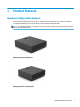
1 Product features Standard configuration features Features may vary depending on the model. For support assistance and to learn more about the hardware and software installed on your computer model, run the HP Support Assistant utility. NOTE: The HP Engage Flex Pro-C computer can be used in a tower orientation with an optional tower stand that can be purchased from HP.
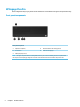
HP Engage Flex Pro Drive configuration may vary by model. Some models have a bezel blank covering the slim optical drive bay. Front panel components Front panel components 1 Optical drive (optional) 4 Network interface card activity lights (2) 2 Power button 5 Hard drive activity light 3 USB SuperSpeed ports (2) NOTE: The light on the power button is normally white when the power is on. If it is flashing red, there is a problem with the computer and it is displaying a diagnostic code.
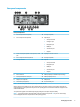
Rear panel components Rear panel components 1 PCIe x16 expansion slot (optional) 10 Serial port (optional) 2 PCIe x4 expansion slot (optional) 11 Optional port ● Serial port (shown) ● USB Type-C port ● DisplayPort port ● HDMI port ● 2nd ethernet port ● VGA port 3 Audio-out (headphone)/Audio-in (microphone) combo jack 12 DisplayPort monitor connector 4 PCIe x1 expansion slots (2) (optional) 13 Serial port (optional) 5 Security cable slot 14 Optional ● Serial port (shown) ● D
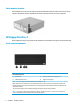
Serial number location Each computer has a unique serial number and a product ID number that are located on the exterior of the computer. Keep these numbers available for use when contacting customer service for assistance. HP Engage Flex Pro-C Drive configuration may vary by model. Some models have a bezel blank covering the slim optical drive bay.
Rear panel components Rear panel components 1 Serial port (optional) 9 Optional port ● Serial port (shown) ● USB Type-C port ● DisplayPort port ● HDMI port ● 2nd ethernet port ● VGA port 2 Security cable slot 10 DisplayPort port 3 USB Port, 24V (optional) 11 Optional port ● Serial port (shown) ● DisplayPort port ● HDMI port ● 2nd ethernet port ● VGA port 4 Cash drawer port (optional) 12 USB SuperSpeed port with HP Sleep and Charge 5 Audio-out (headphone)/Audio-in (micro
Serial number location Each computer has a unique serial number and a product ID number that are located on the exterior of the computer. Keep these numbers available for use when contacting customer service for assistance.
2 Hardware upgrades Serviceability features The computer includes features that make it easy to upgrade and service. A Torx T15 or flat-bladed screwdriver is needed for some of the installation procedures described in this chapter. Warnings and cautions Before performing upgrades be sure to carefully read all of the applicable instructions, cautions, and warnings in this guide.
Changing from desktop to tower orientation The HP Engage Flex Pro-C computer can be used in a tower orientation with an optional tower stand that can be purchased from HP. NOTE: To stabilize the computer in a tower orientation, HP recommends the use of the optional tower stand. 1. Remove/disengage any security devices that prohibit moving the computer. 2. Remove all removable media, such as compact discs or USB flash drives, from the computer. 3.
Removing the computer access panel To access internal components, you must remove the access panel. 1. Remove/disengage any security devices that prohibit opening the computer. 2. Remove all removable media, such as compact discs or USB flash drives, from the computer. 3. Turn off the computer properly through the operating system, and turn off any external devices. 4. Disconnect the power cord from the AC outlet and disconnect any external devices.
Removing the front bezel 1. Remove/disengage any security devices that prohibit opening the computer. 2. Remove all removable media, such as compact discs or USB flash drives, from the computer. 3. Turn off the computer properly through the operating system, and turn off any external devices. 4. Disconnect the power cord from the AC outlet and disconnect any external devices.
Removing an optical drive bezel blank On the HP Engage Flex Pro computer, a bezel blank covers the optical drive bay. Remove the bezel blank before installing an optical drive. To remove the bezel blank: 1. Remove the computer access panel. See Removing the computer access panel on page 9 for more information. 2. Remove the front bezel. See Removing the front bezel on page 10 for more information. 3.
Removing and installing the optional front bezel dust filter Some models are equipped with an optional front bezel dust filter. You must periodically clean the dust filter so that the dust collected on the filter does not impede air flow through the computer. NOTE: The optional front bezel dust filter is available from HP. To remove, clean, and replace the dust filter: 1. Turn off the computer properly through the operating system, and turn off any external devices. 2.
System board connections Refer to the following illustration and table to identify the system board connectors for your model. Item System board connector System board label Color Component 1 PCI Express x16 X16PCIEXP Black Expansion card slot 2 PCI Express x4 X4PCIEXP_1 Black Expansion card slot 3 PCI Express x2 X4PCIEXP_3 Black Expansion card slot 4 Riser Riser White Riser card slot 5 PCI Express x2 X4PCIEXP_2 Black Memory module 6 Battery BAT Black Battery 7 M.
Upgrading system memory The computer comes with double data rate 4 synchronous dynamic random access memory (DDR4-SDRAM) dual inline memory modules (DIMMs). The memory sockets on the system board are populated with at least one preinstalled memory module. To achieve the maximum memory support, you can populate the system board with up to 64 GB of memory configured in a high-performing dual-channel mode.
DIMM and one 1 GB DIMM, and Channel B should be populated with the other two 1 GB DIMMs. With this configuration, 4 GB will run as dual-channel and 1 GB will run as single-channel. ● In any mode, the maximum operational speed is determined by the slowest DIMM in the system. IMPORTANT: You must disconnect the power cord and wait approximately 30 seconds for the power to drain before adding or removing memory modules.
16 7. If you have the Engage Flex Pro, rotate the drive cage to its upright position to access the memory module sockets on the system board. 8. If you have the Engage Flex Pro-C, pull the CPU cover straight up and out of the chassis to access the memory module sockets on the system board.
9. Open both latches of the memory module socket (1), and insert the memory module into the socket (2). Press the module down into the socket, ensuring that the module is fully inserted and properly seated. Make sure the latches are in the closed position (3). NOTE: A memory module can be installed in only one way. Match the notch on the module with the tab on the memory socket. Populate the black DIMM sockets first. Then populate the white DIMM sockets.
12. If you have the Engage Flex Pro-C, align the tabs on the upper edges of the CPU cover (1) with the slots on the inside of the front panel and press the CPU cover straight down (2) onto the system board. 13. Replace the computer access panel. See Replacing the computer access panel on page 9 for more information. 14. If the computer was on a stand, replace the stand. See Changing from desktop to tower orientation on page 8 for more information. 15.
Removing or installing an expansion card Installing a half-height expansion card The computer system board has a PCI Express x16 expansion slot, a PCI Express x16 expansion slot that is downshifted to a x4 slot, a DisplayPort expansion slot, and a riser card expansion slot. The riser card expansion slot is populated with a riser card specifically designed for this product. NOTE: The PCI Express sockets support only low-profile cards.
Installing a 12-volt Powered USB expansion card The computer may be equipped with a 24-volt Powered USB connector on the riser card and may have one or two 12-volt Powered USB half-height expansion cards installed for a total of 6 optional 12-volt Powered USB ports. The 24-volt Powered USB connector and the 12-volt Powered USB connector are keyed differently as a precaution to prevent connection errors. NOTE: The 24-volt Powered USB connector is red. The 12-volt Powered USB connector is teal. 1.
a. If you are installing an expansion card in a vacant socket, remove the appropriate expansion slot cover on the back of the chassis. Pull the slot cover away from the side (1) of the chassis and then up and out (2) of the chassis. b. If you are removing a PCI Express card from the black PCI Express x16 socket that is downshifted to a x4 socket, hold the card at each end and carefully rock it back and forth until the connectors pull free from the socket. c.
d. If you are removing a PCI Express card from the black PCI Express x16 socket, pull the retention arm on the back of the expansion socket away from the card and carefully rock the card back and forth until the connectors pull free from the socket. Pull the card straight up from the socket and then away from the inside of the chassis to remove it from the chassis frame. Be sure not to scrape the card against other components.
11. Rotate the slot cover retention latch back into place to secure the expansion card. 12. Replace the computer access panel. See Replacing the computer access panel on page 9 for more information. 13. If the computer was on a stand, replace the stand. See Changing from desktop to tower orientation on page 8 for more information. 14. Reconnect the power cord and any external devices, and then turn on the computer. 15. Lock any security devices that were disengaged when the access panel was removed. 16.
Installing a powered serial port expansion card Six powered serial ports are optional on the HP Engage Flex Pro computer. If your computer is not configured with a powered serial port expansion card, you may purchase one from HP. Item Optional Ports +5 V +12 V A COM 1 Yes Yes B COM 2 Yes Yes C COM 3 Yes Yes D COM 4 Yes Yes E COM 5 Yes Yes F COM 6 Yes Yes NOTE: The powered serial ports are configured for power in the Computer Setup utility.
7. Rotate the power supply up (1) and then remove it (2) to access the full-height expansion card retention latch. NOTE: If you are using a PS/2 mouse and/or PS/2 keyboard, make sure they are unplugged from the rear of the computer so that the connectors do not block the power supply from rotating all the way. 8. Pull back the green tab on the full-height expansion card retention latch to open the latch.
9. Before installing the expansion card, remove an expansion slot cover. The powered serial port expansion card can be installed in any full-height slot. 10. Insert the end of the powered serial port expansion card into an empty slot (1). Press the other end against the chassis (2) and close the slot cover retention latch. 11. Connect one end of the cable included with the card to the card and the other end to the system board.
12. Close the expansion card retention latch. 13. Lower the power supply into the chassis (1) so that the two guide pins on each side slide into the channels in the chassis. 14. Rotate the power supply down (2) to its normal position. 15. Replace the computer access panel. See Replacing the computer access panel on page 9 for more information. 16. If the computer was on a stand, replace the stand. See Changing from desktop to tower orientation on page 8 for more information. 17.
Configuring powered serial ports The serial ports can be configured as standard (non-powered) serial ports or powered serial ports. Some devices use a powered serial port. If the serial port is configured as a powered port, devices that support a powered serial interface do not require an external power source. NOTE: The computer ships with all serial ports configured in standard serial mode by default unless the powered serial port AV numbers are ordered.
7. If you have the Engage Flex Pro, rotate the power supply up (1) and then remove it (2) to access the fullheight expansion card retention latch. NOTE: If you are using a PS/2 mouse and/or PS/2 keyboard, make sure they are unplugged from the rear of the computer so that the connectors do not block the power supply from rotating all the way. 8. Pull back the green tab on the full-height expansion card retention latch to open the latch.
9. If a one or two expansion cards are installed in any of the riser card expansion slots, remove the cards. 10. If an expansion slot cover is installed in the lower slot, remove the slot cover. CAUTION: You must remove the lower expansion slot cover to avoid damaging the riser card when removing or installing the card. 11. To remove the riser card, lift the riser card out of the riser card slot.
12. Remove the two screws that secure the metal bracket to the top of the card and remove the bracket. You do not need to remove the hood sensor from the bracket. 13. Install the metal bracket onto the new riser card using the two screws that secure the bracket in place. 14. To install the new riser card, press the riser card firmly down into the riser card slot on the system board.
15. If any expansion cards were removed from the old riser card, install the cards into the appropriate slots on the new riser card. Move the card toward the rear of the chassis so that the bracket on the card is aligned with the open slot on the rear of the chassis. Press the card straight into the expansion socket on the riser card. 16. If an expansion slot cover was removed from the lower slot, replace the slot cover.
17. Close the expansion card retention latch. 18. If you have the Engage Flex Pro, lower the power supply into the chassis (1) so that the two guide pins on each side slide into the channels in the chassis. 19. Rotate the power supply down (2) to its normal position. 20. Replace the computer access panel. See Replacing the computer access panel on page 9 for more information. 21. If the computer was on a stand, replace the stand.
Drive positions Drive positions 1 3.5-inch hard drive bay 2 2.5-inch primary hard drive bay 3 2.5-inch hard drive bay NOTE: The drive configuration on your computer may be different from the drive configuration shown above. To verify the type and size of the storage devices installed in the computer, run Computer Setup.
Table 2-1 Drive positions Guide Screws 1 Silver 6-32 standard screws 2 Black M3 metric screws IMPORTANT: To prevent loss of work and damage to the computer or drive: If you are inserting or removing a drive, shut down the operating system properly, turn off the computer, and unplug the power cord. Do not remove a drive while the computer is on or in standby mode. Before handling a drive, be sure that you are discharged of static electricity. While handling a drive, avoid touching the connector.
7. Rotate the drive cage to its upright position. 8. Disconnect the power and data cables (1) from the rear of the optical drive. IMPORTANT: When removing the cables, pull the tab or connector instead of the cable itself to avoid damaging the cable. 9. 36 Press the green release latch, located on the right rear side of the drive, toward the center of the drive (2), and then slide the drive forward and out of the bay (3).
Installing an optical drive 1. Remove/disengage any security devices that prohibit opening the computer. 2. Remove all removable media, such as compact discs or USB flash drives, from the computer. 3. Turn off the computer properly through the operating system, and turn off any external devices. 4. Disconnect the power cord from the AC outlet and disconnect any external devices.
9. If you are installing a slim optical drive into a 5.25-inch drive adapter, slide the slim optical drive into the adapter (1) and insert the four M3 metric guide screws in the lower holes on each side of the adapter (2). 10. Position the guide screws on the drive into the J-slots in the drive bay and slide the drive toward the front of the computer until it locks into place (1). 11. Connect the power and data cables (2) to the rear of the drive. 12.
13. Rotate the drive cage down to its normal position. 14. Replace the front bezel if it was removed. See Replacing the front bezel on page 11 for more information. 15. Replace the computer access panel. See Replacing the computer access panel on page 9 for more information. 16. If the computer was on a stand, replace the stand. See Changing from desktop to tower orientation on page 8 for more information. 17. Reconnect the power cord and any external devices, and then turn on the computer. 18.
5. If the computer is on a stand, remove the computer from the stand and lay the computer down. See Changing from desktop to tower orientation on page 8 for more information. 6. Remove the computer access panel. See Removing the computer access panel on page 9 for more information. 7. If an optical drive is installed, remove the optical drive before removing the secondary hard drive. See Removing an optical drive on page 35 for more information.
4. Remove the four guide screws (two on each side) from the old drive. You will need these screws if you install a new drive. Removing the hard drive below the power supply 1. Rotate the drive cage to its upright position.
2. Rotate the power supply up (1) and then remove it (2) to access the full-height expansion card retention latch. NOTE: If you are using a PS/2 mouse and/or PS/2 keyboard, make sure they are unplugged from the rear of the computer so that the connectors do not block the power supply from rotating all the way. 42 3. Disconnect the power and data cables (1). 4. Press down on the green drive retainer button located on the side of the drive to disengage the drive from the drive cage (2).
5. Remove the four guide screws (two on each side) from the old drive. You will need these screws to install a new drive. HP Engage Flex Pro-C 1. Pull the CPU cover straight up and out of the chassis.
44 2. Rotate the drive cage to its upright position. 3. Disconnect the power and data cables (1) from the rear of the hard drive. 4. Pull the green tab away from the hard drive (2) and pull the hard drive out of the bay (3).
5. Remove the blue-and-silver guide screws and save them to use on the new drive. Installing a hard drive Preparing to install a hard drive 1. Remove/disengage any security devices that prohibit opening the computer. 2. Remove all removable media, such as compact discs or USB flash drives, from the computer. 3. Turn off the computer properly through the operating system, and turn off any external devices. 4. Disconnect the power cord from the AC outlet and disconnect any external devices.
7. Install four blue-and-silver guide screws (two on each side of the drive). NOTE: If replacing a 3.5-inch hard drive, transfer the guide screws from the old hard drive to the new hard drive. If you are adding a second 3.5-inch hard drive, you can purchase extra guide screws from HP. 8. You can also install a 2.5-inch hard drive into a 3.5-inch drive bay using an adapter bracket similar to the example shown below. a. 46 Slide the 2.5-inch drive into the 3.5-inch adapter bracket.
b. Secure the drive to the bay adapter bracket by installing four black M3 adapter bracket screws through the underside of the bracket and into the drive. c. Install four 6-32 blue-and-silver guide screws in the adapter bracket (two on each side of the bracket). HP Engage Flex Pro Installing the hard drive below the optical drive 1. Follow the procedure in Removing an optical drive on page 35 to remove the optical drive.
2. Align the guide screws on the front of the hard drive with the slots on the drive cage and press the drive down and forward into the bay (1). Then connect the power and data cables (2) to the rear of the hard drive. 3. Replace the optical drive. See Installing an optical drive on page 37 for more information. 4. Rotate the drive cage down to its normal position. 5. Replace the access panel. See Replacing the computer access panel on page 9 for more information. 6.
NOTE: If you are using a PS/2 mouse and/or PS/2 keyboard, make sure they are unplugged from the rear of the computer so that the connectors do not block the power supply from rotating all the way. 2. Align the guide screws on the front of the hard drive with the slots on the drive cage and press the drive down and forward into the bay (1). Then connect the power and data cables (2) to the rear of the hard drive. 3.
4. Rotate the power supply down (2) to its normal position. 5. Replace the access panel. See Replacing the computer access panel on page 9 for more information. 6. If the computer was on a stand, replace the stand. See Changing from desktop to tower orientation on page 8 for more information. 7. Reconnect a PS/2 mouse and/or PS/2 keyboard, if necessary. 8. Reconnect the power cord and any external devices, then turn on the computer. 9.
2. Rotate the drive cage up. 3. Pull the green tab away from the hard drive (1) and slide the hard drive into the bay (2). 4. Connect the power and data cables (3) to the rear of the hard drive. 5. Rotate the drive cage down to its normal position.
6. Align the tabs on the upper edges of the CPU cover with the slots (1) on the inside of the front panel and press the CPU cover straight down (2) onto the system board. 7. Replace the access panel. See Replacing the computer access panel on page 9 for more information. 8. If the computer was on a stand, replace the stand. See Changing from desktop to tower orientation on page 8 for more information. 9. Reconnect the power cord and any external devices, then turn on the computer. 10.
7. To remove an M.2 SSD card, remove the screw that secures the card (1), lift the end of the card up (2), and then slide the card out of the system board connector (3). 8. To install an M.2 SSD card, slide the pins on the card into the system board connector while holding the card at approximately a 30° angle (1). Press the other end of the card down (2), and then secure the card with the screw (3). 9. Replace the computer access panel.
11. Reconnect the power cord and any external devices, and then turn on the computer. 12. Lock any security devices that were disengaged when the access panel was removed. Installing a security lock The security locks displayed below and on the following pages can be used to secure the computer.
A Battery replacement The battery that comes with the computer provides power to the real-time clock. When replacing the battery, use a battery equivalent to the battery originally installed in the computer. The computer comes with a 3-volt lithium coin cell battery. WARNING! The computer contains an internal lithium manganese dioxide battery. There is a risk of fire and burns if the battery is not handled properly. To reduce the risk of personal injury: Do not attempt to recharge the battery.
b. Slide the replacement battery into position, positive side up. The battery holder automatically secures the battery in the proper position. Type 2 a. 56 To release the battery from its holder, squeeze the metal clamp that extends above one edge of the battery (1). When the battery pops up, lift it out (2).
b. To insert the new battery, slide one edge of the replacement battery under the holder’s lip with the positive side up (1). Push the other edge down until the clamp snaps over the other edge of the battery (2). Type 3 a. Pull back the clip (1) that is holding the battery in place, and remove the battery (2). b. Insert the new battery and position the clip back into place. NOTE: After the battery has been replaced, use the following steps to complete this procedure. 9.
10. If the computer was on a stand, replace the stand. See Changing from desktop to tower orientation on page 8 for more information. 11. Reconnect the power cord and any external devices, and then turn on the computer. 12. Reset the date and time, your passwords, and any special system setups using Computer Setup. 13. Lock any security devices that were disengaged when the computer access panel was removed.
B Electrostatic discharge A discharge of static electricity from a finger or other conductor may damage system boards or other staticsensitive devices. This type of damage may reduce the life expectancy of the device. Preventing electrostatic damage To prevent electrostatic damage, observe the following precautions: ● Avoid hand contact by transporting and storing products in static-safe containers. ● Keep electrostatic-sensitive parts in their containers until they arrive at static-free workstations.
C Computer operating guidelines, routine care and shipping preparation Computer operating guidelines and routine care Follow these guidelines to properly set up and care for the computer and monitor: 60 ● Keep the computer away from excessive moisture, direct sunlight, and extremes of heat and cold. ● Operate the computer on a sturdy, level surface. Leave a 10.2-cm (4-inch) clearance on all vented sides of the computer and above the monitor to permit the required airflow.
Optical drive precautions Be sure to observe the following guidelines while operating or cleaning the optical drive. Operation ● Do not move the drive during operation. This may cause it to malfunction during reading. ● Avoid exposing the drive to sudden changes in temperature, as condensation may form inside the unit. If the temperature suddenly changes while the drive is on, wait at least one hour before you turn off the power. If you operate the unit immediately, it may malfunction while reading.
D Accessibility HP designs, produces, and markets products and services that can be used by everyone, including people with disabilities, either on a stand-alone basis or with appropriate assistive devices. Supported assistive technologies HP products support a wide variety of operating system assistive technologies and can be configured to work with additional assistive technologies. Use the Search feature on your device to locate more information about assistive features.
Index A access panel removal 9 replacement 9 accessibility 62 B battery replacement full-height expansion card 23 half-height expansion card 19 M.