MicroLogix™ Ethernet Interface (ENI) (Cat. No.
Important User Information Because of the variety of uses for the products described in this publication, those responsible for the application and use of this control equipment must satisfy themselves that all necessary steps have been taken to assure that each application and use meets all performance and safety requirements, including any applicable laws, regulations, codes and standards.
Table of Contents Preface Who Should Use this Manual. . . . . . . . . . . Purpose of this Manual . . . . . . . . . . . . . . . Common Techniques Used in this Manual . Rockwell Automation Support . . . . . . . . . . . . . . . . . . . . . . . . . . . . . . . . . . . . . . . . . . . . . . . . . . . . . . . . . . P-1 P-1 P-2 P-3 . . . . . . . . . . . . . . . . . . . . . . . . . . . . . . . . . . . . . . . . . . . . . . . . . . . . . . . . . . . . . . . . . . . . . . . .
Table of Contents ii Chapter 6 E-Mail Messages (Node 50 to 99) Overview . . . . . . . . . . . . . . . . . . . . . . . . . . . . . . . . . . . . . 6-1 Configuring E-Mail . . . . . . . . . . . . . . . . . . . . . . . . . . . . . . 6-2 Sending an E-Mail Message . . . . . . . . . . . . . . . . . . . . . . . . 6-5 Chapter 7 Connecting 1769-L20 CompactLogix Controllers on Ethernet System Diagram . . . . . . . . . . . . . . . . . . . . . . . Purpose . . . . . . . . . . . . . . . . . . . . . . . . . . . . .
Preface Read this preface to familiarize yourself with the rest of the manual. It provides information concerning: • • • • • Who Should Use this Manual who should use this manual the purpose of this manual related documentation conventions used in this manual Rockwell Automation support Use this manual if you are responsible for designing, installing, programming, or troubleshooting control systems that use Allen-Bradley Controllers on Ethernet.
Preface P-2 Related Documentation The following documents contain additional information concerning Rockwell Automation products. To obtain a copy, contact your local Rockwell Automation office or distributor. For Read this Document Document Number Instructions on installing a 1761-NET-ENI Interface Converter. Ethernet Interface Installation Instructions 1761-IN006A-MU-P Information on DF1 open protocol. DF1 Protocol and Command Set Reference Manual 1770-6.5.
Preface Rockwell Automation Support P-3 Rockwell Automation offers support services worldwide, with over 75 Sales/Support Offices, 512 authorized Distributors and 260 authorized Systems Integrators located throughout the United States alone, plus Rockwell Automation representatives in every major country in the world.
Preface P-4 Publication 1761-UM006A-EN-P - January 2001
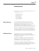
Chapter 1 Product Overview This chapter gives an overview of the Ethernet Network Interface. The following topics are covered: • • • • • • Ethernet Connection Ethernet Connection Non-Ethernet Devices Hardware Features Operating Modes Device Compatibility Ethernet Networks The 1761-NET-ENI provides Ethernet/IP connectivity for all MicroLogix controllers and other DF1 full-duplex devices.
1-2 Product Overview The ENI also supports an SMTP mail service that allows an existing controller to send e-mail messages to any destination connected to the network. The e-mail can be used to initiate the transmission of data or status information. Hardware Features Product Drawing RS-232 Mini-DIN Port Ethernet Port ENI ETHERNET INTERFACE MODULE CAT SER FRN 1761-NET-ENI A 1.01 WIN (21)1P6AA0BB Mfg. 1200 Fac. 1P R LISTED IND.CONT.EQ. FOR HAZ. LOC.
Product Overview 1-3 Default Settings The ENI’s RS-232 port has the following default settings: Table 1.1 RS-232 Settings Setting Default Other Options Baud Rate Autobaud see table 4.
1-4 Product Overview Operating Modes Messaging When the ENI is connected to a programmable controller (and connected to an Ethernet network), the controller can be accessed from other devices on Ethernet, or initiate communications to other Ethernet/IP devices. E-Mail The ENI also supports SMTP mail service, that allows a controller to send e-mail messages to any e-mail address on the network. The e-mail can be used to initiate the transmission of data or status information.
Product Overview Ethernet Networks 1-5 Basic Ethernet Topology The ENI Ethernet connector conforms to ISO/IEC 8802-3 STD 802.3 and utilizes 10Base-T media. Connections are made directly from the ENI to an Ethernet switch. The network setup is simple and cost effective. Typical network topology is pictured below.
1-6 Product Overview Publication 1761-UM006A-EN-P - February 2001
Chapter 2 Installation and Wiring This chapter covers installation and wiring for the ENI. It is divided into the following sections: • • • • • • • European Communities (EC) Directive Compliance European Communities (EC) Directive Compliance Safety Considerations Mounting External Power Supply Wiring ENI Port Identification Ethernet Connections RS-232 Port Connections This product has the CE mark. It is approved for installation within the European Union and EEA regions.
2-2 Installation and Wiring Tests. For specific information required by EN 61131-2, see the appropriate sections in this publication, as well as the Allen-Bradley publication Industrial Automation Wiring and Grounding Guidelines For Noise Immunity, publication 1770-4.1. Open style devices must be provided with environmental and safety protection by proper mounting in enclosures designed for specific application conditions.
Installation and Wiring Mounting 2-3 The 1761-NET-ENI must be mounted in the vertical position, as shown. Horizontal mounting is not recommended due to thermal considerations. Allow 50 mm (2 in.) of space on all sides for adequate ventilation. See page A-1 for operating temperature specification.
2-4 Installation and Wiring Removal DIN Side Rail View 1. Place a screwdriver in the DIN rail latch at the bottom of the unit. 2. Holding the unit, pry downward on the latch until the unit is released from the DIN rail. Panel Mounting Template See Appendix A for panel mounting template. Installation ATTENTION ! Mounting Template Be careful of metal chips when drilling mounting holes for your equipment within the enclosure or panel.
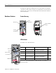
Installation and Wiring 2-5 ENI Port Identification ETHERNET RS232 FAULT NET TX/RX Ethernet Port (ENI Port 1) TX/RX RS-232 Mini-DIN (ENI Port 2) IP Write-on area for Ethernet IP address PWR CABLE EXTERNAL External Power Supply Wiring WARNING ! IMPORTANT 24 VDC DC NEUT CHS GND Bottom View EXPLOSION HAZARD - In Class I Division 2 applications, an external, Class 2 power supply must be used.
2-6 Installation and Wiring Ethernet Connections Ethernet 8-Pin 10Base-T Connector (Port 1) The Ethernet connector is an RJ45, 10Base-T connector. The pin-out for the connector is shown below: Pin Pin Name 1 Tx+ 2 Tx- 3 Rx+ 4 not used by 10Base-T 5 not used by 10Base-T 6 Rx- 7 not used by 10Base-T 8 not used by 10Base-T When to use straight-through and cross-over cable: • ENI Ethernet port to 10Base-T Ethernet switch cables utilize a straight-through pin-out (1-1, 2-2, 3-3, 6-6).
Installation and Wiring 2-7 Ethernet Cables Shielded and non-shielded twisted-pair 10Base-T cables with RJ45 connectors are supported. The maximum cable length between an ENI Ethernet port and a 10Base-T port on an Ethernet switch (without repeaters or fiber) is 100 meters (323 feet). However, in an industrial application, the cable length should be kept to a minimum.
2-8 Installation and Wiring RS-232 Port Connections RS-232 Connector 7 8 6 8-pin mini-DIN 3 5 4 2 1 Table 2.1 RS-232 Connector Pin Assignments Pin Port 2 1 24V dc 2 ground (GND) 3 no connection 4 ENI input data, RxD 5 no connection 6 no connection 7 ENI output data, TxD 8 ground (GND) RS-232 Cables Port 2 of the ENI is an 8-pin mini-DIN RS-232 port that provides connection to DF1 compatible RS-232 devices. The table below describes the RS-232 compatible cables.
Chapter 3 Operation This chapter describes ENI operation. The following information is included: • • • • Operation Overview Operation Overview Allocation of Ethernet Connections ENI Functional Overview Program Upload/Download and On-Line Sessions Ethernet is the protocol used to transport TCP/IP messages. On top of TCP, Ethernet/IP is the open protocol used by the ENI. Ethernet/IP allows devices to exchange information (data); or to upload, download, and edit logic programs over Ethernet.
3-2 Operation ENI Functional Overview The ENI provides Ethernet/IP connectivity for RS-232 devices that use DF1 full-duplex protocol. DF1 full-duplex is an open, point-to-point protocol used in any Allen-Bradley controller with an RS-232 port, and in many other devices. DF1 full-duplex supports up to 256 nodes. The ENI uses these nodes for different functions. The ENI uses a memory (node) map to provide access to the different functions you can perform.
Operation 3-3 2. The “Configure Dialog” will open, select Ethernet devices from the available drivers, and then click “OK” to load the driver into RSLinx. Once the Ethernet driver is loaded, either highlight and select “Configure” or simply double click on the Ethernet driver.
3-4 Operation At that point the station mapping screen will appear as illustrated here. Double click on the row below “Host Name”, and enter the TCP/IP addresses that match the devices on your network that you will need access to. When you are done entering the stations, click OK to close the station mapping window.
Operation 3-5 3. Open the AB_ETH-1 tree on your computer, autobrowse should be running and any active device that you have configured should be shown on the screen as illustrated below. RSLogix 500 1.
3-6 Operation 2. Select “AB_ETH-1, Ethernet. 3. Either expand the tree (select the + in the box, or select the device from the table to the right. From this point, you can then either go online or perform an upload or download.
Chapter 4 ENI Configuration (Node 248 to 254) This chapter describes configuration methods and parameters.
4-2 ENI Configuration (Node 248 to 254) COM Port Settings Use the Utility Settings screen to set the following: • COM Port - The PC’s RS-232 port that the communications cable is plugged into. • Baud Rate - Select a baud rate or choose Autobaud. See page 4-15 for more information. • Parameter Upload Behavior and Parameter Download Behavior - This setting controls which parameters will be saved or loaded when you use the Load From or Save To buttons.
ENI Configuration (Node 248 to 254) TIP 4-3 If you want to obtain the TCP/IP information via BOOTP, you must do that separately from the ENI Configuration Utility. See Appendix B. Save to ENI RAM or ENI ROM You must save the configurations you have set. Click ENI RAM for temporary setups or ENI ROM to permanently save your settings. If you do not save the settings, they will revert to “out-of-box” on the next power-up.
4-4 ENI Configuration (Node 248 to 254) Message Routing Use the Message Routing screen to fill in the destination addresses for DF1 messaging. Message routing is described in chapter 5. Reset Use the Reset screen to issue reset commands and to set the type of behavior that will occur at reset. The reset behavior options are described on page 4-11.
ENI Configuration (Node 248 to 254) Controller Messaging 4-5 When using this method, a write message is used to configure the TCP/IP configuration parameters. A CIF write message is initiated to the controller. CIF stands for Common Interface File and is supported by all Allen-Bradley programmable controllers that have an RS-232 port. The first item to configure is the ENI’s IP address on your network. See the following section, Configuring ENI Data Parameters, for that configuration procedure.
4-6 ENI Configuration (Node 248 to 254) Configuring ENI Data Parameters This example illustrates how to configure the ENI’s TCP/IP address (Node 250). TIP This procedure can also be used for any parameter that requires integer numbers (nodes 50 to 150, 250, 251, 252 and 253). 1. Create an integer data file. Inside the file arrange your TCP/IP data in groups of 4 words (as illustrated in file N50 below). 2. Create your message logic using whatever conditional instructions you may need.
ENI Configuration (Node 248 to 254) 4-7 3. Open the message instruction and enter the appropriate variables. The variables are described in Table 4.1. Table 4.
4-8 ENI Configuration (Node 248 to 254) Configuring ENI String Parameters Configuring the ENI E-Mail From String This example illustrates configuring the ENI E-mail From String (Node 249). To configure the E-mail From String, initiate a message with a string element as the data. EXAMPLE Node 249 - E-Mail From String Node 249 holds the ASCII string that will be sent with any e-mail message initiated by the ENI. To configure the E-mail From String, initiate a message with a string element as the data.
ENI Configuration (Node 248 to 254) 4-9 2. Create your message logic using whatever conditional instructions you may need. This example uses bit B3:0/7 to condition the MSG instruction and message file 10, element 16 to manage the message session. 3. Open the message instruction and enter the appropriate variables. The variables are described in Table 4.2. Table 4.
4-10 ENI Configuration (Node 248 to 254) ENI Configuration Parameters The following table shows the functions that nodes 248 to 255 perform and their default values. Descriptions of each function can be found following the table. Node Function Data Type Number of Elements Options Default 248 Save/Reset(1) Integer 1 0 = save configuration to flash n/a 1 = simple reset 2 = reset to factory defaults 3 = conditional reset 249 From String ASCII String 1 ENI Identifier ENI0.0.0.0@eni1761.
ENI Configuration (Node 248 to 254) 4-11 Node 248 - Save/Reset Function Depending on the value of the Save/Reset option, the ENI performs the following operations when receiving a PCCC Unprotected Write message of one element (integer) to Node 248. Value of Save/Reset ENI Operation 0 The ENI immediately stops all normal operations and saves the configuration to non-volatile memory. The ENI may take up to 60 seconds to complete IMPORTANT this save operation.
4-12 ENI Configuration (Node 248 to 254) Node 250 - TCP/IP Configuration This procedure describes configuration for the TCP/IP parameters. The TCP/IP parameters are configured by sending a message instruction to the ENI (or by using the ENI Configuration Utility). 1. Configure a 485CIF write message in the Allen-Bradley controller. IMPORTANT Only PLC2 type or 485CIF read/write messages can be used to configure the ENI. 2. Set the destination (target) node to 250.
ENI Configuration (Node 248 to 254) 4-13 Subnet Mask A subnet mask is used to interpret IP addresses when the network is divided into subnets. If your network is not divided into subnets, then leave the subnet mask at the default or allow the ENI Configuration Utility to assign a default. The subnet mask defaults to auto-detect mode “out-of-box”. As long as the subnet mask is not manually set, the auto-detect mode follows the rules as shown below: Table 4.
4-14 ENI Configuration (Node 248 to 254) The security masks default value is 0.0.0.0 out-of-box, which is defined as “accept all register session requests”. A Security Mask of 255.255.255.255 is also defined as “accept all register session requests”. TIP The security mask acts as a filter on the source IP address such that any mask octet set to the value of 255 becomes “don’t care” octets in the source IP address and all other fields must match exactly.
ENI Configuration (Node 248 to 254) 4-15 Node 251 - E-Mail Server The TCP/IP address stored in this location defines the mail server. The ENI sends all e-mail requests to this server, which then sends the e-mail message to the destination. Node 252 - BOOTP Configuration The ENI allows the BOOTP request to be disabled by clearing the BOOTP Enable parameter in the channel Configuration File.
4-16 ENI Configuration (Node 248 to 254) Table 4.7 ENI Baud Rate Options Configuration Value (Integer) Baud Rate 0x0000 Autobaud Enabled 0x0001 1200 0x0002 2400 0x0003 4800 0x0004 9600 0x0005 19.2K 0x0006 38.4K(1) 0x0007 57.6K(1) 8 to 65535 Autobaud Enabled (1) All CompactLogix devices must be configured to use two stop bits when communicating with the ENI at 38.4K. IMPORTANT The ENI cannot Autobaud to 57.6K to synchronize to the attached controller.
Chapter 5 Peer-to-Peer Messaging This chapter describes messaging between the ENI and DF1 devices. The following topics are covered: • Messaging Between the ENI and DF1 Devices • Message to Configuration Nodes (Nodes 100 to 149) • Sending a Message to a Destination Controller (Nodes 0 to 49) Messaging Between the ENI and DF1 Devices The ENI can route a DF1 message received from the attached controller to a compatible destination TCP/IP device.
5-2 Peer-to-Peer Messaging The table below illustrates the relationship between messages and their corresponding configuration addresses. Table 5.1 Message Routing ENI receives read or write PCCC message to ENI TCP/IP route Message forwarded to destination configuration node TCP/IP address Node 0 Node100 111.222.233.200 (stored at Node 100) Node 1 Node101 111.222.233.
Peer-to-Peer Messaging Message to Configuration Nodes (Nodes 100 to 149) 5-3 When the ENI receives a message to Node Address 0 to 49, it looks up the TCP/IP address associated with the address at Nodes 100 to 149. The ENI preserves the original DF1 address when sending back a reply. The following table illustrates the relationship between configuration addresses and their corresponding messaging address. Table 5.
5-4 Peer-to-Peer Messaging Sending a Message to a Destination Controller (Nodes 0 to 49) The ENI uses a pair of node addresses to send data messages over TCP/IP. For data, two sets of addresses are used as illustrated in the table below. Node numbers 100 to 149 are used to define or store the actual TCP/IP address, and nodes 0 to 49 are used to send the data to the destination. Table 5.
Peer-to-Peer Messaging 5-5 Open the message instruction and enter the appropriate variables. The variables are described in Table 5.4. Table 5.4 Message Instruction Variables for Sending a Message to a Destination Controller Variable Setting This Controller Parameters: Communication Command Use any command supported by your controller. Data Table Address Use any valid file. Size in Elements For all ENI data configuration, always set this to 4 (4 words).
5-6 Peer-to-Peer Messaging Publication 1761-UM006A-EN-P - February 2001
Chapter 6 E-Mail Messages (Node 50 to 99) This chapter describes using the ENI’s e-mail feature. The following topics are included: • Overview • Configuring E-Mail • Sending an E-Mail Message Overview The ENI is capable of transmitting e-mail messages generated by the attached controller. This provides an extremely versatile mechanism to report alarms, status, and other data-related functions.
6-2 E-Mail Messages (Node 50 to 99) Configuring E-Mail SMTP E-Mail Address To configure the e-mail function, two parameters must be configured: • SMTP mail server IP address - configured by sending a write message to node 251 (e-mail server). See page 4-15 for more information. IMPORTANT The ENI only accepts the configuration in the form of 4 elements (words) from an Integer file. • A “From” String - configure by sending a write message to node 249 (from string).
E-Mail Messages (Node 50 to 99) 6-3 Destination Addresses The ENI stores e-mail addresses; it does not store the e-mail messages. To store a destination address, write a message to a specific node number (nodes 150 to 199). The message data must be a string element that contains a valid e-mail ASCII text string address, as illustrated in ST15:0 through ST15:5 in the example below. IMPORTANT Remember the following when setting up destination addresses: • The ENI can store up to 50 e-mail addresses.
6-4 E-Mail Messages (Node 50 to 99) E-Mail Message E-Mail Address Configuration Description Node 50 Node 150 The data within the message is sent to Node 50 and forwarded to the e-mail address stored at Node 150. Node 51 Node 151 The data within the message is sent to Node 51 and forwarded to the e-mail address stored at Node 151. Node 52 Node 152 The data within the message is sent to Node 52 and forwarded to the e-mail address stored at Node 152.
E-Mail Messages (Node 50 to 99) Sending an E-Mail Message 6-5 The ENI uses a pair of node addresses to send e-mail or data messages over TCP/IP. To send e-mail, two sets of addresses are used as illustrated in the table below. Node numbers 150 to 199 are used to define or store the actual e-mail address, and nodes 50 to 99 are used to send the string element to the e-mail recipient.
6-6 E-Mail Messages (Node 50 to 99) 2. Open the message instruction and enter the appropriate variables. The variables are described in Table 6.1. Table 6.1 Message Instruction Variables for Sending an E-Mail Message Variable Setting This Controller Parameters: Communication Command Use any command supported by your controller. Data Table Address Any valid string, such as ST25:21 as shown below.
Chapter 7 Connecting 1769-L20 CompactLogix Controllers on Ethernet The chapter contains an example of using the ENI on an Ethernet network. It is arranged as follows: • • • • • • • • • System Diagram System Diagram Purpose Scope General Ethernet Information Configuring 1761-NET-ENI #1 Configuring 1761-NET-ENI #2 Configure RSLINX and Download The Program To The 1769-L20 Create MSG Programs for the SLC 5/05 and the 5550 Controllers Configuring an Ethernet Driver in RSLINX Figure 7.
7-2 Connecting 1769-L20 CompactLogix Controllers on Ethernet The computer must include the following software: • • • • RSLOGIX5000, version 7.00 or later RSLINX, version 2.30.00 or later RSLOGIX500 ENI Configuration Tool The 1769-L20 controller must contain firmware 7.17 or later. The Ethernet Interface Card in the computer is used to connect directly to the SLC 5/05 controller (channel 1) and to the 5550 controller via the 1756-ENET card.
Connecting 1769-L20 CompactLogix Controllers on Ethernet General Ethernet Information 7-3 Each Ethernet device requires a unique IP address. If your Ethernet network is isolated from the company-wide network, any valid IP addresses may be used. If your Ethernet hub is connected to a larger Ethernet network, contact your System Administrator for unique IP addresses. For this example, the following IP addresses will be assigned to the various Ethernet devices on our network: Table 7.
7-4 Connecting 1769-L20 CompactLogix Controllers on Ethernet Figure 7.2 Throttling Message Instructions Configuring 1761-NET-ENI #1 Refer to Chapter 4 of this manual for information on how to obtain the free ENI Configuration Software Tool. The first task is to configure the ENI module that will be connected to the computer. This is ENI #1 per Figure 7.1. A 1761-CBL-PMO2 serial cable is used to connect a computer serial communication port to the RS-232 mini-din serial port on the ENI.
Connecting 1769-L20 CompactLogix Controllers on Ethernet 7-5 For this example, we will be using 38400 baud on all serial connections. We will also assign IP addresses to all Ethernet products rather than using BOOTP. Two tabs in the ENI software tool must be modified for the purposes of this example, the “ENI IP Addr” tab and the “Message Routing” tab. The IP address for the ENI connected to the 1769-L20 controller (ENI #2) is the only address we need to add to the ENI #1 Message Routing table.
7-6 Connecting 1769-L20 CompactLogix Controllers on Ethernet Then, connect the serial cable between your computer and ENI #1 and click on the ENI IP Addr tab. From this tab, under the “Save To” column, click the ENI ROM button. This will download your configuration parameters to ENI #1 and save it to non-volatile memory. Configuring 1761-NET-ENI #2 ENI #2 is connected to the L20 controller. This ENI must be configured with its own IP address (131.200.50.
Connecting 1769-L20 CompactLogix Controllers on Ethernet 7-7 Figure 7.7 ENI #2 Configuration - RSLogix 5000 Ladder Program The above ladder rungs, 2 through 7 and the rungs, 0 and 1 shown earlier in this application example, make up the ladder program for the L20 controller. Details of each MSG Instruction will follow. In the above program, Rung 2 initiates the string of configuration messages with input instruction “Reconfig_ENI”.
7-8 Connecting 1769-L20 CompactLogix Controllers on Ethernet The 5 rungs used to configure ENI #2 are defined as follows: Table 7.3 ENI #2 Configuration - Rung Descriptions Rung Function Rung 2 This rung initiates the process and configures the ENI module’s Serial port for 38400 Baud. Rung 3 This rung is initiated by the Done bit of the previous MSG and it disables BOOTP. Rung 4 This rung configures the ENI with its own IP address.
Connecting 1769-L20 CompactLogix Controllers on Ethernet 7-9 For this example, as mentioned earlier, we will assign the following IP addresses to the devices on Ethernet: Table 7.5 Example IP Addresses for Ethernet Devices Device Node Address (for L20 MSG) IP Address SLC-5/05 1 131.200.50.92 1756-ENET 45 131.200.50.93 1761-NET-ENI #2 N/A 131.200.50.94 1761-NET-ENI #1 N/A 131.200.50.95 Computer Ethernet Card N/A 131.200.50.
7-10 Connecting 1769-L20 CompactLogix Controllers on Ethernet Figure 7.8 ENI #2 Configuration - Message Configuration Tab Figure 7.9 ENI #2 Configuration - Message Communication Tab Note that the MSG length is 8 bytes or 4 integer words. These 4 words contain the IP address for ENI #2 and are stored in tag ENI_IP_VALUE, which is a tag address containing 4 integer words.
Connecting 1769-L20 CompactLogix Controllers on Ethernet 7-11 the L20 controller’s tag database shown below. On the MSG Instruction’s Communication tab above, the path is “2,250”, where the 2 represents the L20 controllers serial port and the 250 tells the ENI module that the 4 words of data contain its IP address. Figure 7.10 L20 Controller’s Tags Per Table 7.4, The MSGs in Rungs 2, 3 and 7 are 2 bytes or 1 integer word in length.
7-12 Connecting 1769-L20 CompactLogix Controllers on Ethernet Enter your 1769-L20 ladder program per Rungs 0 through 7 as shown and described above. Be sure to enter your IP addresses for ENI #2, the SLC 5/05, and the 1756-ENET into the proper tags in the controller’s tag database. Before saving your program, enter the Controller Properties window by clicking on the Edit pull-down menu and select Controller Properties.
Connecting 1769-L20 CompactLogix Controllers on Ethernet 7-13 In the File Number column enter 12. Under the Tag Name, click on the right side in the white box to reveal your Controller Tags and select the tag name you created for this purpose (“Data_From_505” for this example). More than one entry may be mapped. When finished, your Map PLC/SLC screen for the L20 controller should look like the following: Figure 7.12 File Mapping for the L20 Controller in RSLogix 5000 Save your program.
7-14 Connecting 1769-L20 CompactLogix Controllers on Ethernet Figure 7.13 Modify DF1 Parameters Using RSLInx It is very important that the “Station Number” match the “Destn” number in ENI #1, assigned to the IP address for ENI #2. In this example, we arbitrarily used Destn address 2 to represent IP address 131.200.50.94, which is the IP address of ENI #2. DO NOT click on the “Auto Configure” button on this screen. When you have properly modified the parameters on this screen, click OK.
Connecting 1769-L20 CompactLogix Controllers on Ethernet Create MSG Programs for the SLC 5/05 and the 5550 Controllers 7-15 We must now create MSG ladder programs for our other two controllers on Ethernet. The following is the MSG ladder program for the SLC 5/05 controller, developed with RSLOGIX500. Following the ladder program are four additional screens showing the two tabs for each MSG Instruction.
7-16 Connecting 1769-L20 CompactLogix Controllers on Ethernet Figure 7.15 SLC 5/05 Rung 0 MSG “General” Tab Figure 7.
Connecting 1769-L20 CompactLogix Controllers on Ethernet 7-17 Figure 7.17 SLC 5/05 Rung 1 MSG “General” Tab Figure 7.
7-18 Connecting 1769-L20 CompactLogix Controllers on Ethernet The following is the MSG ladder program for the 5550 controller, developed with RSLOGIX5000. Following the ladder program are four additional screens showing the two tabs for each MSG Instruction. As part of your program, you must configure your 1756-ENET module with the proper IP address. Figure 7.
Connecting 1769-L20 CompactLogix Controllers on Ethernet 7-19 Figure 7.20 ControlLogix 5550 Rung 0 Message Configuration Tab Figure 7.
7-20 Connecting 1769-L20 CompactLogix Controllers on Ethernet Figure 7.22 ControlLogix 5550 Rung 1 Message Configuration Tab Figure 7.23 ControlLogix 5550 Rung 1 Message Communication Tab The 1761-NET-ENI modules do not support CIP commands. Therefore, all commands between controllers used in this application example are PLC_5 Typed Write commands. These commands require a PLC-5 type address to send the data to the receiving controller.
Connecting 1769-L20 CompactLogix Controllers on Ethernet 7-21 addresses do not exist in Logix controllers, so they must be mapped to existing tags in these controllers. From the Logic pull down menu, select “Map PLC/SLC Messages”. Your mapped table for your 5550 program should look like the following: Figure 7.24 File Mapping for the ControlLogix 5550 Controller in RSLogix 5000 Save your program.
7-22 Connecting 1769-L20 CompactLogix Controllers on Ethernet Figure 7.25 Configure Ethernet Driver Using RSLinx From the RSLOGIX500 programming software, you should now be able to download your SLC 5/05 program. Then, from the RSLOGIX5000 software you should now be able to download your 5550 controller program. Once all programs are downloaded to their respective controllers, place each controller into the RUN mode and a MSG from each controller will be sent to each of the other controllers.
Chapter 8 Troubleshooting This chapter covers the following Troubleshooting topics: • • • • • Network Troubleshooting Network Troubleshooting LED Sequence at Power-Up Troubleshooting Using the LED Indicators Error Codes Generated by the ENI Message Instruction Error Codes Maintain ENI Connections The UTP (unshielded twisted pair) patch cable on a switch should be labeled and treated as dedicated. Be careful when moving any cables, as port identity may be effected.
8-2 Troubleshooting Troubleshooting Using the LED Indicators The ENI status LEDs provide a mechanism to determine the current status of the ENI if a programming device is not present or available. The LED behavior is described in the following table.
Troubleshooting Error Codes Generated by the ENI This table shows the error codes that may be generated by the ENI. A full listing of error codes that may be generated by the Message Instruction is shown below. Error Code Description of Error Condition 10H Target node cannot respond because of incorrect command parameters or unsupported command. Possible causes: • The data size of the message is invalid. • The data format is incorrect for any of the supported PCCC messages.
8-4 Troubleshooting Error Code Description of Error Condition 15H Local channel configuration parameter error exists. 16H Target or Local Bridge address is higher than the maximum node address. 17H Local service is not supported. 18H Broadcast is not supported. 21H Bad MSG file parameter for building message. 30H PCCC Description: Remote station host is not there, disconnected, or shutdown. 37H Message timed out in local processor.
Troubleshooting 8-5 Error Code Description of Error Condition E6H PCCC Description: Illegal Address, address does not exist, or does not point to something usable by this command. E7H Target node cannot respond because length requested is too large. E8H PCCC Description: Cannot complete request, situation changed (file size, for example) during multi–packet operation. E9H PCCC Description: Data or file is too large. Memory unavailable.
8-6 Troubleshooting Publication 1761-UM006A-EN-P - February 2001
Appendix A Specifications Physical Specifications Description 24V dc Power Source Requirement 24V dc Current Draw Maximum Inrush Current Internal Isolation Vibration Shock Operating Ambient Temperature Storage Temperature Humidity Agency Certification Radiated and Conducted Emissions: • ESD Immunity (EN 1000-4-2) • Radiated Immunity (EN 1000-4-3) • Fast Transient Burst (EN 1000-4-4) • Surge Immunity (EN 1000-4-5) • Conducted Immunity (EN 1000-4-6) Ethernet Specifications ENI Specification 20.4 to 26.
A-2 Specifications Dimensions Product Dimensions 52.07 mm (2.05 in.) 118 mm (4.64 in.) 107 mm (4.20 in.) Mounting Dimensions 52.07 mm (2.05 in) 27.7 mm (1.09 in.) Allow 15 mm (0.6 in.) clearance for DIN rail latch movement during installation and removal. 118 mm (4.64 in) 107 mm (4.20 in) 27.7 mm (1.09 in) Publication 1761-UM006A-EN-P - February 2001 Allow 15 mm (0.6 in.) clearance for DIN rail latch movement during installation and removal. 64.8 mm (2.55 in.
Appendix B BOOTP Configuration Method (default) BOOTP (Bootstrap protocol) is a low-level protocol that provides configuration information to other nodes on a TCP/IP network with DOS, Microsoft Windows, Windows NT, Windows 9x, VMS, and HP-UNIX platforms. BOOTP configuration files let you automatically assign IP addresses to the ENI. You can also set Subnet Masks and Gateway addresses using BOOTP. To use BOOTP, a BOOTP Server must exist on the local Ethernet Subnet.
B-2 BOOTP Configuration Method (default) When BOOTP is enabled, the following events occur at power-up: • The ENI broadcasts a BOOTP-request message containing its hardware address over the local network or subnet. • The BOOTP server compares the hardware address with the addresses in its look-up table in the BOOTPTAB file. • The BOOTP server sends a message back to the ENI with the IP address and other network information that corresponds to the hardware address it received.
BOOTP Configuration Method (default) B-3 Edit the BOOTP Configuration File The boot-server configuration file, BOOTPTAB, is located in the C:\ABIC\BIN directory.
B-4 BOOTP Configuration Method (default) 2. Make one copy of the configuration template for each ENI in your system. 3. Edit each copy of the template as follows: a. Replace “sigma1” with the name of the ENI. Use only letters and numbers; do not use underscores. b. Replace “12.34.56.1” with the IP address to be assigned to the ENI. c. Replace “ha=0000BC1D1234” with the ENI’s hardware address. Use only hexadecimal digits (0-9, A-F); do not use the hyphens that separate the numbers. 4.
BOOTP Configuration Method (default) B-5 Based on this configuration, the BOOTPTAB file looks like: #Legend:gw -- gateways #ha -- hardware address #ht -- hardware type (1) #ip -- host IP address #sm -- subnet mask #vm -- BOOTP vendor extensions format (2) #tc -- template host #Default string for each type of Ethernet client defaults5E: ht=1:vm=rfc1048 #Entries for SLC 5/05 processors: sigma1: tc=defaults5E:ip=12.34.56.1:ha=0000BC1D1234 sigma2: tc=defaults5E:ip=12.34.56.
B-6 BOOTP Configuration Method (default) Running the DOS-Based Utility To run the boot-server utility, DTLBOOTD.EXE, follow these steps: 1. At the DOS prompt, type: DTLBOOTD [-D] [-T ] [-B ] [-F ] [configfile] [logfile] Parameter Description -D provide additional information for debug purposes. -T exit after seconds of inactivity. -B exit after answering number of boot requests.
Glossary ASA (Advanced System Architecture) Autobaud A feature that allows a communications port to automatically synchronize to the device or network that it is attached to. This feature typically minimizes the amount of configuration required, and also makes is easier to replace devices. Auto BCC/CRC Sends a test message during autobaud to detect which Error Detecting setting to use, BCC or CRC. This will not occur for fixed baud rate settings. The ENI uses CRC for fixed baud rates.
Glossary 2 Full-duplex A high-performance protocol that allows simultaneous two-way data transmission. For point-to-point applications only. IP (Internet Protocol) IP specifies the format of packets and the addressing scheme. Most networks combine IP with a higher-level protocol called Transport Control Protocol (TCP), which establishes a virtual connection between a destination and a source. IP by itself is something like the postal system.
Glossary 3 PCCC (Programmable Controller Communications Commands) RS-232 An EIA standard that specifies electrical, mechanical, and functional characteristics for serial binary communication circuits. Security Mask The Security Mask, when configured, allows you to restrict incoming TCP/IP and/or UDP messages to have source IP addresses that are within some prescribed range.
Glossary 4 UTP (Unshielded Twisted Pair) The type of cable used in 10BaseT systems.
Index A Allen-Bradley contacting for assistance P-3 support P-3 ASA definition G-1 Auto BCC/CRC definition G-1 Autobaud definition G-1 restrictions 4-16 B Baud Rate configuring 4-15 definition G-1 BOOTP edit configuration file B-3 example B-4 IP address B-4 BOOTP Configuration 4-15, B-1 Boot-Server Host B-2 C Cables 2-2, 2-6, 2-7, 2-8 CE Mark 2-1 CIP definition G-1 Common Techniques Used in this Manual P-2 Compatibility 1-4 Configuration 4-1 BOOTP 4-15 controller messaging 4-5 e-mail 6-2 list of parameter
2 Index F Fault LED 1-2 From String 4-11, 6-2 Full-Duplex definition G-2 G Grounding 2-5 H Hardware Address 1-2, 4-16 Hardware Features 1-2 Hazardous Location 2-2 I Installation and Wiring 2-1 Integer Files 4-6 IP definition G-2 IP Address assigning 1-5 definition G-2 ENI write-on area 1-2 L LED Indicators 1-2 LED Sequence at Power-Up 8-1 LInk LED 1-2 Low Voltage Directive 2-1 M Manuals, Related P-2 Memory Map 3-2 Messaging 4-5, 5-1 Mounting 2-3 dimensions A-2 Publication 1761-UM006A-EN-P - February
Index S Safety Considerations 2-2 Save/Reset 4-11 Security Mask 4-13 definition G-3 Single-Hop definition G-3 SMTP definition G-3 SMTP E-Mail Address 6-2 Specifications A-1 String Files 4-8 Subnet Mask 4-13 3 T TCP definition G-3 TCP/IP configuration 4-12 definition G-3 Troubleshooting contacting Allen-Bradley for assistance P-3 maintain ENI connnections 2-7 procedure 8-1 TX/RX LED 1-2 U UCMM definition G-3 Upload/Download 3-2 UTP definition G-4 W Web Browser 1-5 Wiring 2-1 Publication 1761-UM006A-EN-
4 Index Publication 1761-UM006A-EN-P - February 2001
Publication 1761-UM006A-EN-P - February 2001 2 Supersedes Publication XXXX-X.X.X - Month Year PN XXXXXX-XX © 2001 Rockwell International Corporation. Printed in the U.S.A.