Maintenance & Service Guide HP 205 G1 All-in-One Business PC HP 18 All-in-One Business PC
© Copyright 2013, 2014 Hewlett-Packard Development Company, L.P. The information contained herein is subject to change without notice. Microsoft and Windows are U.S. registered trademarks of the Microsoft group of companies. The only warranties for HP products and services are set forth in the express warranty statements accompanying such products and services. Nothing herein should be construed as constituting an additional warranty.
About This Book WARNING! Text set off in this manner indicates that failure to follow directions could result in bodily harm or loss of life. CAUTION: Text set off in this manner indicates that failure to follow directions could result in damage to equipment or loss of information. NOTE: Text set off in this manner provides important supplemental information.
iv About This Book
Table of contents 1 Product Features ........................................................................................................................................... 1 Overview ................................................................................................................................................................ 1 Front components ................................................................................................................................................
Cleaning the keyboard ...................................................................................................................... 15 Cleaning the display .......................................................................................................................... 16 Cleaning the mouse ........................................................................................................................... 16 Service considerations ....................................................
Troubleshooting Without Diagnostics ........................................................................................................... 62 Safety and Comfort ............................................................................................................................................. 62 Before You Call for Technical Support ................................................................................................................ 62 Helpful Hints ...............................
11 Password Security and Resetting CMOS ..................................................................................................... 109 Establishing a Setup or Power-on password .................................................................................................... 109 Resetting the Setup and Power-on password .................................................................................................. 110 Clearing and resetting the CMOS ..........................................
1 Product Features Overview The HP All-in-One Business PC offers the following features: ● Integrated All-in-One form factor ● 18.
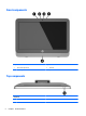
Front components Component Component 1 Internal microphones (2) 3 Webcam 2 Webcam light 4 Speaker Top components Component 5 2 Power button Chapter 1 Product Features
Right components Component 6 Optical drive Right components 3
Left components 4 Component Component 7 Drive light 10 Audio-in (microphone) jack 8 Memory card reader 11 Audio-out (headphone) jack 9 USB 3.
Rear components Component Component 12 Power connector 14 USB ports (4) 13 RJ-45 (network) jack 15 Audio line-out jack Rear components 5
2 Activating and Customizing the Software Activating and customizing the software in Windows 8 Additional information is available in online help after you activate the operating system. NOTE: Be sure there is a 10.2 cm (4 inch) clearance at the back of the unit and above the monitor to permit the required airflow. Activating the Windows Operating System The first time you turn on the computer, the operating system is set up and activated automatically. This process takes about 5 to 10 minutes.
3 Illustrated parts catalog Boards and memory Item Component (1) System board (includes processor and replacement thermal material): Spare part number For use in HP 205 G1 models: ● AMD E1-2500 APU for use in models without Windows 8.1 751275-001 ● AMD E1-2500 APU for use in models with Windows 8.1 Standard 751275-501 ● AMD E1-2500 APU for use in models with Windows 8.1 Professional 751275-601 For use in HP 18 models: ● Intel Pentium J2900 processor for use in models without Windows 8.
Item Component Spare part number 4-GB 689373-001 2-GB 689372-001 Miscellaneous parts Item Component Spare part number (1) Speakers 752343-001 (2) Hard drive screw bumpers 752334-001 (3) Fan 752335-001 (4) Front bezel 752331-001 Rear cover 752332-001 Display panel, 18.
Mass storage devices Item Spare part number Hard drives 2-TB, 7200 rpm 616608-001 750-MB, 7200 rpm 639363-001 500-MB, 7200 rpm 636929-001 Optical drive DVD±RW drive 657958-001 Cables Component Spare part number Backlight cable 752330-001 Power button board cable 752336-001 Webcam cable 752337-001 Hard drive cable assembly 752338-001 Optical drive cable assembly 752339-001 LVDS (display) cable 752340-001 Converter board cable 752341-001 Sequential part number listing Spare part numb
10 Spare part number Description 729339-001 Keyboard, USB, unbranded, United States 729339-AA1 Keyboard, USB, unbranded, Chinese 751275-001 System board for use in HP 205 G1 models (includes AMD E1-2500 APU) without Windows 8 (includes replacement thermal material) 751275-501 System board for use in HP 205 G1 models (includes AMD E1-2500 APU) with Windows 8 Standard (includes replacement thermal material) 751275-601 System board for use in HP 205 G1 models (includes AMD E1-2500 APU) with Windows
4 Serial ATA (SATA) drive guidelines and routine care and disassembly preparation This chapter provides general service information for the computer. Adherence to the procedures and precautions described in this chapter is essential for proper service. CAUTION: When the computer is plugged into an AC power source, voltage is always applied to the system board. You must disconnect the power cord from the power source before opening the computer to prevent system board or component damage.
SMART ATA drives The Self Monitoring Analysis and Recording Technology (SMART) ATA drives for the HP Personal Computers have built-in drive failure prediction that warns the user or network administrator of an impending failure or crash of the hard drive. The SMART drive tracks fault prediction and failure indication parameters such as reallocated sector count, spin retry count, and calibration retry count. If the drive determines that a failure is imminent, it generates a fault alert.
● To avoid hand contact, transport products in static-safe containers such as tubes, bags, or boxes. ● Protect all electrostatic parts and assemblies with conductive or approved containers or packaging. ● Keep electrostatic sensitive parts in their containers until they arrive at static-free stations. ● Place items on a grounded surface before removing them from their container. ● Always be properly grounded when touching a sensitive component or assembly.
Recommended materials and equipment Materials and equipment that are recommended for use in preventing static electricity include: ● Antistatic tape ● Antistatic smocks, aprons, or sleeve protectors ● Conductive bins and other assembly or soldering aids ● Conductive foam ● Conductive tabletop workstations with ground cord of one-megohm +/- 10% resistance ● Static-dissipative table or floor mats with hard tie to ground ● Field service kits ● Static awareness labels ● Wrist straps and footwea
Routine care General cleaning safety precautions 1. Never use solvents or flammable solutions to clean the computer. 2. Never immerse any parts in water or cleaning solutions; apply any liquids to a clean cloth and then use the cloth on the component. 3. Always unplug the computer when cleaning with liquids or damp cloths. 4. Always unplug the computer before cleaning the keyboard, mouse, or air vents. 5. Disconnect the keyboard before cleaning it. 6.
CAUTION: Never remove a wide leveled key (like the space bar) from the keyboard. If these keys are improperly removed or installed, the keyboard may not function properly. ● Cleaning under a key may be done with a swab moistened with isopropyl alcohol and squeezed out. Be careful not to wipe away lubricants necessary for proper key functions. Use tweezers to remove any fibers or dirt in confined areas. Allow the parts to air dry before reassembly.
Cables and connectors Most cables used throughout the unit are flat, flexible cables. These cables must be handled with care to avoid damage. Apply only the tension required to seat or unseat the cables during insertion or removal from the connector. Handle cables by the connector whenever possible. In all cases, avoid bending or twisting the cables, and ensure that the cables are routed in such a way that they cannot be caught or snagged by parts being removed or replaced.
5 Removal and Replacement Procedures Allin One (AIO) Chassis The following sections provide information about disassembling various components of the computer. Preparing to disassemble the computer To avoid injury and equipment damage, always complete the following steps in order, when opening the HP Pro All-in-One. 1. Remove all media from the computer. 2. Shut down the computer. 3. After the system has completely shut down, disconnect the power adapter from the back of the computer. 4.
Rear cover Description Spare part number Rear cover 752332-001 The computer has one main rear cover that allows access to internal components. To remove the rear cover: 1. Prepare the computer for disassembly (see Preparing to disassemble the computer on page 18). 2. On the bottom of the computer, turn the two captive screws (1) to the left until they click and release the rear cover. 3. Lift up on the bottom of the rear cover to disengage it (2), and then lift the rear cover off the computer (3).
Stand assembly Description Spare part number Stand assembly 752333-001 The stand is secured with four Torx screws. You must remove the rear cover to remove the stand. To remove the stand: 1. Prepare the computer for disassembly (see Preparing to disassemble the computer on page 18). 2. Remove the rear cover (see Rear cover on page 19). 3. On the side of the rear cover, in the order stamped into the stand, remove the four Torx screws that secure the stand to the rear cover (1). 4.
Webcam module Description Spare part number Webcam module 752344-001 On products that ship with a webcam module, the module is located at the top of the computer beneath the top panel. It is secured with two silver Phillips screws and has one connector. The webcam module is optional. To remove the webcam module: 1. Prepare the computer for disassembly (see Preparing to disassemble the computer on page 18). 2. Remove the rear cover (see Rear cover on page 19). 3.
To install a webcam module, reverse the removal procedures. Replacing drives Replacing the hard disc drive with a 3.5-inch drive or a 2.5-inch drive Description Spare part number 2-TB, 7200 rpm hard drive 616608-001 750-GB, 7200 rpm hard drive 639363-001 500-GB, 7200 rpm hard drive 636929-001 Hard drive screw bumper 752334-001 The hard disc drive is located on the left side of the computer (when viewed from behind). The drive is housed in a removable cage. To install a 2.
3. Loosen the captive Phillips screw (1) that secures the hard drive cage to the computer, and then slide the cage toward the edge of the chassis to disengage it from the connector, and lift it out of the computer (2). NOTE: Hard drive cage appearance may vary. 4. Both 3.5-inch and 2.5-inch hard drives are supported. A 2.5-inch hard drive requires an adapter to fit into the hard drive cage. To remove the hard drive, refer to the procedures below that correspond to the size of your drive: 3.
2.5-inch hard drive: a. Remove the four Phillips screws (1) that secure the drive adapter to the cage, and then slide the drive out of the cage (2). b. Remove the four Phillips screws that secure the drive to the adapter (1), and the slide the drive out of the adapter (2). To replace the hard drive, reverse the removal procedures. NOTE: To install an optional 2.5-inch drive, you must 1. Mount the drive in a drive adapter 2.
Replacing the optical disc drive Description Spare part number DVD±RW drive 657958-001 The optical disc drive is located above the hard disc drive on the left side of the computer (when viewed from behind). The optical drive data cable connects to the SATA1 and SATA PWR1 system board connectors. NOTE: The drive bracket is not spared. When replacing an optical drive, remove the bracket from the old drive and install it on the new drive. 1.
4. Remove the two screws securing the optical disc drive bracket to the drive, and then remove the bracket. To replace the optical drive, reverse the removal procedures.
Front bezel Description Spare part number Front bezel 752331-001 The front bezel is secured to the main system bracket with seven Torx screws. To remove the front bezel: 1. Prepare the computer for disassembly (see Preparing to disassemble the computer on page 18). 2. Remove the rear cover (see Rear cover on page 19). 3. Remove the speakers (see Speakers on page 33). 4. Remove the webcam (see Webcam module on page 21). 5. Disconnect the power button board cable. 6.
7. Disengage the nine tabs that secure the bezel to the computer (pointed out with white circles in the following illustration). NOTE: Although the following image shows the computer with most components removed, you can remove the bezel with all components installed except for the speakers. 8. Lift the computer from the bezel. To install the front bezel, reverse the removal procedures.
Converter board Description Spare part number Converter board 751276-001 The converter board is located on the left side of the computer (viewed from behind) under the main rear cover. It is secured with two Torx screws and has two connectors. Use the same converter spare part for all display panels; however, you must change jumper settings on the board based on the display panel. To remove the converter board: 1.
5. Lift the converter board from the computer (3). To install the converter board, reverse the removal procedures.
Power button board Description Spare part number Power button board 752342-001 The power button board is located on the top left of the computer (when viewed from behind). To remove the power button board: 1. Prepare the computer for disassembly (see Preparing to disassemble the computer on page 18). 2. Remove the rear cover (see Rear cover on page 19). 3. Remove the Torx screw that secures the bracket to the computer (1), and then lift the bracket off the computer (2). 4.
5. Press on the tab that holds the power button board in place (2), and the remove the board from the computer. To install the power button board, reverse the removal procedures.
Speakers Description Spare part number Speakers 752343-001 The speakers are located at the bottom of the computer. Two separate speakers are each secured by two Torx screws. To remove the speakers: 1. Prepare the computer for disassembly (see Preparing to disassemble the computer on page 18). 2. Remove the rear cover (see Rear cover on page 19). 3. Remove two Torx screws (1) that secure each speaker to the computer. 4.
Fan Description Spare part number Fan 752335-001 The fan is located near the middle of the computer and is secured with three Torx screws. You have to remove the metal plate to remove the fan. To remove the fan assembly: 34 1. Prepare the computer for disassembly (see Preparing to disassemble the computer on page 18). 2. Remove the rear cover (see Rear cover on page 19). 3. Remove the two Torx screws that secure the bracket to the computer (1), and then lift the bracket off the computer (2). 4.
6. Disconnect the fan cable from the system board connector labeled CHFAN2 (3). 7. Remove the fan from the computer. To install the fan assembly, reverse the removal procedures.
Hard drive and optical drive cables and connectors Description Spare part number Optical drive cable 752339-001 Hard drive cable 752338-001 The hard drive and optical drive connectors are located near the middle of the computer. Each connector is secured with two Torx screws and has two cables that connect to the system board. The optical drive connector cables are longer than the hard drive connector cables. To remove the hard drive or optical drive connector: 1.
8. Remove the connector from the computer. To install the hard drive or optical drive connector, reverse the removal procedures.
System board cover To remove the system board cover: 38 1. Prepare the computer for disassembly (see Preparing to disassemble the computer on page 18). 2. Remove the rear cover (see Rear cover on page 19). 3. Remove the four Torx screws that secure the cover to the computer.
4. Lift the cover straight up and off the computer. To replace the lower panel, reverse the removal procedures.
Memory Description Spare part number 4-GB memory module (PC3-12800; SODOMM) 689373-001 2-GB memory module (PC3-12800; SODOMM) 689372-001 Memory modules are located on the right side of the computer (viewed from behind). The computer has two memory slots. For proper system operation, the SODIMMs must be: ● industry-standard 204-pin ● unbuffered non-ECC PC3-12800 DDR3-1600 MHz-compliant ● 1.
● The system will operate in single channel mode if the SODIMM sockets are populated in one channel only. ● The system will operate in flex mode if the memory capacity of the SODIMM in Channel A is not equal to the memory capacity of the SODIMM in Channel B. In flex mode, the channel populated with the least amount of memory describes the total amount of memory assigned to dual channel and the remainder is assigned to single channel.
WLAN module Description Spare part number WLAN module (802.11b/g/n+Bluetooth 4.0) 701399-001 The WLAN module is located on the right side of the system board. The module is secured with one Phillips screw and has two connected antennas. To remove the WLAN module: 42 1. Prepare the computer for disassembly (see Preparing to disassemble the computer on page 18). 2. Remove the rear cover (see Rear cover on page 19). 3. Remove the system board cover (see System board cover on page 38). 4.
6. Lift the module to a 45-degree angle, and then pull it away to remove it from the socket (3). To install the WLAN module, reverse the removal procedures. NOTE: WLAN modules are designed with a notch to prevent incorrect insertion. RTC battery The battery is located in the memory compartment. The battery that comes with the computer provides power to the real-time clock. When replacing the battery, use a battery equivalent to the battery originally installed in the computer.
1. Prepare the computer for disassembly (see Preparing to disassemble the computer on page 18). 2. Remove the rear cover (see Rear cover on page 19). 3. Remove the system board cover (see System board cover on page 38). The battery can now be seen to the left of the heat sink. 44 4. To release the battery from its holder, squeeze the metal clamp that extends above one edge of the battery. When the battery pops up, lift it out (1). 5.
System board Description Spare part number System board for use in HP 205 G1 models: ● AMD E1-2500 APU for use in models without Windows 8 751275-001 ● AMD E1-2500 APU for use in models with Windows 8 Standard 751275-501 ● AMD E1-2500 APU for use in models with Windows 8 Professional 751275-601 System board for use in HP 18 models: ● Intel Pentium J2900 processor for use in models without Windows 8.1 782107-001 ● Intel Pentium J2900 processor for use in models with Windows 8.
7. Remove the five Torx screws that secure the system board to the computer. 8. Remove the system board. To install the system board, reverse the removal procedures. Updating SMBIOS Information When replacing the system board, you must reprogram the SMBIOS information on the affected computer. Failure to reprogram the board will result in eventual failure, such as an activation failure (need to reactivate the system) or a system recovery failure. To update SMBIOS information in Computer Setup: 1.
Serial Number Enter the Serial Number of Unit. Support SKU Number Enter the SKU or Product Number including Localization Code. Support Asset Tag Enter the 18-byte identifier assigned to the computer. Support Feature Byte Enter the Feature Byte string. The feature byte string is case sensitive. Flexbuild The label includes spaces after every four characters. You can enter or ignore these spaces – their only purpose is to help with data entry. There is a character limitation of 40 bytes per line.
Display panel Description Spare part number Display panel, 18.5-inch, anti-glare , LED N-ZBD, 200 nits 752345-001 Display panels require a backlight cable specific to the manufacturer. Make sure you use the backlight cable packaged with the display panel. The display panel is secured to the computer with four Torx screws. To remove the display panel: 48 1. Prepare the computer for disassembly (see Preparing to disassemble the computer on page 18). 2.
10. Disconnect the backlight cable from the display panel. NOTE: Replace the backlight cable with the new backlight cable that comes with the new display panel kit. Remove the backlight cable from the defective panel before sending the panel back to the supplier. 11. Remove the four Torx screws (two on each side) that secure the display panel to the frame. 12. Lift the display panel from the frame. To install a display panel, reverse the removal procedures.
6 Computer Setup (F10) Utility Computer Setup (F10) Utilities Use Computer Setup (F10) Utility to do the following: 50 ● Change factory default settings. ● Set the system date and time. ● Set, view, change, or verify the system configuration, including settings for processor, graphics, memory, audio, storage, communications, and input devices. ● Modify the boot order of bootable devices such as hard drives, optical drives, or USB flash media devices.
Using Computer Setup (F10) Utilities Computer Setup can be accessed only by turning the computer on or restarting the system. To access the Computer Setup Utilities menu, complete the following steps: 1. Turn on or restart the computer. 2. Repeatedly press F10 when the monitor light turns green to access the utility. You can also press Esc to a menu that allows you to access different options available at startup, including the Computer Setup utility.
Computer Setup—File NOTE: Support for specific Computer Setup options may vary depending on the hardware configuration.
Computer Setup—Storage NOTE: Support for specific Computer Setup options may vary depending on the hardware configuration. Table 6-3 Computer Setup—Storage Option Description Device Configuration Lists all installed BIOS-controlled storage devices. When a device is selected, detailed information and options are displayed. The following options may be presented: ● Hard Disk: Size, model, firmware version, serial number, connector color.
Table 6-3 Computer Setup—Storage (continued) NOTE: MS-DOS drive lettering assignments may not apply after a non-MS-DOS operating system has started. Shortcut to Temporarily Override Boot Order To boot one time from a device other than the default device specified in Boot Order, restart the computer and press Esc (to access the boot menu) and then F9 (Boot Order), or only F9 (skipping the boot menu) when the monitor light turns green. After POST is completed, a list of bootable devices is displayed.
Table 6-4 Computer Setup—Security (continued) Device Security Allows you to set Device Available/Device Hidden (default is Device Available) for: ● Embedded security device ● System audio ● USB controller (varies by model) ● Network controller NOTE: USB Security You must disable AMT before trying to hide the network controller.
Table 6-4 Computer Setup—Security (continued) CAUTION: Restoring a previously saved MBR after a disk utility or operating system has modified the MBR, may cause the data on the disk to become inaccessible. Only restore a previously saved MBR if you are confident that the current bootable disk's MBR has been corrupted or infected with a virus. System Security (these options are hardware dependent) Data Execution Prevention (enable/disable) - Helps prevent operating system security breaches.
Table 6-4 Computer Setup—Security (continued) entered, the hard drive will remain inaccessible until one of the passwords is successfully provided during a subsequent cold-boot sequence. NOTE: This selection will only appear when at least one drive that supports the DriveLock feature is attached to the system. Secure Boot Configuration This is a feature of Windows 8. ● Legacy Support—Enable/Disable.
Computer Setup—Power NOTE: Support for specific Computer Setup options may vary depending on the hardware configuration. Table 6-5 Computer Setup—Power Option Description OS Power Management ● Idle Power Savings—Extended/Normal. Allows certain operating systems to decrease the processors power consumption when the processor is idle. Default is extended. ● Runtime Power Management— Enable/Disable.
Computer Setup—Advanced NOTE: Support for specific Computer Setup options may vary depending on the hardware configuration. Table 6-6 Computer Setup—Advanced (for advanced users) Option Heading Power-On Options Allows you to set: ● POST mode (QuickBoot, Clear Memory, FullBoot, or FullBoot Every x Days). ◦ QuickBoot (default) = Do not clear memory or perform a memory test. ◦ FullBoot = Memory test (count) on cold boot. Clears memory on all boots. ◦ Clear Memory = No memory count on cold boot.
Table 6-6 Computer Setup—Advanced (for advanced users) (continued) Bus Options Device Options Allows you to enable or disable: ● PCI SERR# Generation. Default is enabled. ● PCI VGA Palette Snooping, which sets the VGA palette snooping bit in PCI configuration space; only needed when more than one graphics controller is installed. Default is disabled. Allows you to set: ● Printer mode (Bi-Directional, EPP + ECP, Output Only). ECP = Enhanced Capabilities Port, EPP = Enhanced Parallel Port.
Table 6-6 Computer Setup—Advanced (for advanced users) (continued) ● Watchdog Timer (enable/disable). Allows you to set amount of time for a operating system and BIOS watchdog alert to be sent if the timers are not deactivated. BIOS watchdog is deactivated by BIOS and would indicate that a halt occurred during execution if the alert is sent to the management console. An operating system alert is deactivated by the operating system image and would indicate that a hang occurred during its initialization.
7 Troubleshooting Without Diagnostics This chapter provides information on how to identify and correct minor problems, such as USB devices, hard drive, optical drive, graphics, audio, memory, and software problems. If you encounter problems with the computer, refer to the tables in this chapter for probable causes and recommended solutions.
If it becomes necessary to call for technical assistance, be prepared to do the following to ensure that your service call is handled properly: ● Be in front of your computer when you call. ● Write down the computer serial number, product ID number, and monitor serial number before calling. ● Spend time troubleshooting the problem with the service technician. ● Remove any hardware that was recently added to your system. ● Remove any software that was recently installed.
● If you have installed an operating system other than the factory-installed operating system, check to be sure that it is supported on the system. ● If the system has multiple video sources (embedded, PCI, or PCI-Express adapters) installed (embedded video on some models only) and a single monitor, the monitor must be plugged into the monitor connector on the source selected as the primary VGA adapter.
Computer date and time display is incorrect. Cause Solution or contact an authorized dealer or reseller for RTC battery replacement. To access Control Panel in Windows 8, from the Start screen, type c, and then select Control Panel from the list of applications. Cursor will not move using the arrow keys on the keypad. Cause Solution The Num Lock key is turned on. Press the Num Lock key. The Num Lock light must be off if you want to use the arrow keys on the keypad.
Table 7-1 Solving General Problems (continued) Poor performance. Cause Solution 3. Make sure the processor heat sink is installed properly. Hard drive is full. Transfer data from the hard drive to create more space on the hard drive. Low on memory. Add more memory. Hard drive fragmented. Defragment hard drive. Program previously accessed did not release reserved memory back to the system. Restart the computer. Virus resident on the hard drive. Run virus protection program.
System does not power on and the LEDs on the front of the computer are not flashing. Cause Solution System unable to power on. Press and hold the power button for less than 4 seconds. If the hard drive LED turns green, then: 1. If equipped with a voltage selector, check that the voltage selector (located on the rear of the power supply) is set to the appropriate voltage. Proper voltage setting depends on your region. 2.
Solving Power Problems Common causes and solutions for power problems are listed in the following table. Table 7-2 Solving Power Problems Power supply shuts down intermittently. Cause Solution If equipped with a voltage selector, voltage selector switch on rear of computer chassis (some models) not switched to correct line voltage (115V or 230V). Select the proper AC voltage using the selector switch. Power supply will not turn on because of internal power supply fault. Replace the power supply.
Solving Hard Drive Problems Table 7-3 Solving Hard Drive Problems Hard drive error occurs. Cause Solution Hard disk has bad sectors or has failed. 1. In Windows 8, on the Start screen type e, and then select File Explorer from the list of applications. In the left column, expand Computer, right-click on a drive, select Properties, and then select the Tools tab. Under Error checking click Check. 2. Use a utility to locate and block usage of bad sectors. If necessary, reformat the hard disk.
Table 7-3 Solving Hard Drive Problems (continued) Nonsystem disk/NTLDR missing message. Cause Solution 2. Boot to the windows installation media and select the recovery option. If only a restore kit is available, then select the File Backup Program option, and then restore the system. 3. Install system files for the appropriate operating system. Hard drive boot has been disabled in Computer Setup. Run the Computer Setup utility and enable the hard drive entry in the Storage > Boot Order list.
Solving Media Card Reader Problems Table 7-4 Solving Media Card Reader Problems Media card will not work in a digital camera after formatting it in Windows. Cause Solution By default, Windows will format any media card with a capacity greater than 32MB with the FAT32 format. Some digital cameras use the FAT (FAT16 & FAT12) format and can not operate with a FAT32 formatted card.
After installing the media card reader and booting to Windows, the reader and the inserted cards are not recognized by the computer. Cause Solution The operating system needs time to recognize the device if the reader was just installed into the computer and you are turning the PC on for the first time. Wait a few seconds so that the operating system can recognize the reader and the available ports, and then recognize the media inserted in the reader.
Table 7-5 Solving Display Problems (continued) Blank screen (no video). Cause Solution Monitor settings in the computer are not compatible with the monitor. 1. In Control Panel, select Category from the View by list, then under Appearance and Personalization, select Adjust screen resolution. To access Control Panel in Windows 8, from the Start screen, type c, and then select Control Panel from the list of applications. 2. Monitor is configured to use an input that is not active.
Monitor does not function properly when used with energy saver features. Cause Solution Monitor without energy saver capabilities is being used with energy saver features enabled. Disable monitor energy saver feature. Dim characters. Cause Solution The brightness and contrast controls are not set properly. Adjust the monitor brightness and contrast controls. Cables are not properly connected.
“No Connection, Check Signal Cable” displays on screen. Cause Solution Monitor video cable is disconnected. Connect the video cable between the monitor and computer. CAUTION: Ensure that the computer power is off while connecting the video cable. “Out of Range” displays on screen. Cause Solution Video resolution and refresh rate are set higher than what the monitor supports. Restart the computer and enter Safe Mode.
Certain typed symbols do not appear correct. Cause Solution The font you are using does not support that particular symbol. Use the Character Map to locate and select the appropriate symbol. You can copy the symbol from the Character Map into a document. In Windows 8, on the Start screen, type ch, and then select Character Map from the list of applications.
Table 7-6 Solving Audio Problems (continued) Sound does not come out of the speaker or headphones. Cause Solution The application is set to use a different audio device than speakers. Some graphics cards support audio over the DisplayPort connection (if applicable), so multiple audio devices may be listed in Device Manager. Make sure the correct device is being used.
Table 7-6 Solving Audio Problems (continued) There is no sound or sound volume is too low. 78 Cause Solution Some applications can select which audio output device is used. Make sure the application has selected the correct audio device. The operating system controls may be set to use a different audio device as the default output device than what is expected. Set the operating system to use the correct audio device.
Solving Printer Problems If you encounter printer problems, see the documentation that came with the printer and to the common causes and solutions listed in the following table. Table 7-7 Solving Printer Problems Printer will not print. Cause Solution Printer is not turned on and online. Turn the printer on and make sure it is online. The correct printer drivers for the application are not installed. 1. Install the correct printer driver for the application. 2.
Solving Keyboard and Mouse Problems If you encounter keyboard or mouse problems, see the documentation that came with the equipment and to the common causes and solutions listed in the following table. Table 7-8 Solving Keyboard Problems A wireless keyboard/mouse is not working correctly. Symptoms include lagging mouse movement, jumpy mouse/keyboard, or no function of mouse/keyboard and external drive. Cause Solution If your computer is equipped with USB 3.0 ports, connected USB 3.
Table 7-9 Solving Mouse Problems (continued) Mouse does not respond to movement or is too slow. Cause Solution 3. Use the arrow keys to select Shut Down, and then press Enter. 4. After the shutdown is complete, plug the mouse connector into the back of the computer (or the keyboard) and restart. Program in use has stopped responding to commands. Shut down the computer using the keyboard then restart the computer. Mouse may need cleaning.
Table 7-10 Solving Hardware Installation Problems (continued) A new device is not recognized as part of the system. Cause Solution Cable(s) of new external device are loose or power cables are unplugged. Ensure that all cables are properly and securely connected and that pins in the cable or connector are not bent down. Power switch of new external device is not turned on. Turn off the computer, turn on the external device, then turn on the computer to integrate the device with the computer system.
Power LED flashes Red five times, once every second, followed by a two second pause, and the computer beeps five times. (Beeps stop after fifth iteration but LEDs continue flashing.) Cause Solution NOTE: DIMM1 or XMM1 must always be installed. On all computers except the USDT, DIMM1 must be installed before DIMM2, and DIMM3 must be installed before DIMM4 3. Replace third-party memory with HP memory. 4. Replace the system board.
Table 7-11 Solving Network Problems (continued) Wake-on-LAN feature is not functioning. Cause Solution S5 Wake on LAN is disabled (some models). Enable the S5 Wake on LAN option in Computer Setup. Select Advanced > Device Options > S5 Wake on LAN. Wake-on-LAN is not enabled. To enable Wake-on-LAN in Windows 8: 1. From the Start screen, type c, and then select Control Panel from the list of applications. 2. Select Network and Sharing Center, and then click the Ethernet link next to the connection.
Table 7-11 Solving Network Problems (continued) Network status link light never flashes. NOTE: The network status light is supposed to flash when there is network activity. Cause Solution To access Device Manager in Windows 8, from the Start screen, type c, select Control Panel from the list of applications, and then select Device Manager. Network driver is not properly loaded. Reinstall network drivers. System cannot autosense the network.
Table 7-11 Solving Network Problems (continued) Network controller stopped working when an expansion board was added to the computer. Cause Solution The network controller requires drivers. Verify that the drivers were not accidentally deleted when the drivers for a new expansion board were installed. The expansion board installed is a network card (NIC) and conflicts with the embedded NIC. Under the Computer Setup Advanced menu, change the resource settings for the board.
CAUTION: Power may still be supplied to the DIMMs when the computer is turned off (depending on the Management Engine (ME) settings). To avoid damage to the DIMMs or the system board, you must unplug the computer power cord before attempting to reseat, install, or remove a memory module. For those systems that support ECC memory, HP does not support mixing ECC and non-ECC memory. Otherwise, the computer will not boot the operating system.
Power LED flashes Red five times, once every second, followed by a two second pause, and the computer beeps five times. (Beeps stop after fifth iteration but LEDs continue flashing.) Cause Solution Memory is installed incorrectly or is bad. 1. Reseat DIMMs. Power on the system. 2. Replace DIMMs one at a time to isolate the faulty module. 3. Replace third-party memory with HP memory. 4. Replace the system board.
Table 7-14 Solving CD-ROM and DVD Problems System will not boot from CD-ROM or DVD drive. Cause Solution The device is attached to a SATA port that has been hidden in the Computer Setup utility. Run the Computer Setup utility and ensure Device Available is selected for the device's SATA port in Security > Device Security. Removable Media Boot is disabled in the Computer Setup utility. Run the Computer Setup utility and enable booting to removable media in Storage > Storage Options.
Table 7-14 Solving CD-ROM and DVD Problems (continued) Movie will not play in the DVD drive. Cause Solution Movie rating locked out by parental lock. Use DVD software to remove parental lock. Media installed upside down. Reinstall media. Cannot eject compact disc (tray-load unit). Cause Solution Disc not properly seated in the drive. Turn off the computer and insert a thin metal rod into the emergency eject hole and push firmly.
Table 7-15 Solving USB Flash Drive Problems USB flash drive is not seen as a drive letter in Windows. Cause Solution The drive letter after the last physical drive is not available. Change the default drive letter for the flash drive in Windows. USB flash drive not found (identified). Cause Solution The device is attached to a USB port that has been hidden in Computer Setup. Run the Computer Setup utility and enable USB ports in Security > USB Security.
A USB device, headphone, or microphone is not recognized by the computer. Cause The cable from the device to the computer does not work. The device is not working. USB ports on the computer are disabled in Computer Setup. Solution 2. You might need to reboot the computer. 1. If possible, replace the cable. 2. Restart the computer. 1. Replace the device. 2. Restart the computer. Run the Computer Setup utility and ensure that the USB ports are set to Enabled in Security > USB Security.
Solving Software Problems Most software problems occur as a result of the following: ● The application was not installed or configured correctly. ● There is insufficient memory available to run the application. ● There is a conflict between applications. ● Be sure that all the needed device drivers have been installed. ● If you have installed an operating system other than the factory-installed operating system, check to be sure it is supported on the system.
Contacting Customer Support For help and service, contact an authorized reseller or dealer. To locate a reseller or dealer near you, visit http://www.hp.com. NOTE: If you take the computer to an authorized reseller, dealer, or service provider for service, remember to provide the setup and power-on passwords if they are set. Refer to the number listed in the warranty or in the Support Telephone Numbers guide for technical assistance.
8 HP PC Hardware Diagnostics To help troubleshoot and diagnose failures, use the UEFI-based hardware diagnostic solution that HP includes on all products. This tool can even be used if the computer will not boot to the operating system. Why run HP PC Hardware Diagnostics – UEFI The HP PC Hardware Diagnostic tools simplify the process of diagnosing hardware issues and expedite the support process when issues are found. The tools save time by pinpointing the component that needs to be replaced.
Click the Download button and select Run. The download includes instructions (in English) on how to install the tools on the USB device. NOTE: HP diagnostic solutions are developed to test components typically included on HP products. They may not diagnose all third-party accessories that can be added to the system.
9 Backup and Recovery Backup and recovery in Windows 8 To protect your information, use Windows Backup and Restore to back up individual files and folders, back up your entire hard drive, create system repair media, or create system restore points. In case of system failure, you can use the backup files to restore the contents of your computer. From the Start screen, type restore, click Settings, and then select from the list of displayed options.
Performing a system recovery In case of system failure or instability, the computer provides the following tools to recover your files: ● Windows recovery tools: You can use Windows Backup and Restore to recover information you have previously backed up. You can also use Windows Automatic Repair to fix problems that might prevent Windows from starting correctly. ● f11 recovery tools: You can use the f11 recovery tools to recover your original hard drive image.
Using f11 recovery tools CAUTION: Using f11 completely erases hard drive contents and reformats the hard drive. All files that you have created and any software that you have installed on the computer are permanently removed. The f11 recovery tool reinstalls the operating system and HP programs and drivers that were installed at the factory. Software not installed at the factory must be reinstalled. To recover the original hard drive image using f11: 1. If possible, back up all personal files. 2.
10 POST Error Messages This appendix lists the error codes, error messages, and the various indicator light and audible sequences that you may encounter during Power-On Self-Test (POST) or computer restart, the probable source of the problem, and steps you can take to resolve the error condition. POST Message Disabled suppresses most system messages during POST, such as memory count and nonerror text messages. If a POST error occurs, the screen will display the error message.
Table 10-1 Numeric Codes and Text Messages (continued) Control panel message Description Recommended action contact an authorized dealer or reseller for RTC battery replacement. 163-Time & Date Not Set CMOS jumper may not be properly installed. Check for proper placement of the CMOS jumper if applicable. 164-MemorySize Error Memory amount has changed since the last boot (memory added or removed). Press the F1 key to save the memory changes. 164-MemorySize Error Memory configuration incorrect. 1.
Table 10-1 Numeric Codes and Text Messages (continued) Control panel message 501-Display Adapter Failure Description Graphics display controller. Recommended action 3. Replace the keyboard. 4. Replace the system board. 1. Reseat the graphics card (if applicable). 2. Clear CMOS. (See Appendix B, Password Security and Resetting CMOS on page 109.) 3. Verify monitor is attached and turned on. 4. Replace the graphics card (if possible).
Table 10-1 Numeric Codes and Text Messages (continued) Control panel message Description Recommended action 1152-Serial Port B Address Conflict Detected Both external and internal serial ports are assigned to COM2. 1. Clear CMOS. (See Appendix B, Password Security and Resetting CMOS on page 109.) 2. Reconfigure card resources and/or run Computer Setup or Windows utilities. 1. Clear CMOS. (See Appendix B, Password Security and Resetting CMOS on page 109.) 2.
Table 10-1 Numeric Codes and Text Messages (continued) Control panel message 2202-PMM Deallocation Error during MEBx cleanup 2203-Setup error during MEBx execution 2204-Inventory error during MEBx execution 2205-Interface error during MEBx execution Description Memory error during POST execution of the Management Engine (ME) BIOS Extensions option ROM. MEBx selection or exit resulted in a setup failure. BIOS information passed to the MEBx resulted in a failure.
Table 10-1 Numeric Codes and Text Messages (continued) Control panel message Description Recommended action 2217-ME Firmware Version request failure ME firmware is not properly responding to BIOS query for version information. 1. Reboot the computer. 2. If the error persists, update to the latest BIOS version and ME firmware version. 3. If the error still persists, replace the system board. 1. Update to the latest ME firmware version. 2.
Table 10-1 Numeric Codes and Text Messages (continued) Control panel message Description Recommended action 3. If the error still persists, replace the system board. Special system configurations with reduced ME firmware image require BIOS control of ME firmware upgrading. A failure has occurred after the ME firmware update process in which the BIOS could not relock the ME firmware region. 1. Reboot the computer. 2. If the error persists, update to the latest BIOS version and ME firmware version.
Table 10-2 Diagnostic front panel LEDs and audible codes (continued) Activity Red Power LED flashes two times, once every second, followed by a two second pause. Beeps stop after fifth iteration but LEDs continue until problem is solved. Beeps 2 Possible Cause Recommended Action Processor thermal protection activated: 1. Ensure that the computer air vents are not blocked and the processor cooling fan is running. 2. Open hood, press power button, and see if the processor fan spins.
Table 10-2 Diagnostic front panel LEDs and audible codes (continued) Activity Beeps Possible Cause Recommended Action Red Power LED flashes seven times, once every second, followed by a two second pause. Beeps stop after fifth iteration but LEDs continue until problem is solved. 7 System board failure (ROM detected failure prior to video). Replace the system board. Red Power LED flashes eight times, once every second, followed by a two second pause.
11 Password Security and Resetting CMOS This computer supports security password features, which can be established through the Computer Setup Utilities menu. This computer supports two security password features that are established through the Computer Setup Utilities menu: setup password and power-on password. When you establish only a setup password, any user can access all the information on the computer except Computer Setup.
Resetting the Setup and Power-on password To disable the power-on or setup password features, or to clear the power-on or setup passwords, complete the following steps: 1. Shut down the operating system properly, then turn off the computer and any external devices, and disconnect the power cord from the power outlet. 2. With the power cord disconnected, press the power button again to drain the system of any residual power.
1. Turn off the computer and any external devices, and disconnect the power cord from the power outlet. 2. Disconnect the keyboard, monitor, and any other external equipment connected to the computer. WARNING! To reduce the risk of personal injury from electrical shock and/or hot surfaces, be sure to disconnect the power cord from the wall outlet, and allow the internal system components to cool before touching.
A Power Cord Set Requirements The power supplies on some computers have external power switches. The voltage select switch feature on the computer permits it to operate from any line voltage between 100-120 or 220-240 volts AC. Power supplies on those computers that do not have external power switches are equipped with internal switches that sense the incoming voltage and automatically switch to the proper voltage.
Country-specific requirements Additional requirements specific to a country are shown in parentheses and explained below. Country Accrediting Agency Country Accrediting Agency Australia (1) EANSW Italy (1) IMQ Austria (1) OVE Japan (3) METI Belgium (1) CEBC Norway (1) NEMKO Canada (2) CSA Sweden (1) SEMKO Denmark (1) DEMKO Switzerland (1) SEV Finland (1) SETI United Kingdom (1) BSI France (1) UTE United States (2) UL Germany (1) VDE 1.
B Specifications Specifications Dimensions Height 12.96 in 329 mm Width 18.51 in 470 mm Depth 2.83 in 72 mm 12 lbs 5.
Index A AC adapter, spare part number 10 access panel, locked 65 audible codes 106 audio problems 76 8, B backlight cable, spare part number 9, 10 Backup and Restore 97 battery disposal 17 battery replacement 43 booting options Full Boot 100 C cable pinouts SATA data 11 cables components 9 cautions AC power 11 cables 17 electrostatic discharge 12 keyboard cleaning 15 keyboard keys 16 CD-ROM or DVD problems 88 cleaning computer 15 mouse 16 safety precautions 15 CMOS backing up 109 clearing and resetting 11
mouse cleaning 16 mouse problems 80 mouse, spare part number 8, 9 N network problems 83 numeric error codes 100 O opening the computer 18 operating guidelines 14 optical disc drive replacing 25 optical drive spare part number 9 optical drive connector removing 36 spare part number 10, 36 optical drive connector, spare part number 9 optical drive problems 88 overheating, prevention 14 P password clearing 109 power-on 109 setup 109 POST error messages 100 power button board removing 31 spare part number 7,
WLAN module removing 42 spare part number 7, 9, 42 Index 117