HP 1920 Gigabit Ethernet Switch Series Getting Started Guide 5998-5626 Part number: 5998-5626 Document version: 6W101-20140820
Legal and notice information © Copyright 2014 Hewlett-Packard Development Company, L.P. No part of this documentation may be reproduced or transmitted in any form or by any means without prior written consent of Hewlett-Packard Development Company, L.P. The information contained herein is subject to change without notice.
Contents Preparing for installation ············································································································································· 1 Safety recommendations ·················································································································································· 1 Examining the installation site ······························································································································
Power specifications ······················································································································································ 27 AC input voltage specifications ··························································································································· 27 RPS DC input voltage specifications and RPS compatibility ············································································· 27 Power consumption specifications for
Preparing for installation The HP 1920 Gigabit Ethernet Switch Series includes models listed in Table 1.
The accessories shipped with the switch, including but not limited to power cables, are intended only for the switch. Please do not use them for other products. • Examining the installation site The switches must be used indoors. You can mount your switch in a rack or on a workbench, but make sure: • A minimum clearance of 5 cm (1.97 in) is reserved at the air inlet and exhaust vents for ventilation. • The rack or workbench has a good ventilation system.
Gas Maximum concentration (mg/m3) NH3 0.05 Cl2 0.01 EMI All electromagnetic interference (EMI) sources, from outside or inside of the switch and application system, adversely affect the switch in the following ways: • A conduction pattern of capacitance coupling. • Inductance coupling. • Electromagnetic wave radiation. • Common impedance (including the grounding system) coupling.
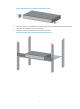
Installing the switch WARNING! Before installing or moving the switch, remove the power cord. You can install an HP 1920 switch in a 19-inch rack, on a workbench, or on a wall. Mounting the switch in a 19-inch rack by using mounting brackets 1. Wear an ESD wrist strap and make sure it makes good skin contact and is reliably grounded. 2. Verify that the rack is securely grounded and is stable. 3. Select mounting brackets for the switch. { { { 4.
Figure 3 Attaching Type-C mounting brackets to the switch 5. Place the switch on a rack shelf in the rack. Push the switch in until the oval holes in the brackets align with the mounting holes in the rack posts. 6. Attach the mounting brackets to the rack posts with screws.
Figure 5 Attaching Type-B mounting brackets to the rack post Figure 6 Attaching Type-C mounting brackets to the rack post 6
Mounting the switch on a workbench IMPORTANT: • Reserve a clearance of 10 cm (3.9 in) around the chassis for heat dissipation. • Do not place heavy objects on the switch. To mount the switch on a workbench: 1. Verify that the workbench is sturdy and reliably grounded. 2. Place the switch bottom up, and clean the round holes in the chassis bottom with a dry cloth. 3. Attach the rubber feet to the four round holes in the chassis bottom. 4. Place the switch upside up on the workbench.
Figure 9 Hole spacing 2. Insert one wall anchor into each hole until the anchors are flush with the wall surface. 3. Drive one screw into each wall anchor, and tighten the screws just enough to keep it secure in the wall anchor. Leave a minimum clearance of 1.5 mm (0.06 in) between the base of the screw head and the wall anchor so the switch can hang on the screws securely. Figure 10 Driving a screw into a wall anchor 4.
Connecting cables Connecting network cable Use crossover cable or straight through cable to connect a PC or other network devices to the Ethernet port of the switch. Figure 12 Connecting network cable Installing the SFP transceiver module and optical fibers CAUTION: • Hold the SFP transceiver module by its two sides when you install or remove the module. Do not touch the golden finger of the module. • Remove the optical fiber, if any, from a transceiver module before installing it.
Figure 13 Installing the SFP transceiver module and optical fibers Connecting the console cable To connect a terminal (for example, a PC) to the switch: 1. Wear an ESD wrist strap and make sure it makes good skin contact and is reliably grounded. 2. Connect the DB-9 female connector of the console cable to the serial port of the PC. 3. Connect the RJ-45 connector to the console port of the switch.
4. Connect one end of the AC power cord to the AC power receptacle on the switch. 5. Connect the other end of the AC power cord to the AC power outlet. 6. Examine the power LED. If it is ON, the power connection is correct. Figure 15 Connecting the AC power cord to the AC power receptacle Connecting the DC power cord IMPORTANT: Make sure the DC power cord is shorter than 3 m (9.84 ft). Only the HP 1920-24G-PoE+ (370W) supports DC RPS power.
Figure 16 Connecting the DC power cord to the DC power receptacle Verifying the installation After you complete the installation, verify the following items: • There is enough space for heat dissipation around the switch. • The rack or workbench is stable. • The grounding cable is securely connected. • The correct power source is used. • The power cords are correctly connected. • All the interface cables are cabled indoors.
Accessing the switch for the first time Setting up the configuration environment The first time you access the switch you must use a console cable to connect a console terminal, for example, a PC, to the console port on the switch. Figure 17 Connecting the console port to a terminal Connecting the console cable Console cable A console cable is an 8-core shielded cable.
Connection procedure CAUTION: The serial ports on PCs do not support hot swapping. To connect a PC to an operating switch, first connect the PC end. To disconnect a PC from an operating switch, first disconnect the switch end. To connect a terminal (for example, a PC) to the switch: 1. Wear an ESD wrist strap and make sure it makes good skin contact and is reliably grounded. 2. Connect the DB-9 female connector of the console cable to the serial port of the PC. 3.
3. Select the serial port to be used from the Connect using list, and click OK. Figure 20 Setting the serial port used by the HyperTerminal connection 4. Set Bits per second to 38400, Data bits to 8, Parity to None, Stop bits to 1, and Flow control to None, and click OK. Figure 21 Setting the serial port parameters 5. Select File > Properties in the HyperTerminal window.
Figure 22 HyperTerminal window 6. On the Settings tab, set the emulation to VT100 and click OK.
Powering on the switch Verification before power-on Before powering on the switch, verify the following items: • The power cord is correctly connected. • The input power voltage meets the requirement of the switch. • The console cable is correctly connected. • The terminal (for example, a PC) has started, and its configuration parameters have been correctly set. Powering on the switch Power on the switch (for example, an HP 1920-24G switch), and the following information is displayed: Starting......
............................................................................ ............................................................................ ............................................................................ ............................................................................ ............................................................................ ............................................................................ ..................................................
Support and other resources Contacting HP For worldwide technical support information, see the HP support website: http://www.hp.
Conventions This section describes the conventions used in this documentation set. Command conventions Convention Description Boldface Bold text represents commands and keywords that you enter literally as shown. Italic Italic text represents arguments that you replace with actual values. [] Square brackets enclose syntax choices (keywords or arguments) that are optional. { x | y | ... } Braces enclose a set of required syntax choices separated by vertical bars, from which you select one.
Network topology icons Represents a generic network device, such as a router, switch, or firewall. Represents a routing-capable device, such as a router or Layer 3 switch. Represents a generic switch, such as a Layer 2 or Layer 3 switch, or a router that supports Layer 2 forwarding and other Layer 2 features. Represents an access controller, a unified wired-WLAN module, or the switching engine on a unified wired-WLAN switch. Represents an access point. Represents a mesh access point.
Appendix A Chassis views and technical specifications Chassis views 1920-8G Figure 24 1920-8G front panel (1) 10/100/1000BASE-T copper ports (2) 100/1000BASE-X SFP fiber ports (3) Console port (4) Fiber port LEDs (5) Copper port LEDs (6) Power LED Figure 25 1920-8G rear panel (1) Grounding screw (2) AC power receptacle (3) Security slot 1920-16G Figure 26 1920-16G front panel (1) 10/100/1000BASE-T copper ports (2) 100/1000BASE-X SFP fiber ports (3) Fiber port LEDs (4) Copper port LEDs (5) Po
Figure 27 1920-16G rear panel (1) Grounding screw (2) AC power receptacle 1920-24G Figure 28 1920-24G front panel (1) 10/100/1000BASE-T copper ports (2) 100/1000BASE-X SFP fiber ports (3) Fiber port LEDs (4) Copper port LEDs (5) Power LED (6) Console port Figure 29 1920-24G rear panel (1) Grounding screw (2) AC power receptacle 1920-48G Figure 30 1920-48G front panel (1) 10/100/1000BASE-T copper ports (2) 100/1000BASE-X SFP fiber ports (3) Console port (4) Power LED 23
Figure 31 1920-48G rear panel (1) Grounding screw (2) AC power receptacle 1920-8G-PoE+ (65W) Figure 32 1920-8G-PoE+ (65W) front panel (1) 10/100/1000BASE-T copper ports (2) 100/1000BASE-X SFP fiber ports (3) Console port (4) Fiber port LEDs (5) Copper port LEDs (6) Power LED Figure 33 1920-8G-PoE+ (65W) rear panel (1) AC power receptacle (2) Grounding screw (3) Security slot 1920-8G-PoE+ (180W) Figure 34 1920-8G-PoE+ (180W) front panel (1) 10/100/1000BASE-T copper ports (2) 100/1000BASE-X SF
Figure 35 1920-8G-PoE+ (180W) rear panel 1 2 3 (1) AC power receptacle (2) Grounding screw (3) Security slot 1920-24G-PoE+ (180W) Figure 36 1920-24G-PoE+ (180W) front panel (1) 10/100/1000BASE-T copper ports (2) 100/1000BASE-X SFP fiber ports (3) Fiber port LEDs (4) Copper port LEDs (5) Power LED (6) Console port Figure 37 1920-24G-PoE+ (180W) rear panel (1) Grounding screw (2) AC power receptacle 1920-24G-PoE+ (370W) Figure 38 1920-24G-PoE+ (370W) front panel (1) 10/100/1000BASE-T copper
Figure 39 1920-24G-PoE+ (370W) rear panel (1) Grounding screw (2) AC power receptacle (3) DC power receptacle Physical specifications Chassis dimensions and weights Chassis Dimensions (H x W x D) Maximum weight 1920-8G 44 x 266 x 162 mm (1.73 x 10.47 x 6.38 in) 1 kg (2.20 lb) 1920-16G 44 x 440 x 173 mm (1.73 x 17.32 x 6.81 in) 2.1 kg (4.63 lb) 1920-24G 44 x 440 x 173 mm (1.73 x 17.32 x 6.81 in) 2.2 kg (4.85 lb) 1920-8G-PoE+ (65W) 44 x 330 x 230 mm (1.73 x 12.99 x 9.06 in) 2.1 kg (4.
Environmental specifications Chassis Operating temperature Relative humidity All chassis 0°C to 40°C (32°F to 104°F) 5% to 95%, noncondensing Power specifications AC input voltage specifications Chassis Rated voltage range All chassis 100 VAC to 240 VAC @ 50 Hz or 60 Hz RPS DC input voltage specifications and RPS compatibility Chassis RPS input rated voltage range 1920-24G-PoE+ (370W) –54 VDC to –57 VDC Power consumption specifications for non-PoE switches Chassis Minimum power consumption M
Chassis 1920-24G-PoE (370W) Maximum PoE power per port 30 W Maximum PoE ports at full 30 W output Total PoE output 370 W at AC input 12 at AC input 24 at RPS DC input 740 W at RPS DC input Minimum power consumption Maximum power consumption (including total PoE output) 18.
Appendix B LEDs Power LED Table 5 Power LED description Status Description Steady green The switch is powered on and the power supply is operating correctly. Flashing green The switch is powered on and is performing the self-test. Off The switch is not powered on or the power supply is faulty. Copper port LEDs Link/ACT LEDs Table 6 Link/ACT LED description Status Description Steady yellow A 10/100-Mbps link is present. Flashing yellow The port is receiving or sending data at 10/100 Mbps.
Status Description Steady green A 1000-Mbps link is present. Flashing green The port is receiving or sending data at 1000 Mbps. Off No link is present. RPS LED Only the HP 1920-24G-PoE+ (370W) supports the RPS. Table 9 RPS power LED description Status Description Steady green The RPS is supplying power correctly. Off No RPS is used or the RPS is supplying power incorrectly.
Appendix C Troubleshooting Table 10 describes the troubleshooting methods for common issues that you might encounter while using and managing the switch. If a problem persists, contact HP Support. Table 10 Troubleshooting methods Symptom Power LED off LAN interface LED off Troubleshooting method 1. Verify that the correct power source is used and the power cords are correctly connected. 2. Verify that the power source side provides power supply correctly. 1.