
User's Manual


71
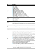
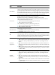
Item Descri
p
tion
Speed
Set the transmission speed of the port:
• 10—10 Mbps.
• 100—100 Mbps.
• 1000—1000 Mbps.
• Auto—Autonegotiation.
• Auto 10—Autonegotiated to 10 Mbps.
• Auto 100—Autonegotiated to 100 Mbps.
• Auto 1000—Autonegotiated to 1000 Mbps.
• Auto 10 100—Autonegotiated to 10 or 100 Mbps.
• Auto 10 1000—Autonegotiated to 10 or 1000 Mbps.
• Auto 100 1000—Autonegotiated to 100 or 1000 Mbps.
• Auto 10 100 1000—Autonegotiated to 10, 100, or 1000 Mbps.
Duplex
Set the duplex mode of the port:
• Auto—Autonegotiation.
• Full—Full duplex.
• Half—Half duplex.
Link Type
Set the link type of the current port, which can be access, hybrid, or trunk. For more
information, see "Configuring VLANs."
T
o change the link type of a port from trunk to hybrid, or vice versa, you must first set its link
type to access.
PVID
Set the port VLAN ID (PVID) of the interface. For more information about setting the PVID,
see "Configuring VLANs."
To make
sure a link correctly transmits packets, the trunk or hybrid ports at the two ends of
the link must have the same PVID.
Description Set the description of the port.
MDI
Set the MDI mode of the port.
You can use two types of Ethernet cables to connect Ethernet devices: crossover cable and
straight-through cable. To accommodate these two types of cables, an Ethernet port can
operate in one of the following three MDI modes: across, normal, and auto.
An Ethernet port is composed of eight pins. By default, each pin has its particular role. For
example, pin 1 and pin 2 are used for transmitting signals, and pin 3 and pin 6 are used
for receiving signals. You can change the pin roles by setting the MDI mode.
• For an Ethernet port in across mode, pin 1 and pin 2 are used for transmitting signals,
and pin 3 and pin 6 are used for receiving signals. The pin roles are not changed.
• For an Ethernet port in auto mode, the pin roles are decided through autonegotiation.
• For an Ethernet port in normal mode, the pin roles are changed. Pin 1 and pin 2 are
used for receiving signals, and pin 3 and pin 6 are used for transmitting signals.
To enable normal communication, you must connect the local transmit pins to the remote
receive pins. Configure the MDI mode depending on the cable types.
When you configure the MID mode, follow these guidelines:
• Typically, use the auto mode. The other two modes are used only when the device
cannot determine the cable type.
• When straight-through cables are used, the local MDI mode must be different from the
remote MDI mode.
• When crossover cables are used, the local MDI mode must be the same as the remote
MDI mode, or the MDI mode of at least one end must be set to auto.