
User's Manual

190
• Loop guard
• TC-BPDU (a message that notifies the device of topology changes) guard
• Support for the hot swapping of interface boards and switchover of the active and standby main
boards.
Protocols and standards
MSTP is documented in the following protocols and standards:
• IEEE 802.1d, Spanning Tree Protocol
• IEEE 802.1w, Rapid Spanning Tree Protocol
• IEEE 802.1s, Multiple Spanning Tree Protocol
Configuration guidelines
When you configure MSTP, follow these guidelines:
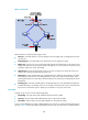
• Two or more spanning tree devices belong to the same MST region only if they are configured to
have the same MST region name, MST region level, and the same VLAN-to-instance mapping
entries in the MST region, and they are connected through a physical link.
• If two or more devices are selected as the root bridge in a spanning tree at the same time, the device
with the lowest MAC address is chosen.
• If BPDU guard is disabled, a port set as an edge port becomes a non-edge port again if it receives
a BPDU from another port. To restore its port role as an edge port, you must restart the port.
• If a port directly connects to a user terminal, configure it as an edge port and enable BPDU guard
for it. This enables the port to quickly transit to the forwarding state when ensuring network security.
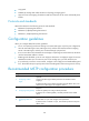
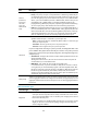
Recommended MSTP configuration procedure
Ste
p
Remarks
1. Configuring an MST
region.
Optional.
Configure the MST region-related parameters and VLAN-to-instance
mappings.
By default, the MST region-related parameters adopt the default values, and
all VLANs in an MST region are mapped to MSTI 0.
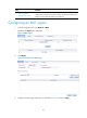
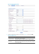
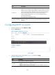
2. Configuring MSTP globally.
Required.
Enable STP globally and configure MSTP parameters.
By default, STP is enabled globally. All MSTP parameters have default
values.
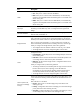
3. Configuring MSTP on a
port.
Optional.
Enable MSTP on a port and configure MSTP parameters.
By default, MSTP is enabled on a port, and all MSTP parameters adopt the
default values.