HP Elite x2 1012 G1 Tablet HP Elite x2 1012 G1 Tablet with Advanced Keyboard HP Elite x2 1012 G1 Tablet with Travel Keyboard Maintenance and Service Guide IMPORTANT! This document is intended for HP authorized service providers only.
© Copyright 2016 HP Development Company, L.P. Intel and Skylake are trademarks of Intel Corporation in the U.S. and other countries. Microsoft and Windows are U.S. registered trademarks of Microsoft Corporation. Product notice This guide describes features that are common to most models. Some features may not be available on your computer. The information contained herein is subject to change without notice.
Safety warning notice WARNING! To reduce the possibility of heat-related injuries or of overheating the device, do not place the device directly on your lap or obstruct the device air vents. Use the device only on a hard, flat surface. Do not allow another hard surface, such as an adjoining optional printer, or a soft surface, such as pillows or rugs or clothing, to block airflow. Also, do not allow the AC adapter to contact the skin or a soft surface, such as pillows or rugs or clothing, during operation.
iv Safety warning notice
Table of contents 1 Product description ....................................................................................................................................... 1 2 External component identification .................................................................................................................. 5 Tablet edge components ....................................................................................................................................... 5 Display ............
Back cover ......................................................................................................................................... 30 Display panel ..................................................................................................................................... 31 Touch controller board ...................................................................................................................... 33 WLAN module ....................................................
8 Using HP PC Hardware Diagnostics (UEFI) ....................................................................................................... 70 Downloading HP PC Hardware Diagnostics (UEFI) to a USB device .................................................................... 70 9 Specifications .............................................................................................................................................. 72 Computer specifications ..........................................
viii
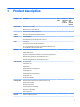
1 Product description Category Description 1012 Tablet Product Name HP Elite x2 1012 G1 Tablet √ HP Elite x2 1012 G1 Travel Keyboard HP Elite x2 1012 G1 Advanced Keyboard Chipset Intel Skylake Premium PCH (integrated with CPU) Graphics Internal graphics: 1012 tablet with Travel Keyboard 1012 tablet with Advanced Keyboard √ √ Intel UMA Graphics (GT2) (with shared video memory) Panel Touch screen Corning Gorilla 4 Glass, GF2-MM, Direct Bonded 12.0” 3:2 (LED backlight – Ultra-Slim): 12.
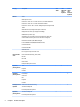
Category Description Wireless WLAN: 1012 Tablet 1012 tablet with Travel Keyboard 1012 tablet with Advanced Keyboard WLAN options via M.2: Intel® 802.11 2x2ac + BT 4.1 Combo (non-vPro)- Snowfield Peak 8260 Intel® 802.11 2x2ac + BT 4.1 Combo Snowfield Peak 8260 Intel® 802.11 2x2 AC + BT 4.
Category Description Power requirements Battery 1012 Tablet 1012 tablet with Travel Keyboard 1012 tablet with Advanced Keyboard Slate: 4-cell Long Life Polymer 40 Whr (2.86Ahr) Base: None AC adapter: (USB Type-C) 45W "Smart" AC Adapter non-PFC USB-C Power Cord, localized Duckhead for use in United States and South Korea Duckhead Power Cord for use in all countries except South Korea Security TPM 1.2/2.
Category Description Windows 8.1 Emerging Markets 64 Windows 8.1 Multi-Language 64 Windows 8.
2 External component identification Tablet edge components Component Description (1) Speakers Produce sound. (2) Internal microphones Record sound. (3) Audio-out (headphone)/Audio-in (microphone) combo jack Connects optional powered stereo speakers, headphones, earbuds, a headset, or a television audio cable. Also connects an optional headset microphone. This jack does not support optional microphone-only devices.
Component Description WARNING! To reduce the risk of personal injury, adjust the volume before using headphones, earbuds, or a headset. For additional safety information, see the Regulatory, Safety and Environmental Notices. To access this guide: ▲ Select the Start button, select All apps, select HP Help and Support, and then select HP Documentation. NOTE: When a device is connected to the jack, the tablet speakers are disabled. (4) USB 3.
Component Description ● When the tablet is in the Sleep state, press the button briefly to exit Sleep. CAUTION: Pressing and holding down the power button results in the loss of unsaved information. NOTE: Although you can turn off the tablet with the power button, the recommended procedure is to use the Windows Shut down command. To learn more about your power settings, see your power options. ▲ Type power in the taskbar search box, and then select Power and sleep settings.
Display Component Description (1) WWAN antennas* (select products only) Send and receive wireless signals to communicate with wireless wide area networks (WWANs). (2) WiGig antenna* Sends and receives wireless signals to the Wireless Dock (WiDock). The WiDock is a wireless gigabit (WiGig) device that connects the tablet to other wireless devices located within 0.6 m to 1.2 m (2 ft to 4 ft) of the WiDock. (3) Webcam Records video and captures photographs.
Back Component Description (1) Camera flash Provides a camera flash. You can control the flash using the Windows Metro Camera app. (2) Webcam (rear) Records video and captures photographs. Some products allow you to video conference and chat online using streaming video. (3) Fingerprint reader (select products only) Allows a fingerprint logon to Windows, instead of a password logon. (4) Kickstand Provides stability and the best viewing angle.
Using the kickstand To change the angle for the display, follow these steps: 1. Hold the tablet with top edge up (the speakers are on top). 2. Slide the kickstand away from the tablet and position the kickstand at the desired angle. The kickstand will hold at a midway point (1) of about 52 degrees or at full stopping point (2) of about 118 degrees. To close the kickstand, push the kickstand against the bottom of the tablet until it is flush with the bottom.
Keyboard base components (select products only) Your tablet supports an optional keyboard. This section provides information about the common features of the supported keyboards. NOTE: Keyboard appearance and features might vary. TouchPad Component Description (1) TouchPad on/off button Turns the TouchPad on and off. (2) TouchPad light ● On: The TouchPad is off. ● Off: The TouchPad is on. (3) TouchPad zone Reads your finger gestures to move the pointer or activate items on the screen.
Lights Component Description (1) Caps lock light ● On: Caps lock is on, which switches the keys to all capital letters. (2) TouchPad light ● On: The TouchPad is off. ● Off: The TouchPad is on. ● Amber: Sound is off. ● Off: Sound is on. ● Amber: microphone sound is off. ● Off: microphone sound is on. (3) (4) (5) Mute light Microphone mute light Wireless light On: An integrated wireless device, such as a wireless local area network (WLAN) device and/or a Bluetooth® device, is on.
Special function keys Component Description (1) esc key Displays system information when pressed in combination with the fn key. (2) fn key Executes frequently used system functions when pressed in combination with a function key, the num lock key, or the esc key. (3) Windows key Opens the Start menu. NOTE: Pressing the Windows key again will close the Start menu. (4) Function keys Execute frequently used system functions when pressed in combination with the fn key.
Using the hot keys To use a hot key: ▲ Press the fn key, and then press the correct function key represented by the icons below. Press fn+function key Description Initiates Sleep, which saves your information in system memory. The display and other system components turn off and power is conserved. To exit Sleep, briefly press the power button. CAUTION: To reduce the risk of information loss, save your work before initiating Sleep.
NFC and Smart Card (select products only) Component Description (1) Smart card reader Supports optional Smart cards. (2) Near Field Communication (NFC) antenna* and NFC tapping area Send and receive wireless signals to communicate and transfer data/info to and from your NFC-compatible devices. *The antenna is not visible from the outside of the keyboard. For optimal transmission, keep the areas immediately around the antenna free from obstructions.
Connecting the tablet to the keyboard base To connect the tablet to the keyboard base, follow these steps: 1. Insert the tablet POGO pin connector docking port into the keyboard base POGO pin docking connector. 2. Position the kickstand at the desired angle. NOTE: If you close the kickstand, you can leave the keyboard attached and position the keyboard behind the tablet. The keyboard keys and TouchPad are locked to prevent you from accidently typing while the keyboard is in this position.
Removing the keyboard base from the tablet To remove the keyboard base from the tablet, pull the keyboard away from the tablet. Locating system information The labels affixed to the tablet provide information you may need when you troubleshoot system problems or travel internationally with the tablet. IMPORTANT: section. ● Check the bottom of the tablet and the back of the display for the labels described in this Service label—Provides important information to identify your tablet.
Component 18 (1) Model name (select products only) (2) Product number (3) Serial number (4) Warranty period ● Regulatory label(s)—Provide(s) regulatory information about the tablet. ● Wireless certification label(s)—Provide(s) information about optional wireless devices and the approval markings for the countries or regions in which the devices have been approved for use.
3 Illustrated parts catalog Computer major components NOTE: HP continually improves and changes product parts. For complete and current information on supported parts for your computer, go to http://partsurfer.hp.com, select your country or region, and then follow the on-screen instructions. NOTE: Details about your computer, including model, serial number, product key, and length of warranty, are on the service tag at the bottom of your computer. See Locating system information on page 17 for details.
Item Component Spare part number MU736 HS3110 HSPA+ w/GPS M.s 822828-001 WWAN antenna 844870-001 (5) Rear webcam 844883-001 (6) WLAN module WIGIG Module W/Bracket W/Cable 844884-001 11ac 2x2 INT 8260NGW SnfP2 806721-001 11ac 2x2 INT 8260NGW SnfP2NV 806722-001 INT 802.
Item Component Spare part number UMA graphics M5-6Y578GBfWWANx2 1012 G1 with Windows operating system and WWAN capability 845473-601 UMA graphics M7-6Y758GBfWWANx2 1012 G1 with Windows operating system and WWAN capability 845474-601 (13) POGO connector (includes cable) 844877-001 (14) Speaker 844881-001 (15) Fingerprint reader 844875-001 (16) Hall sensor 844874-001 (17) Back cover 844871-001 (18) Kickstand (included with back cover) Miscellaneous parts Component Spare part number A
22 Component Spare part number For use in Japan 349756-004 For use in NEMA 213349-012 For use in Africa 361240-004 For use in Switzerland 213354-010 For use in Taiwan 393313-005 For use in Thailand 285096-009 For use in the United Kingdom 213351-010 HP Active Pen with App Launch (selct products only) 846410-001 Screw Kit 844880-001 Chapter 3 Illustrated parts catalog
4 Removal and replacement procedures preliminary requirements Tools required You will need the following tools to complete the removal and replacement procedures: ● Flat-bladed screwdriver ● Magnetic screwdriver ● Phillips P0 and P1 screwdrivers Service considerations The following sections include some of the considerations that you must keep in mind during disassembly and assembly procedures.
Cables and connectors CAUTION: When servicing the computer, be sure that cables are placed in their proper locations during the reassembly process. Improper cable placement can damage the computer. Cables must be handled with extreme care to avoid damage. Apply only the tension required to unseat or seat the cables during removal and insertion. Handle cables by the connector whenever possible. In all cases, avoid bending, twisting, or tearing cables.
Grounding guidelines Electrostatic discharge damage Electronic components are sensitive to electrostatic discharge (ESD). Circuitry design and structure determine the degree of sensitivity. Networks built into many integrated circuits provide some protection, but in many cases, ESD contains enough power to alter device parameters or melt silicon junctions. A discharge of static electricity from a finger or other conductor can destroy static-sensitive devices or microcircuitry.
Packaging and transporting guidelines Follow these grounding guidelines when packaging and transporting equipment: ● To avoid hand contact, transport products in static-safe tubes, bags, or boxes. ● Protect ESD-sensitive parts and assemblies with conductive or approved containers or packaging. ● Keep ESD-sensitive parts in their containers until the parts arrive at static-free workstations. ● Place items on a grounded surface before removing items from their containers.
Equipment guidelines Grounding equipment must include either a wrist strap or a foot strap at a grounded workstation. ● When seated, wear a wrist strap connected to a grounded system. Wrist straps are flexible straps with a minimum of one megohm ±10% resistance in the ground cords. To provide proper ground, wear a strap snugly against the skin at all times. On grounded mats with banana-plug connectors, use alligator clips to connect a wrist strap.
5 Removal and replacement procedures for Authorized Service Provider parts This chapter provides removal and replacement procedures for Authorized Service Provider only parts. CAUTION: Components described in this chapter should only be accessed by an authorized service provider. Accessing these parts can damage the computer or void the warranty. CAUTION: This computer does not have user-replaceable parts.
Keyboard (select products only) Description Spare part number Keyboard base with TouchPad 846748-001 Advanced Keyboard base 850487-001 For use in country or region Spare part number For use in country or region Spare part number For use in country or region Spare part number Belgium -A41 India -D61 Saudi Arabia -171 Brazil -201 Israel -BB1 Slovenia -BA1 Bulgaria -261 Italy -061 South Korea -AD1 Canada -DB1 Japan -291 Spain -071 Czech Republic and Slovakia -FL1 Latin Ame
Back cover Description Spare part number Back cover 844871-001 IMPORTANT: Make special note of each screw and screw lock size and location during removal and replacement. Before removing the back cover, follow these steps: 1. Turn off the computer. If you are unsure whether the computer is off or in Hibernation, turn the computer on, and then shut it down through the operating system. 2. Disconnect the power from the computer by unplugging the power cord from the computer. 3.
Display panel Description Spare part number Panel 844861-001 Display Cable Kit 844872-001 IMPORTANT: Make special note of each screw and screw lock size and location during removal and replacement. Before removing the display panel, follow these steps: 1. Turn off the computer. If you are unsure whether the computer is off or in Hibernation, turn the computer on, and then shut it down through the operating system. 2.
2. Disconnect the touch board cable (1) and the display cable (2), and then remove the display panel (3). Reverse this procedure to replace the display panel.
Touch controller board IMPORTANT: Make special note of each screw and screw lock size and location during removal and replacement. Description Spare part number Touch controller board 844861-001 Before removing the touch controller board, follow these steps: 1. Turn off the computer. If you are unsure whether the computer is off or in Hibernation, turn the computer on, and then shut it down through the operating system. 2.
WLAN module IMPORTANT: Make special note of each screw and screw lock size and location during removal and replacement. Description Spare part number WLAN module WIGIG Module W/Bracket W/Cable 844884-001 11ac 2x2 INT 8260NGW SnfP2 806721-001 11ac 2x2 INT 8260NGW SnfP2NV 806722-001 INT 802.11AC 18260+BT4 2x2 810814-005 WLAN antenna 844869-001 Before removing the WLAN module, follow these steps: 1. Turn off the computer.
Reverse this procedure to replace the WLAN module.
WWAN module (select products only) IMPORTANT: Make special note of each screw and screw lock size and location during removal and replacement.
Reverse this procedure to replace the WWAN module (select products only).
Solid-state drive Description Spare part number Solid-state drive 128 GB SATA-3 TLC 844862-001 180 GB SATA-3 TLC 844863-001 180 GB SATA-3 self-encrypting drive OPAL2 844864-001 256 GB SATA-3 TLC 844865-001 256 GB SATA-3 self-encrypting drive OPAL2 844866-001 256 GB PCIe-3x4 NVMe 844868-001 512 GB SATA-3 TLC 844867-001 IMPORTANT: Make special note of each screw and screw lock size and location during removal and replacement. Before removing the solid-state drive, follow these steps: 1.
2. Slide the solid-state drive (2) to the right, and then lift the solid-state drive to remove it. Reverse this procedure to replace the solid-state drive.
Kickstand Description Kickstand (included with Back cover spare part kit, 844871-001 (see Back cover on page 30). IMPORTANT: Make special note of each screw and screw lock size and location during removal and replacement. Before removing the display panel, follow these steps: 1. Turn off the computer. If you are unsure whether the computer is off or in Hibernation, turn the computer on, and then shut it down through the operating system. 2.
2. Lift the kickstand to remove it. Reverse this procedure to replace the kickstand.
Battery Description Spare part number 4-cell Long Life Polymer 40 Whr (2.86Ahr) Battery 812205-001 IMPORTANT: Make special note of each screw and screw lock size and location during removal and replacement. Before removing the display panel, follow these steps: 1. Turn off the computer. If you are unsure whether the computer is off or in Hibernation, turn the computer on, and then shut it down through the operating system. 2.
3. Disconnect the battery cable (3), and then lift the battery (4) to remove it. Reverse this procedure to replace the battery.
Microphone board Description Spare part number Microphone board 844878-001 IMPORTANT: Make special note of each screw and screw lock size and location during removal and replacement. Before removing the display panel, follow these steps: 1. Turn off the computer. If you are unsure whether the computer is off or in Hibernation, turn the computer on, and then shut it down through the operating system. 2. Disconnect the power from the computer by unplugging the power cord from the computer. 3.
Reverse this procedure to replace the microphone board.
Rear webcam Description Spare part number Rear webcam 844883-001 IMPORTANT: Make special note of each screw and screw lock size and location during removal and replacement. Before removing the display panel, follow these steps: 1. Turn off the computer. If you are unsure whether the computer is off or in Hibernation, turn the computer on, and then shut it down through the operating system. 2. Disconnect the power from the computer by unplugging the power cord from the computer. 3.
Front webcam Description Spare part number Front webcam 844882-001 IMPORTANT: Make special note of each screw and screw lock size and location during removal and replacement. Before removing the display panel, follow these steps: 1. Turn off the computer. If you are unsure whether the computer is off or in Hibernation, turn the computer on, and then shut it down through the operating system. 2. Disconnect the power from the computer by unplugging the power cord from the computer. 3.
USB Type-C bracket Description USB type-C bracket (included with System Board. See System board on page 50). IMPORTANT: Make special note of each screw and screw lock size and location during removal and replacement. Before removing the display panel, follow these steps: 1. Turn off the computer. If you are unsure whether the computer is off or in Hibernation, turn the computer on, and then shut it down through the operating system. 2.
Reverse this procedure to replace the USB type-C bracket.
System board Description Spare part number System board UMA graphics M3-6Y30 4GBx2 1012 G1 with Windows operating system 844858-601 UMA graphics M3-6Y30 4GB fWWANx2 1012 G1 with Windows operating system and WWAN capability 845470-601 UMA graphics M5-6Y54 4GBx2 1012 G1 with Windows operating system 845483-601 UMA graphics M5-6Y54 4GBx2 1012 G1 with Windows operating system and WWAN capability 845484-601 UMA graphics M5-6Y54 8GBx2 1012 G1 with Windows operating system 845485-601 UMA graphics M5-6Y
4. Disconnect fingerprint reader cable (4). 5. Remove 7 Phillips M1.6x3.screws (1), and then lift the system board to remove it (2). Reverse this procedure to replace the system board.
Button board Description Spare part number Button board For products with WWAN capability 844876-001 For products without WWAN capability 848827-001 IMPORTANT: Make special note of each screw and screw lock size and location during removal and replacement. Before removing the display panel, follow these steps: 1. Turn off the computer. If you are unsure whether the computer is off or in Hibernation, turn the computer on, and then shut it down through the operating system. 2.
Reverse this procedure to replace the button board.
Fingerprint reader board Description Spare part number Fingerprint reader board (includes cable) 844875-001 IMPORTANT: Make special note of each screw and screw lock size and location during removal and replacement. Before removing the display panel, follow these steps: 1. Turn off the computer. If you are unsure whether the computer is off or in Hibernation, turn the computer on, and then shut it down through the operating system. 2.
Reverse this procedure to replace the fingerprint reader board.
POGO connector Description Spare part number POGO connector 844877-001 IMPORTANT: Make special note of each screw and screw lock size and location during removal and replacement. Before removing the display panel, follow these steps: 1. Turn off the computer. If you are unsure whether the computer is off or in Hibernation, turn the computer on, and then shut it down through the operating system. 2. Disconnect the power from the computer by unplugging the power cord from the computer. 3.
2. Release the cable, which is secured with tape, and lift the cable and connector to remove them (2). Reverse this procedure to replace the POGO connector.
Speaker Description Spare part number Speaker 844881-001 IMPORTANT: Make special note of each screw and screw lock size and location during removal and replacement Before removing the display panel, follow these steps: 1. Turn off the computer. If you are unsure whether the computer is off or in Hibernation, turn the computer on, and then shut it down through the operating system. 2. Disconnect the power from the computer by unplugging the power cord from the computer. 3.
2. Use a nylon pry tool carefully to release the speaker/antenna assembly (2). Reverse this procedure to replace the speaker.
6 Backup and recovery This chapter provides information about the following processes. The information in the chapter is standard procedure for most products. ● Creating recovery media and backups ● Restoring and recovering your system For additional information, refer to the HP support assistant app. ▲ Type support in the taskbar search box, and then select the HP Support Assistant app. ‒ or – Select the question mark icon in the taskbar.
You can use Windows tools to create system restore points and create backups of personal information, see Using Windows tools on page 61. ● If your tablet does list the Recovery partition and the Windows partition, you can use HP Recovery Manager to create recovery media after you successfully set up the tablet. HP Recovery media can be used to perform system recovery if the hard drive becomes corrupted.
Restore and recovery There are several options for recovering your system. Choose the method that best matches your situation and level of expertise: IMPORTANT: ● Windows offers several options for restoring from backup, refreshing the tablet, and resetting the tablet to its original state. For more information see the Get started app. ▲ ● Not all methods are available on all products. Select the Start button, and then select the Get started app.
IMPORTANT: HP Recovery Manager does not automatically provide backups of your personal data. Before beginning recovery, back up any personal data you want to retain. Using HP Recovery media, you can choose from one of the following recovery options: NOTE: Only the options available for your tablet display when you start the recovery process. ● System Recovery—Reinstalls the original operating system, and then configures the settings for the programs that were installed at the factory.
To change the boot order: IMPORTANT: For a tablet with a detachable keyboard, connect the keyboard to the keyboard dock before beginning these steps. 1. Insert the HP Recovery media. 2. Access BIOS: For tablets with keyboards attached: ▲ Turn on or restart the tablet, quickly press esc, and then press f9 for boot options. For tablets without keyboards: ▲ Turn on or restart the tablet, and then quickly hold down the volume down button; then select f9. 3.
7 Computer Setup (BIOS), TPM, and HP Sure Start Using Computer Setup Computer Setup, or Basic Input/Output System (BIOS), controls communication between all the input and output devices on the system (such as disk drives, display, keyboard, mouse, and printer). Computer Setup includes settings for the types of devices installed, the startup sequence, and the amount of system and extended memory. NOTE: Use extreme care when making changes in Computer Setup.
To exit Computer Setup menus, choose one of the following methods: ● To exit Computer Setup menus without saving your changes: Select the Exit icon in the lower-right corner of the screen, and then follow the on-screen instructions. – or – Select Main, select Ignore Changes and Exit, and then press enter. ● To save your changes and exit Computer Setup menus: Select the Save icon in the lower-right corner of the screen, and then follow the on-screen instructions.
Updating the BIOS Updated versions of the BIOS may be available on the HP website. Most BIOS updates on the HP website are packaged in compressed files called SoftPaqs. Some download packages contain a file named Readme.txt, which contains information regarding installing and troubleshooting the file. Determining the BIOS version To decide whether you need to update Computer Setup (BIOS), first determine the BIOS version on your tablet.
NOTE: If you connect your tablet to a network, consult the network administrator before installing any software updates, especially system BIOS updates. BIOS installation procedures vary. Follow any instructions that are revealed on the screen after the download is complete. If no instructions are revealed, follow these steps: 1. Type file in the taskbar search box, and then select File Explorer. 2. Select your hard drive designation. The hard drive designation is typically Local Disk (C:). 3.
Using HP Sure Start (select products only) Select models are configured with HP Sure Start, a technology that continuously monitors the BIOS for attacks or corruption. If the BIOS becomes corrupted or is attacked, HP Sure Start automatically restores the BIOS to its previously safe state, without user intervention. HP Sure Start is configured and already enabled so that most users can use the HP Sure Start default configuration. The default configuration can be customized by advanced users.
8 Using HP PC Hardware Diagnostics (UEFI) HP PC Hardware Diagnostics is a Unified Extensible Firmware Interface (UEFI) that allows you to run diagnostic tests to determine whether the computer hardware is functioning properly. The tool runs outside the operating system so that it can isolate hardware failures from issues that are caused by the operating system or other software components.
Download any version of UEFI for a specific product 1. Go to http://www.hp.com/support, and then select your country. The HP Support page is displayed. 2. Select Software and Drivers. 3. Use the categories listed to find your product. – or – Select Find Now to let HP automatically detect your product. 4. Select your tablet, and then select your operating system. 5. In the Diagnostic section, follow the on-screen instructions to select and download the UEFI version you want.
9 Specifications Computer specifications Slate Slate and Thin Keyboard Slate and Productivity Keyboard Width 300.0mm (11.81") 300.0mm (11.81") 300.0mm (11.81") Depth 213.85mm (8.42") 213.85mm (8.42") 213.85mm (8.42") Height (front to back) 8.05mm (0.32") 13.45mm (0.53") 16.45mm (0.65") Weight 1.81lb (820g) 2.67 lb (1210 g) 2.
Display specifications Internal Touch screen 12.0" diagonal LED-backlit BV UWVA eDP 1.3 Ultra-slim (1920 x 1280 – Full HD*) Touch screenChemically-strengthened Corning® Gorilla® Glass 4 top cover directly bonded to display Brightness 200 nits 340 nits (typical) Pixel resolution Format 1920 x 1280 (WUXGA+) Configuration RGB stripe Interface eDP 1.3 LCD Mode IPS/FFS/VA PPI 192 ppi Viewing angle UWVA 85/85/85/85 (Left/Right/Down/Up) Solid-state drive specifications Internal Storage* Supports M.
Memory 8GB Total System Memory Maximum 74 Chapter 9 Specifications Up to 8 GB
10 Power cord set requirements The wide-range input feature of the computer permits it to operate from any line voltage from 100 to 120 volts AC, or from 220 to 240 volts AC. The 3-conductor power cord set included with the computer meets the requirements for use in the country or region where the equipment is purchased. Power cord sets for use in other countries and regions must meet the requirements of the country or region where the computer is used.
76 Country/region Accredited agency Applicable note number Sweden SEMKO 1 Switzerland SEV 1 Taiwan BSMI 4 The United Kingdom BSI 1 The United States UL 2 1. The flexible cord must be Type HO5VV-F, 3-conductor, 1.0-mm² conductor size. Power cord set fittings (appliance coupler and wall plug) must bear the certification mark of the agency responsible for evaluation in the country or region where it will be used. 2. The flexible cord must be Type SPT-3 or equivalent, No.
11 Statement of memory volatility The purpose of this chapter is to provide general information regarding nonvolatile memory in HP Business PCs. This chapter also provides general instructions for restoring nonvolatile memory that can contain personal data after the system has been powered off and the hard drive has been removed. HP Business PC products that use Intel®-based or AMD®-based system boards contain volatile DDR memory.
g. If a DriveLock password is set, select the Security menu, and scroll down to Hard Drive Utilities under the Utilities menu. Select Hard Drive Utilities, select DriveLock, then uncheck the checkbox for DriveLock password on restart. Select OK to proceed. h. Select the Main menu, and then select Reset BIOS Security to factory default. Click Yes at the warning message. The computer will reboot. i.
NOTE: If the system has a BIOS administrator password, enter the password at the prompt. 2. a. Select Main, select Restore Defaults, and then select Yes to load defaults. b. Select the Security menu, select Restore Security Level Defaults, and then select Yes to restore security level defaults. c. If an asset or ownership tag is set, select the Security menu and scroll down to the Utilities menu. Select System IDs, and then select Asset Tracking Number.
NOTE: The amount of time it takes for Disk Sanitizer to run can take several hours. Plug the computer into an AC outlet before starting. 80 a. Turn on or restart the computer, and then press esc while the “Press the ESC key for Startup Menu” message is displayed at the bottom of the screen. b. Select the Security menu and scroll down to the Utilities menu. c. Select Hard Drive Tools. d.
Nonvolatile memory usage Nonvolatile Memory Type Amount (Size) Does this memory store customer data? Does this memory retain data when power is removed? What is the purpose of this memory? How is data input into this memory? How is this memory write-protected? HP Sure Start flash (select models only) 2 MBytes No Yes Provides protected backup of critical System BIOS code, EC firmware, and critical PC configuration data for select platforms that support HP Sure Start.
Nonvolatile Memory Type Amount (Size) Does this memory store customer data? Does this memory retain data when power is removed? What is the purpose of this memory? How is data input into this memory? How is this memory write-protected? the on-screen instructions. 82 Intel Management 1.5 MBytes or 5 Engine Firmware MBytes (present in only specific ZBook and EliteBook models. For more information, go to http://www.hp.com/ support. Select Find your product, and then follow the onscreen instructions.
Questions and answers 1. How can the BIOS settings be restored (returned to factory settings)? IMPORTANT: Restore defaults does not securely erase any data on your hard drive. See question and answer 6 for steps to securely erase data. Restore defaults does not reset the Custom Secure Boot keys. See question and answer 7 for information about resetting the keys. 2. a.
IMPORTANT: Resetting will result in the loss of information. These steps will not reset Custom Secure Boot Keys. See question and answer 7 for information about resetting the keys. 7. a. Turn on or restart the computer, and then press esc while the “Press the ESC key for Startup Menu” message is displayed at the bottom of the screen. b. Select Main, and then select Reset BIOS Security to Factory Default. c. Follow the on-screen instructions. d.
12 Recycling When a non-rechargeable or rechargeable battery has reached the end of its useful life, do not dispose of the battery in general household waste. Follow the local laws and regulations in your area for battery disposal. HP encourages customers to recycle used electronic hardware, HP original print cartridges, and rechargeable batteries.
Index A AC adapter and battery 6 AC adapter, spare part numbers spare part number 21 audio, product description 1 audio-out (headphone)/audio-in (microphone) combo jack identifying 5 B back cover 30 spare part number 21 spare part numbers 30 backups 60 battery 42 spare part numbers 19, 42 BIOS determining version 67 downloading an update 67 updating 67 Bluetooth label 18 boot order changing 63 bottom 18 button power 6 volume down 6 volume up 6 button board 52 spare part numbers 20, 52 C camera flash, identi
L labels Bluetooth 18 regulatory 18 serial number 17 wireless certification 18 WLAN 18 legacy support, USB 65 lights AC adapter and battery light microphone mute 12 num lock 12 TouchPad 12 webcam 8, 9 wireless 12 6 M memory nonvolatile 77 specifications 73 volatile 77 memory module product description 1 microphone product description 1 microphone board 44 spare part number 20 spare part numbers 44 microphone mute light, identifying 12 microSD card reader, identifying 6 microSD card size 6 minimized image
spare part numbers 20, 38 specifications 73 speaker 58 spare part number 21 spare part numbers 58 speakers identifying 5 specifications computer 72 display 73 memory 73 solid-state drive 73 supported discs, recovery 61 Sure Start using 69 system board 50 spare part numbers 20, 50 system information locating 17 system memory, removing personal data from volatile 77 system recovery 62 system restore point creating 61 system restore point, creating 60 T touch controller board 33 spare part numbers 33 TouchPad