HP Notebook PC (Intel) * Models: 15-ay000 – 15-ay099 * Models: 15-ay100 – 15-ay199 HP 250 G5 Notebook PC HP 256 G5 Notebook PC Maintenance and Service Guide
© Copyright 2016 HP Development Company, L.P. AMD is a trademark of Advanced Micro Devices, Inc. Bluetooth is a trademark owned by its proprietor and used by HP Inc. under license. Intel, Celeron, and Pentium are trademarks of Intel Corporation in the U.S. and other countries. Microsoft and Windows are U.S. registered trademarks of the Microsoft group of companies.
Safety warning notice WARNING! To reduce the possibility of heat-related injuries or of overheating the device, do not place the device directly on your lap or obstruct the device air vents. Use the device only on a hard, flat surface. Do not allow another hard surface, such as an adjoining optional printer, or a soft surface, such as pillows or rugs or clothing, to block airflow. Also, do not allow the AC adapter to contact the skin or a soft surface, such as pillows or rugs or clothing, during operation.
iv Safety warning notice
Table of contents 1 Product description ....................................................................................................................................... 1 HP Notebook PC; Intel 7th generation and Pentium/Celeron processors; non-touch models ............................. 1 HP Notebook PC; Intel 5th and 6th generation and Pentium/Celeron processors; non-touch models ............... 5 HP Notebook PC; Intel 7th generation Core and Pentium/Celeron processors; touch models .................
5 Removal and replacement procedures for Customer Self-Repair parts ............................................................. 47 Component replacement procedures .................................................................................................................. 47 Battery ............................................................................................................................................... 48 Optical drive ...........................................................
Creating recovery media to recover the original system .................................................................. 93 What you need to know .................................................................................................. 93 Creating the recovery media ........................................................................ 94 Creating system restore points .........................................................................................................
M.2 solid-state drive specifications .................................................................................................................. 110 DVD±RW SuperMulti DL Drive specifications .................................................................................................... 111 13 Statement of memory volatility ................................................................................................................ 113 Nonvolatile memory usage .................................
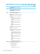
1 Product description HP Notebook PC; Intel 7th generation and Pentium/Celeron processors; non-touch models Category Description Product name HP Notebook PC Processor 7th generation Intel® Core™ processors Dis 7th M1-70 √ Dis 7th M1-30 √ UMA 7th Gen Core Dis Pent/ Celeron UMA Pent/ Celeron √ √ √ √ √ Model numbers: 15-ay100 – 15-ay199 √ √ Intel Core i7-7500U (2.7-GHz, turbo up to 3.5 GHz, 4MB L3 cache, 2133-MHz, dual, 15W) Intel Core i5-7200U (2.5-GHz, turbo up to 3.
Category Description Dis 7th M1-70 Dis 7th M1-30 UMA 7th Gen Core Dis Pent/ Celeron UMA Pent/ Celeron (1920×1080) display, slim 3.2 mm, eDP; typical brightness: 220 nits Memory 39.6-cm (15.6-in), full high-definition (FHD), white light-emitting diode (WLED), UVVA, AntiGlare (1920×1080) display, slim 3.
Category Description Dis 7th M1-70 Dis 7th M1-30 UMA 7th Gen Core Dis Pent/ Celeron UMA Pent/ Celeron SSHD configuration: ● 1-TB, 5400-rpm + 8GB NAND Hybrid hard drive, 9.5mm M.2 SATA-3 configurations: Optical drive ● 256 GB ● 128 GB Fixed, serial ATA, 9.5-mm tray load √ √ √ √ √ √ √ √ √ √ HP TrueVision HD IR: Full HD camera - activity LED, 2x IR, USB 2.
Category Description Dis 7th M1-70 Internal Card One M.2 slot for WLAN √ Ports HDMI version 1.4b supporting 1920 ×1080 @ 60Hz Dis 7th M1-30 UMA 7th Gen Core Dis Pent/ Celeron UMA Pent/ Celeron √ √ √ √ √ √ √ √ √ √ √ √ √ √ √ √ √ √ √ √ √ Hot Plug/unplug and auto detect for correct output to wide-aspect vs. standard aspect video RJ-45 (Ethernet) USB 3.0 (1 port; left side) USB 2.
Category Description ● AC adapter ● Battery ● Optical drive Dis 7th M1-70 Dis 7th M1-30 UMA 7th Gen Core Dis Pent/ Celeron UMA Pent/ Celeron HP Notebook PC; Intel 5th and 6th generation and Pentium/ Celeron processors; non-touch models Category Description Product name HP Notebook PC Processor 6th generation Intel® Core™ processors Dis 6th Gen Core M1-70 Dis 6th Gen Core M1-30 UMA 6th Gen Core Dis 5th Gen Core UMA 5th Gen Core Dis Pent/ Celeron UMA Pent/ Celeron √ √ √ √ √ √ √
Category Description Switchable discrete graphics Dis 6th Gen Core M1-70 Dis 6th Gen Core M1-30 UMA 6th Gen Core Dis 5th Gen Core UMA 5th Gen Core Dis Pent/ Celeron UMA Pent/ Celeron √ AMD Radeon™ R7 M440 R16M-M1-70 with up to 4096 MB of dedicated video memory (512Mx16 DDR3 x 4 PCs) AMD Radeon R5 M430 R16M-M1-30 with up to 2048 MB of dedicated video memory (256Mx16 DDR3 x 4 PCs) AMD Radeon R7 M440 R16M-M1-70 with up to 2048 MB of dedicated video memory (256Mx16 DDR3 x 4 PCs) √ √ √ AMD Radeon
Category Hard drives Description ● 12288-MB total system memory (8192×1) + (4096×1) [5th generation Intel Core models only] ● 8192-MB total system memory (8192×1) or (4096×2) ● 6144-MB total system memory (4096×1) + (2048×1) ● 4096-MB total system memory (4096×1) or (2048×2) ● 2048-MB total system memory (2048×1) Supports 6.35-cm (2.5-in) SATA hard drives in 9.5-mm (.37-in) and 7.0-mm (.
Category Description Dis 6th Gen Core M1-70 Dis 6th Gen Core M1-30 UMA 6th Gen Core Dis 5th Gen Core UMA 5th Gen Core Dis Pent/ Celeron UMA Pent/ Celeron Ethernet Integrated 10/100 network interface card (NIC) √ √ √ √ √ √ √ Wireless Network Integrated wireless options with single antenna (M.2/PCIe): √ √ √ √ √ √ √ √ √ √ √ √ √ √ √ √ √ √ √ √ √ Compatible with Miracast-certified devices Support for the following WLAN formats: ● Broadcom BCM43142 802.
Category Description Dis 6th Gen Core M1-70 Dis 6th Gen Core M1-30 45-W UMA 6th Gen Core Dis 5th Gen Core √ UMA 5th Gen Core Dis Pent/ Celeron UMA Pent/ Celeron √ √ 1 meter power cord √ √ √ √ √ √ √ Batteries √ √ √ √ √ √ √ 4-cell, 41-Whr Li-ion battery 3-cell, 31-Whr Li-ion battery Security fTPM 2.
Category Description Graphics Internal graphics UMA 7th Gen Core UMA Pentium/ Celeron √ Intel HD Graphics 620 (Intel 7th generation Core processors) Panel Intel HD Graphics 505 (Intel Pentium/Celeron processors) √ Intel HD Graphics 500 (Intel Pentium/Celeron processors) √ Support HD Decode, DX12, and HDMI √ √ 39.6-cm (15.6-in); Touch-on Panel (TOP); High-definition (HD), white lightemitting diode (WLED), SVA, BrightView (1366×768) display, slim 3.
Category Description UMA 7th Gen Core UMA Pentium/ Celeron √ √ DVD+/-RW Double-Layer SuperMulti Supports zero power optical drive Supports M-disc Supports configuration without optical drive Webcam/mic HP TrueVision HD: HD camera - activity LED, USB 2.0, BSI sensor, 720p by 30 frames per second HP Webcam– 640 x 480 by 24 frames per second Single digital microphone HP Noise Cancellation enabled Audio HP TrueVision HD IR: Full HD camera - activity LED, 2x IR LEDs, USB 2.
Category Description UMA 7th Gen Core UMA Pentium/ Celeron √ √ 45-W √ √ 1 meter power cord √ √ Batteries √ √ 3-cell, 31-Whr Li-ion battery √ √ fTPM 2.
Category Chipset Description UMA 6th Gen Core UMA 5th Gen Core Intel Pentium® N3710 (1.6-GHz, turbo up to 2.56 GHz, 2-MB L3 cache, 1600-MHz, quad, 6W) √ Intel Pentium® N3160 (1.6-GHz, turbo up to 2.
Category Hard drives Description ● 4096-MB total system memory (4096×1) ● 2048-MB total system memory (2048×1) Supports 6.35-cm (2.5-in) SATA hard drives in 9.5-mm (.37-in) and 7.0-mm (.28-in) thicknesses UMA 6th Gen Core UMA 5th Gen Core UMA Pentium/ Celeron √ √ √ √ √ √ √ √ √ √ √ √ Single hard drive configurations: ● 2-TB, 5400-rpm, 9.5-mm ● 1-TB, 5400-rpm, 9.5-mm ● 500-GB, 5400-rpm, 9.5-mm or 7.0-mm SSHD configuration: ● 1-TB, 5400-rpm + 8GB NAND Hybrid hard drive, 9.5mm M.
Category Description UMA 6th Gen Core UMA 5th Gen Core UMA Pentium/ Celeron Support SD/SDHC/SDXC Push-Pull Insertion/Removal Internal Card One M.2 slot for WLAN √ √ √ Ports HDMI version 1.4b supporting 1920 ×1080 @ 60Hz √ √ √ √ √ √ √ √ √ 45-W √ √ √ 1 meter power cord √ √ √ Batteries √ √ √ 3-cell, 31-Whr Li-ion battery √ √ √ fTPM 2.0 √ √ √ √ √ √ Hot Plug/unplug and auto detect for correct output to wide-aspect vs. standard aspect video RJ-45 (Ethernet) USB 3.
HP 250/256 G5 Notebook PC models Category Description DIS Skylake UMA Skylake DIS Broadwell UMA Broadwell UMA Braswell Product name HP 250 G5 Notebook PC √ √ √ √ √ √ √ Intel Core i5-6200U (2.3-GHz, turbo up to 2.8 GHz, 3-MB L3 cache, 1600-MHz, dual, 15W) √ √ Intel Core i3-6100U (2.3-GHz, 3-MB L3 cache, 1600MHz, dual, 15W) √ √ √ √ HP 256 G5 Notebook PC Processor 6th generation Intel® Core™ processors Intel Core i7-6500U (2.5-GHz, turbo up to 3.
Category Description ● 16384-MB total system memory (8192×2) ● 12288-MB total system memory (8192×1) + (4096×1) ● 8192-MB total system memory (8192×1) or (4096×2) ● 6144-MB total system memory (4096×1) + (2048×1) ● 4096-MB total system memory (4096×1) or (2048×2) ● 2048-MB total system memory (2048×1) DIS Skylake UMA Skylake Two non-customer-accessible/upgradable memory module slots DIS Broadwell UMA Broadwell √ √ UMA Braswell DDR3L-1600 dual channel support One non-customer-accessible
Category Description DIS Skylake UMA Skylake DIS Broadwell UMA Broadwell UMA Braswell √ √ √ √ √ √ √ √ √ √ DVD+/-RW Double-Layer SuperMulti Supports zero power optical drive Supports M-disc Supports configuration without optical drive Webcam/mic HP TrueVision HD: HD camera - activity LED, USB 2.
Category Description DIS Skylake UMA Skylake DIS Broadwell UMA Broadwell UMA Braswell √ √ √ √ √ √ √ √ √ Hot Plug/unplug and auto detect for correct output to wide-aspect vs. standard aspect video RJ-45 (Ethernet) USB 3.0 (1 port; left side) USB 2.
20 Chapter 1 Product description
2 External component identification Display Component Description (1) WLAN antennas* Send and receive wireless signals to communicate with wireless local area networks (WLANs). (2) Webcam light On: The webcam is in use. (3) Webcam Records video and captures photographs. Some products allow you to video conference and chat online using streaming video. To use a webcam (integrated camera): ▲ (4) Internal microphone Type camera in the taskbar search box, and then select Camera. Records sound.
Right side Component (1) Description Power light ● On: The computer is on. ● Blinking: The computer is in the Sleep state, a powersaving state. The computer shuts off power to the display and other unneeded components. ● Off: The computer is off or in Hibernation. Hibernation is a power-saving state that uses the least amount of power. Blinking white: The hard drive is being accessed.
Left side Component Description (1) Power connector Connects an AC adapter. (2) AC adapter and battery light ● White: The AC adapter is connected and the battery is fully charged. ● Blinking white: The AC adapter is disconnected and the battery has reached a low battery level. ● Amber: The AC adapter is connected and the battery is charging. ● Off: The battery is not charging. (3) Vent Enables airflow to cool internal components.
Component Description WARNING! To reduce the risk of personal injury, adjust the volume before putting on headphones, earbuds, or a headset. For additional safety information, refer to the Regulatory, Safety, and Environmental Notices. To access this guide: ▲ Select the Start button, select All apps, select HP Help and Support, and then select HP Documentation. NOTE: When a device is connected to the jack, the computer speakers are disabled.
Lights Component Description (1) Caps lock light On: Caps lock is on, which switches the key input to all capital letters. (2) Mute light ● Amber: Computer sound is off. ● Off: Computer sound is on.
Button Component (1) Description Power button ● When the computer is off, press the button to turn on the computer. ● When the computer is on, press the button briefly to initiate Sleep. ● When the computer is in the Sleep state, press the button briefly to exit Sleep. ● When the computer is in Hibernation, press the button briefly to exit Hibernation. CAUTION: Pressing and holding down the power button results in the loss of unsaved information.
Keys Component Description (1) esc key Displays system information when pressed in combination with the fn key. (2) fn key Executes frequently used system functions when pressed in combination with the esc key, action keys, or the spacebar. (3) Windows key Opens the Start menu. NOTE: Pressing the Windows key again will close the Start menu. (4) Action keys Execute frequently used system functions.
Using the action keys ● An action key performs an assigned function. ● The icon on each action key illustrates the function for that key. ● To use an action key, press and hold the key. Icon Description Opens Help and Support, which provides tutorials, information about the Windows operating system and your computer, answers to questions, and updates to your computer. Help and Support also provides automated troubleshooting tools and access to support.
Bottom Component Description (1) Battery lock Locks the battery in the battery bay. (2) Battery bay Holds the battery. (3) Battery release latch Releases the battery. (4) Speakers (2) Produce sound.
Labels The labels affixed to the computer provide information you may need when you troubleshoot system problems or travel internationally with the computer. IMPORTANT: Check the following locations for the labels described in this section: the bottom of the computer, inside the battery bay, under the service door, or on the back of the display. ● Service label—Provides important information to identify your computer.
3 Illustrated parts catalog Computer major components NOTE: HP continually improves and changes product parts. For complete and current information on supported parts for your computer, go to http://partsurfer.hp.com, select your country or region, and then follow the on-screen instructions.
Item Component Spare part number (1) Display assembly (touch or non-touch) not spared NOTE: For display assembly spare part information, see Display assembly subcomponents on page 38. (2) Top cover/keyboard NOTE: For a detailed list of keyboard country codes, see Top cover/keyboard on page 86.
Item Component Spare part number ● Intel Core i5-7200U processor and 4 GB of discrete graphics memory (R7M1-70) 903789-xx1 ● Intel Core i5-7200U processor and 4 GB of discrete graphics memory (R5M1-30) 903790-xx1 ● Intel Core i5-7200U processor and 2 GB of discrete graphics memory (R5M1-30) 903791-xx1 ● Intel Core i5-6200U processor and 4 GB of discrete graphics memory (R7M1-70) 854935-xx1 ● Intel Core i5-6200U processor and 4 GB of discrete graphics memory (R5M1-30) 858869-xx1 ● Intel Co
Item Component Spare part number ● Intel Core i3-5005U processor 854947-xx1 ● Intel Pentium N4200 processor 903799-xx1 ● Intel Pentium N3710 processor 854948-xx1 ● Intel Pentium N3450 processor 903801-xx1 ● Intel Pentium N3160 processor 854949-xx1 For use in HP 250/256 G5 Notebook PC models (discrete graphics memory; non-touch screen): ● Intel Core i5-7200U processor and 2 GB of discrete graphics memory 909212-xx1 ● Intel Core i5-6200U processor and 2 GB of discrete graphics memory 85
Item Component Spare part number Realtek RTL8188EE-VJ 802.11b/g/n 1x1 Wi-Fi Adapter 857334-855 Realtek RTL8723BE 802.11b/g/n 1x1 Wi-Fi + BT4.0 Combo Adapter 855106-855 Intel Dual Band Wireless-AC 3168 802.11 ac 1x1 WiFi + BT 4.
Item Component (20) Bottom cover Spare part number For use in HP Notebook PC models: ● Models with an optical drive 854999-001 ● Models without an optical drive 857281-001 For use in HP Notebook PC and HP 250/256 G5 Notebook PC models: (21) 36 ● Models with an optical drive (gray) 859513-001 ● Models without an optical drive (gray) 859514-001 ● Models with an optical drive (black) 906832-001 ● Models without an optical drive (black) 906833-001 Battery 4-cell, 41-Whr, 2.
Miscellaneous parts Component Spare part number HP Smart AC adapter (4.5 mm, non-PFC) 65-W, for use in HP Notebook PC and HP 250/256 G5 Notebook PC models 710412-001 65-W EM, for use in HP Notebook PC models 714635-850 65-W, for use in HP 250/256 G5 Notebook PC models 714657-001 45-W, for use in HP Notebook PC models 741553-850 45-W, for use in HP 250/256 G5 Notebook PC models 741727-001 Power cord (3-pin, black, 1.
Display assembly subcomponents Item Component Spare part number (1) Display bezel (includes Mylar screw covers) 855000-001 (2) Raw display panel (39.6-cm [15.
Item (5) Component Spare part number Touch screen 813944-001 Webcam/microphone module For use in HP Notebook PC models: ● HD 709372-030 ● VGA 766523-019 For use in HP Notebook PC and HP 250/256 G5 Notebook PC models: (6) (7) ● HD 861336-001 ● VGA 861337-001 Antenna (includes wireless antenna cable and transceiver) Single 854985-001 Dual 854986-001 Display enclosure: For use in Notebook PC models: ● Black models 854992-001 ● Turbo silver models 854987-001 ● Red models 854989-
Mass storage devices Item Component (1) Optical drive (DVD+/-RW Double-Layer SuperMulti; includes bracket and bezel) (2) (3) Spare part number For use in all models 858505-001 For use in HP 250/256 G5 Notebook PC models 908491-001 Solid-state drive, M.
Item Component Spare part number For use in HP Notebook PC and HP 250/256 G5 Notebook PC models: ● 1-TB, 5400-rpm, hybrid 8 GB SSD 731999-005 ● 1-TB, 5400-rpm, 2.5-in 778192-005 ● 1-TB, 5400-rpm, 2.
42 Chapter 3 Illustrated parts catalog
4 Removal and replacement procedures preliminary requirements Tools required You will need the following tools to complete the removal and replacement procedures: ● Flat-bladed screwdriver ● Magnetic screwdriver ● Phillips P0 and P1 screwdrivers Service considerations The following sections include some of the considerations that you must keep in mind during disassembly and assembly procedures.
Drive handling CAUTION: Drives are fragile components that must be handled with care. To prevent damage to the computer, damage to a drive, or loss of information, observe these precautions: Before removing or inserting a hard drive, shut down the computer. If you are unsure whether the computer is off or in Hibernation, turn the computer on, and then shut it down through the operating system. Before handling a drive, be sure that you are discharged of static electricity.
Typical electrostatic voltage levels Relative humidity Event 10% 40% 55% Walking across carpet 35,000 V 15,000 V 7,500 V Walking across vinyl floor 12,000 V 5,000 V 3,000 V Motions of bench worker 6,000 V 800 V 400 V Removing DIPS from plastic tube 2,000 V 700 V 400 V Removing DIPS from vinyl tray 11,500 V 4,000 V 2,000 V Removing DIPS from Styrofoam 14,500 V 5,000 V 3,500 V Removing bubble pack from PCB 26,500 V 20,000 V 7,000 V Packing PCBs in foam-lined box 21,000 V 11,0
Equipment guidelines Grounding equipment must include either a wrist strap or a foot strap at a grounded workstation. ● When seated, wear a wrist strap connected to a grounded system. Wrist straps are flexible straps with a minimum of one megohm ±10% resistance in the ground cords. To provide proper ground, wear a strap snugly against the skin at all times. On grounded mats with banana-plug connectors, use alligator clips to connect a wrist strap.
5 Removal and replacement procedures for Customer Self-Repair parts CAUTION: The Customer Self-Repair program is not available in all locations. Installing a part not supported by the Customer Self-Repair program may void your warranty. Check your warranty to determine if Customer Self-Repair is supported in your location. NOTE: HP continually improves and changes product parts. For complete and current information on supported parts for your computer, go to http://partsurfer.hp.
Battery Description Spare part number 4-cell, 41-Whr, 2.8-Ah Li-ion battery 807957-001 3-cell, 31-Whr, 2.8-Ah Li-ion battery 807956-001 Before disassembling the computer, follow these steps: 1. Shut down the computer. If you are unsure whether the computer is off or in Hibernation, turn the computer on, and then shut it down through the operating system. 2. Disconnect all external devices connected to the computer. 3.
Optical drive NOTE: Optical drive spare part kits include bracket and bezel. Description Spare part number DVD+/-RW Double-Layer SuperMulti Drive for use in all models 858505-001 DVD+/-RW Double-Layer SuperMulti Drive for use in HP 250/256 G5 Notebook PC models 908491-001 Before removing the optical drive, follow these steps: 1. Shut down the computer. If you are unsure whether the computer is off or in Hibernation, turn the computer on, and then shut it down through the operating system. 2.
3. If it is necessary to replace the bracket on the rear of the optical drive, remove the two Phillips PM2.0×2.5 screws (1) that secure the bracket to the drive, and then remove the bracket (2). Reverse this procedure to reassemble and install the optical drive.
6 Removal and replacement procedures for Authorized Service Provider parts CAUTION: Components described in this chapter should only be accessed by an authorized service provider. Accessing these parts can damage the computer or void the warranty. NOTE: HP continually improves and changes product parts. For complete and current information on supported parts for your computer, go to http://partsurfer.hp.com, select your country or region, and then follow the on-screen instructions.
Bottom cover Description Spare part number Bottom cover for use on HP Notebook models with an optical drive 854999-001 Bottom cover for use on HP Notebook models without an optical drive 857281-001 Bottom cover for use on HP 250/256 G5 Notebook PC models with an optical drive (gray) 859513-001 Bottom cover for use on HP 250/256 G5 Notebook PC models without an optical drive (gray) 859514-001 Bottom cover for use on HP 250/256 G5 Notebook PC models with an optical drive (black) 906832-001 Bottom
4. Start prying at the front of the computer and work around to the back to separate the bottom cover from computer. 5. Remove the bottom cover. Reverse this procedure to install the bottom cover.
WLAN module Description Spare part number Intel Dual Band Wireless-AC 3165 802.11 ac 1x1 WiFi + BT 4.2 Combo 806723-005 Realtek RTL8188EE-VJ 802.11b/g/n 1x1 Wi-Fi Adapter 857334-855 Realtek RTL8723BE 802.11b/g/n 1x1 Wi-Fi + BT4.0 Combo Adapter 855106-855 Intel Dual Band Wireless-AC 3168 802.11 ac 1x1 WiFi + BT 4.
3. Remove the WLAN module by pulling the module away from the slot at an angle (3). NOTE: If the WLAN antennas are not connected to the terminals on the WLAN module, the protective sleeves must be installed on the antenna connectors, as shown in the following illustration. Reverse this procedure to install the WLAN module.
Memory module Description Spare part number Memory module (PC3L, 12800, 1600-MHz) For use in models with 5th generation Intel Core processors, Intel Pentium processors, and Intel Celeron processors: 8-GB 693374-005 4-GB 691740-005 2-GB 691739-005 Memory module (PC4, 17000, 2133-MHz) For use in models with 6th and 7th generation Intel Core processors: 8-GB 820570-005 4-GB 820569-005 2-GB 851379-005 Before removing a memory module, follow these steps: 1. Shut down the computer.
2. Remove the memory module (2) by pulling it away from the slot at an angle. Reverse this procedure to install a memory module.
Optical drive board Description Spare part number Optical drive board (includes cable) 855007-001 Before removing the optical drive board, follow these steps: 1. Shut down the computer. If you are unsure whether the computer is off or in Hibernation, turn the computer on, and then shut it down through the operating system. 2. Disconnect all external devices connected to the computer. 3.
Speakers Description Spare part number Speakers (includes left and right speakers and cable) 813965-001 Before removing the speakers, follow these steps: 1. Shut down the computer. If you are unsure whether the computer is off or in Hibernation, turn the computer on, and then shut it down through the operating system. 2. Disconnect all external devices connected to the computer. 3.
Hard drive NOTE: The hard drive spare part kit does not include the hard drive bracket, cable, or connector board. Description Spare part number Hard drive for use in HP Notebook PC models: 2-TB, 5400-rpm, hybrid 8 GB SSD, 9.5 mm 801808-005 Hard drive for use in HP Notebook PC and HP 250/256 G5 Notebook PC models: 1-TB, 5400-rpm, hybrid 8 GB SSD 731999-005 1-TB, 5400-rpm, 2.5-in 778192-005 1-TB, 5400-rpm, 2.
3. Lift the hard drive assembly from the computer (3). 4. To remove the hard drive connector board, pull the connector away from the drive to remove it (1). 5. To remove the hard drive cable from the connector board, disconnect the cable from the connector on the board and remove it (2). 6. To remove the hard drive brackets, remove the two Phillips PM3.0×3.0 screws (1) that secure each bracket to the hard drive.
7. Remove the hard drive brackets from the hard drive (2). Reverse this procedure to reassemble and install the hard drive.
RTC battery Description Spare part number RTC battery 760828-001 Before removing the RTC battery, follow these steps: 1. Shut down the computer. If you are unsure whether the computer is off or in Hibernation, turn the computer on, and then shut it down through the operating system. 2. Disconnect all external devices connected to the computer. 3. Disconnect the power from the computer by first unplugging the power cord from the AC outlet and then unplugging the AC adapter from the computer. 4.
USB board Description Spare part number USB board (includes cable) 855010-001 Before removing the USB board, follow these steps: 1. Shut down the computer. If you are unsure whether the computer is off or in Hibernation, turn the computer on, and then shut it down through the operating system. 2. Disconnect all external devices connected to the computer. 3.
Solid-state drive (SSD) Description Spare part number Solid-state drive, 256-GB, M.2 865902-002 Solid-state drive, 128-GB, M.2, for use in HP Notebook PC models 827560-021 Solid-state drive, 128-GB, M.2, for use in HP 250/256 G5 Notebook PC models 861334-001 Solid-state drive, 256-GB, M.2, for use in HP 250/256 G5 Notebook PC models 861335-001 Before removing the solid-state drive, follow these steps: 1. Shut down the computer.
Solid-state drive board Description Spare part number Solid-state drive board (includes cable) 850946-001 Before removing the solid-state drive board, follow these steps: 1. Shut down the computer. If you are unsure whether the computer is off or in Hibernation, turn the computer on, and then shut it down through the operating system. 2. Disconnect all external devices connected to the computer. 3.
Heat sink assembly NOTE: The heat sink assembly spare part kit includes replacement thermal materials.
3. Remove the heat sink assembly from the system board (2). NOTE: Heat sink appearance may vary. Discrete graphics UMA graphics ● 68 Discrete graphics Thermal paste is used on the processor and associated heat sink area (1)(2), as well as the graphics chip and associated heat sink area (3)(4).
● UMA graphics Thermal paste is used on the heat sink (1) and the processor (2). Reverse this procedure to reassemble and install the heat sink assembly.
Fan Description Spare part number Fan 813946-001 NOTE: To properly ventilate the computer, allow at least 7.6 cm (3.0 in) of clearance on the left side of the computer. The computer uses an electric fan for ventilation. The fan is controlled by a temperature sensor and is designed to turn on automatically when high temperature conditions exist.
4. Remove the fan from the computer (3). Reverse this procedure to install the fan.
TouchPad button board Description Spare part number TouchPad button board (includes bracket and cables) 855011-001 Before removing the TouchPad button board, follow these steps: 1. Shut down the computer. If you are unsure whether the computer is off or in Hibernation, turn the computer on, and then shut it down through the operating system. 2. Disconnect all external devices connected to the computer. 3.
System board NOTE: The system board spare part kit includes replacement thermal materials.
Description Spare part number ● Intel Pentium N4200 processor 903798-xx1 ● Intel Pentium N3710 processor 854943-xx1 ● Intel Pentium N3710 processor, ESD 860062-xx1 ● Intel Pentium N3350 processor 903802-xx1 ● Intel Celeron N3060 processor 854944-xx1 For use in HP Notebook models (UMA graphics memory; touch screen):: ● Intel Core i7-6500U processor 909166-xx1 ● Intel Core i5-7200U processor 903793-xx1 ● Intel Core i5-6200U processor 854945-xx1 ● Intel Core i3-7100U processor 90379
1. Shut down the computer. If you are unsure whether the computer is off or in Hibernation, turn the computer on, and then shut it down through the operating system. 2. Disconnect all external devices connected to the computer. 3. Disconnect the power from the computer by first unplugging the power cord from the AC outlet and then unplugging the AC adapter from the computer. 4. Remove the battery (see Battery on page 48). 5. Remove the optical drive (see Optical drive on page 49), if installed. 6.
3. Lift the system board out of the computer (2). Reverse this procedure to install the system board.
Display assembly This section describes removing the display assembly and disassembling display subcomponents. You must remove the display from the computer to disassemble display subcomponents. Description Spare part number Raw display panel (39.6-cm [15.
Description Spare part number Silver models 905913-001 Hinges (left and right) 855006-001 Webcam/microphone module for use in HP Notebook PC models: HD 709372-030 VGA 766523-019 Webcam/microphone for use in HP Notebook PC and HP 250/256 G5 Notebook PC models: HD 861336-001 VGA 861337-001 Before removing the display assembly, follow these steps: 1. Shut down the computer.
4. Remove the four Phillips PM2.5×6.5 screws (1) (two from each hinge) and one broadhead Phillips PM2.0×2.0 screw (2) (on the left hinge) that secures the display assembly to the computer. 5. Separate the display from the computer (3). If it is necessary to replace any of the display assembly subcomponents: 1. To remove the display bezel: a.
2. 3. 80 To remove the webcam/microphone module: a. Position the display assembly with the top edge toward you. b. Disconnect the cable (1) from the module. c. Remove the webcam/microphone module (2). (The module is attached to the display enclosure with double-sided tape.) To remove the display panel: a. Remove the four Phillips PM2.0×3.0 screws that secure the display panel to the enclosure. b.
d. 4. Remove the display panel from the computer. To remove the display hinges: a. For each hinge, remove the two Phillips PM2.5×3.5 screws (1) and the two broadhead Phillips PM2.5×2.5 screws (2) that secure each hinge to the display enclosure. b. Remove the display hinges (3).
82 5. To remove the wireless antenna cables and transceivers, release the wireless antenna cables from the clips built into the display enclosure (1), and then remove the cables (2). 6. To remove the display/webcam cable, remove the cable from the clips built into the display enclosure (1), and then remove the cable from the display enclosure (2). 7.
8. Use the following image to determine proper cable routing for the display cable and the wireless antennas. (1): Display hinge (2): Display cable routing path (3): Antenna cable routing path Reverse this procedure to reassemble and install the display assembly.
Power connector cable Description Spare part number Power connector cable 813945-011 Before removing the power connector cable, follow these steps: 1. Shut down the computer. If you are unsure whether the computer is off or in Hibernation, turn the computer on, and then shut it down through the operating system. 2. Disconnect all external devices connected to the computer. 3.
Power button board Description Spare part number Power button board (includes cable) 855012-001 Before removing the power button board, follow these steps: 1. Shut down the computer. If you are unsure whether the computer is off or in Hibernation, turn the computer on, and then shut it down through the operating system. 2. Disconnect all external devices connected to the computer. 3.
Top cover/keyboard The top cover/keyboard spare part remains after all other spare parts have been removed. The top cover/keyboard spare part kit includes the keyboard, keyboard cable and the keyboard backlight cable. In this section, the first table provides the main spare part number for the keyboard. The second table provides the country codes. NOTE: All top cover/keyboard spare part kits include TouchPad.
For use in country or region Spare part number For use in country or region Spare part number For use in country or region Spare part number France -051 Romania -271 United Kingdom -031 Germany -041 Russia -251 United States -001 Component replacement procedures 87
88 Chapter 6 Removal and replacement procedures for Authorized Service Provider parts
7 Using Setup Utility (BIOS) in Windows 7 Setup Utility, or Basic Input/Output System (BIOS), controls communication between all the input and output devices on the system (such as disk drives, display, keyboard, mouse, and printer). Setup Utility (BIOS) includes settings for the types of devices installed, the startup sequence of the computer, and the amount of system and extended memory.
1. Select Start, type hp support assistant, and then select the HP Support Assistant program. 2. Follow the on-screen instructions to identify your computer and access the BIOS update you want to download. 3. At the download area, follow these steps: a. Identify the BIOS update that is later than the BIOS version currently installed on your computer. If the update is more recent than your BIOS version, make a note of the date, name, or other identifier.
8 Using Setup Utility (BIOS) in Windows 10 Setup Utility, or Basic Input/Output System (BIOS), controls communication between all the input and output devices on the system (such as disk drives, display, keyboard, mouse, and printer). Setup Utility (BIOS) includes settings for the types of devices installed, the startup sequence of the computer, and the amount of system and extended memory.
Downloading a BIOS update CAUTION: To reduce the risk of damage to the computer or an unsuccessful installation, download and install a BIOS update only when the computer is connected to reliable external power using the AC adapter. Do not download or install a BIOS update while the computer is running on battery power, docked in an optional docking device, or connected to an optional power source.
9 Backing up, restoring, and recovering in Windows 7 Your computer includes tools provided by the operating system and HP to help you safeguard your information and retrieve it if ever needed. Creating backups 1. Use HP Recovery Manager to create recovery media immediately after you set up the working computer. 2. As you add hardware and software programs, create system restore points. 3.
Creating the recovery media 1. Select Start and type recovery in the search field. Select HP Recovery Manager from the list. Allow the action to continue, if prompted. 2. Click Recovery Media Creation. 3. Follow the on-screen instructions to continue. To recover, see Recovering the original system using HP Recovery Manager on page 96. Creating system restore points A system restore point is a snapshot of certain hard drive contents saved by Windows System Restore at a specific time.
Tips for a successful backup ● Number backup discs before inserting them into the optical drive. ● Store personal files in the Documents, Music, Pictures, and Videos libraries, and back up these folders periodically. ● Save customized settings in a window, toolbar, or menu bar by taking a screen shot of your settings. The screen shot can be a time-saver if you have to re-enter your preferences. To create a screen shot: 1. Display the screen you want to save. 2.
Restore and recovery Restoring to a previous system restore point Sometimes installing a software program causes your computer or Windows to behave unpredictably. Usually uninstalling the software fixes the problems. If uninstalling does not fix the problems, you can restore the computer to a previous system restore point (created at an earlier date and time). To restore to a previous system restore point, when the computer was running correctly: 1.
● If the recovery media do not work, you can obtain recovery discs for your system from the HP website. ● The Minimized Image Recovery option is recommended for advanced users only. All hardware-related drivers and software are re-installed, but other software applications are not. Do not interrupt the process until it is complete, otherwise the recovery will fail.
98 1. Insert the flash drive into a USB port. 2. Restart the computer. 3. Press esc while the computer is restarting, and then press f9 for boot options. 4. Select the flash drive from the boot options window.
10 Backing up, restoring, and recovering in Windows 10 This chapter provides information about the following processes. The information in the chapter is standard procedure for most products. ● Creating recovery media and backups ● Restoring and recovering your system For additional information, refer to the HP support assistant app. ▲ Type support in the taskbar search box, and then select the HP Support Assistant app. ‒ or – Click the question mark icon in the taskbar.
You can use Windows tools to create system restore points and create backups of personal information, see Using Windows tools on page 100. ● If your computer does list the Recovery partition and the Windows partition, you can use HP Recovery Manager to create recovery media after you successfully set up the computer. HP Recovery media can be used to perform system recovery if the hard drive becomes corrupted.
Restore and recovery There are several options for recovering your system. Choose the method that best matches your situation and level of expertise: IMPORTANT: ● Windows offers several options for restoring from backup, refreshing the computer, and resetting the computer to its original state. For more information see the Get started app. ▲ ● Not all methods are available on all products. Select the Start button, and then select the Get started app.
website. Go to http://www.hp.com/support, select your country or region, and follow the on-screen instructions. IMPORTANT: HP Recovery Manager does not automatically provide backups of your personal data. Before beginning recovery, back up any personal data you want to retain. Using HP Recovery media, you can choose from one of the following recovery options: NOTE: Only the options available for your computer display when you start the recovery process.
Changing the computer boot order If your computer does not restart in HP Recovery Manager, you can change the computer boot order, which is the order of devices listed in BIOS where the computer looks for startup information. You can change the selection to an optical drive or a USB flash drive. To change the boot order: IMPORTANT: For a tablet with a detachable keyboard, connect the keyboard to the keyboard dock before beginning these steps. 1. Insert the HP Recovery media. 2.
104 Chapter 10 Backing up, restoring, and recovering in Windows 10
11 Using HP PC Hardware Diagnostics (UEFI) HP PC Hardware Diagnostics is a Unified Extensible Firmware Interface (UEFI) that allows you to run diagnostic tests to determine whether the computer hardware is functioning properly. The tool runs outside the operating system so that it can isolate hardware failures from issues that are caused by the operating system or other software components.
3. Enter the product name or number. – or – Select Identify now to let HP automatically detect your product. 4. Select your computer, and then select your operating system. 5. In the Diagnostic section, follow the on-screen instructions to select and download the UEFI version you want.
12 Specifications Computer specifications Metric U.S. Depth 254.6 mm 10.02 in Width 384.3 mm 15.13 in Height 24.3 mm 0.96 in 1994 g 4.40 lb 2040 g 4.50 lb Dimensions (touch models) Weight 3 cell battery 4 cell battery Input power Operating voltage and current 19.5 V dc @ 3.33 A – 65 W 19.5 V dc @ 2.
39.6-cm (15.6-in) display specifications Metric U.S. Active diagonal size 39.6-cm 15.6-in Resolution 1366x768 (HD) 1920x1080 (FHD) Surface treatment BrightView Brightness 200 nits (touch) 220 nits (non-touch) Viewing angle SVA Backlight WLED Graphics adapter eDP Thickness 3.2 mm (touch) 3.8 mm (non-touch) Hard drive specifications, hybrid drives 1000-GB*, 8 GB NAND hybrid SSD Dimensions Height 5 mm Length 100.2 mm Width 69.9 mm Weight 70.0 g Form Factor 2.
Hard drive specifications 2-TB* 1-TB* 500-GB* Height 9.5 mm 9.5 mm 7.0 mm or 9.5 mm Length 100.4 mm 100.4 mm 100.6 mm Width 69.9 mm 69.9 mm 70.1 mm Weight 130.0 g 107.0 g 92.0 g Interface type SATA SATA SATA Synchronous (maximum) 300 MB/sec 300 MB/sec 300 MB/sec Security ATA security ATA security ATA security Single track 2.0 ms 2.
M.2 solid-state drive specifications 128-GB* 256-GB* Height 1 mm 1 mm Length 50.8 mm 50.8 mm Width 28.9 mm 28.9 mm Weight < 10 g < 10 g Interface type ATA-7 ATA-7 Sequential Read Up to 520 MB/s Up to 540 MB/s Random Read Up to 60K IOPs Up to 85K IOPs Sequential Write Up to 160 MB/s Up to 280 MB/s Random Write Up to 34K IOPs Up to 67K IOPs Ready time, Maximum (to not busy) 1.0 s 1.0 s Logical 0.1 ms 0.
DVD±RW SuperMulti DL Drive specifications Component Value Applicable disc Read: Write: CD-DA, CD+(E)G, CD-MIDI, CD-TEXT, CD-ROM, CDROM XA, MIXED MODE CD, CD-I, CD-I Bridge (PhotoCD, Video CD), Multisession CD (Photo-CD, CDEXTRA, Portfolio, CD-R, CD-RW), CD-R, CD-RW, DVD-ROM (DVD-5, DVD-9, DVD-10, DVD-18), DVDR, DVD-RW, DVD+R, DVD+RW, DVD-RAM CD-R and CD-RW Center hole diameter DVD+R, DVD+RW, DVD-R, DVD-RW, DVD-RAM 1.5 cm (0.59 in) Disc diameter Standard disc 12 cm (4.72 in) Mini disc 8 cm (3.
112 Chapter 12 Specifications
13 Statement of memory volatility The purpose of this chapter is to provide general information regarding nonvolatile memory in HP Business PCs. This chapter also provides general instructions for restoring nonvolatile memory that can contain personal data after the system has been powered off and the hard drive has been removed. HP Business PC products that use Intel®-based or AMD®-based system boards contain volatile DDR memory.
g. If a DriveLock password is set, select the Security menu, and scroll down to Hard Drive Utilities under the Utilities menu. Select Hard Drive Utilities, select DriveLock, then uncheck the checkbox for DriveLock password on restart. Select OK to proceed. h. Select the Main menu, and then select Reset BIOS Security to factory default. Click Yes at the warning message. The computer will reboot. i.
NOTE: If the system has a BIOS administrator password, enter the password at the prompt. 2. a. Select Main, select Restore Defaults, and then select Yes to load defaults. b. Select the Security menu, select Restore Security Level Defaults, and then select Yes to restore security level defaults. c. If an asset or ownership tag is set, select the Security menu and scroll down to the Utilities menu. Select System IDs, and then select Asset Tracking Number.
NOTE: The amount of time it takes for Disk Sanitizer to run can take several hours. Plug the computer into an AC outlet before starting. a. Turn on or restart the computer, and then press esc while the "Press the ESC key for Startup Menu" message is displayed at the bottom of the screen. b. Select the Security menu and scroll down to the Utilities menu. c. Select Hard Drive Tools. d.
Nonvolatile memory usage Nonvolatile Memory Type HP Sure Start flash (select models only) Amount (Size) Does this memory store customer data? Does this memory retain data when power is removed? 2 MBytes No Yes What is the purpose of this memory? Provides protected backup of critical System BIOS code, EC firmware, and critical PC configuration data for select platforms that support HP Sure Start.
Nonvolatile Memory Type Amount (Size) Does this memory store customer data? Does this memory retain data when power is removed? What is the purpose of this memory? How is data input into this memory? How is this memory write-protected? the on-screen instructions. Intel Management 1.5 MBytes or 5 Engine Firmware MBytes (present in only specific ZBook and EliteBook models. For more information, go to http://www.hp.com/ support. Select Find your product, and then follow the onscreen instructions.
Questions and answers 1. How can the BIOS settings be restored (returned to factory settings)? IMPORTANT: Restore defaults does not securely erase any data on your hard drive. See question and answer 6 for steps to securely erase data. Restore defaults does not reset the Custom Secure Boot keys. See question and answer 7 for information about resetting the keys. 2. a.
IMPORTANT: Resetting will result in the loss of information. These steps will not reset Custom Secure Boot Keys. See question and answer 7 for information about resetting the keys. 7. a. Turn on or restart the computer, and then press esc while the "Press the ESC key for Startup Menu" message is displayed at the bottom of the screen. b. Select Main, and then select Reset BIOS Security to Factory Default. c. Follow the on-screen instructions. d.
14 Power cord set requirements The wide-range input feature of the computer permits it to operate from any line voltage from 100 to 120 volts ac, or from 220 to 240 volts ac. The 3-conductor power cord set included with the computer meets the requirements for use in the country or region where the equipment is purchased. Power cord sets for use in other countries and regions must meet the requirements of the country or region where the computer is used.
Requirements for specific countries and regions Country/region Accredited agency Applicable note number Argentina IRAM 1 Australia SAA 1 Austria OVE 1 Belgium CEBEC 1 Brazil ABNT 1 Canada CSA 2 Chile IMQ 1 Denmark DEMKO 1 Finland FIMKO 1 France UTE 1 Germany VDE 1 India ISI 1 Israel SII 1 Italy IMQ 1 Japan JIS 3 The Netherlands KEMA 1 New Zealand SANZ 1 Norway NEMKO 1 The People's Republic of China CCC 4 Saudi Arabia SASO 7 Singapore PSB 1 So
Country/region Accredited agency Applicable note number 3. The appliance coupler, flexible cord, and wall plug must bear a “T” mark and registration number in accordance with the Japanese Dentori Law. The flexible cord must be Type VCTF, 3-conductor, 0.75mm2 or 1.25mm2 conductor size. The wall plug must be a two-pole grounding type with a Japanese Industrial Standard C8303 (7 A, 125 V ac) configuration. 4. The flexible cord must be Type RVV, 3-conductor, 0.75mm2 conductor size.
124 Chapter 14 Power cord set requirements
15 Recycling When a non-rechargeable or rechargeable battery has reached the end of its useful life, do not dispose of the battery in general household waste. Follow the local laws and regulations in your area for battery disposal. HP encourages customers to recycle used electronic hardware, HP original print cartridges, and rechargeable batteries. For more information about recycling programs, see the HP Web site at http://www.hp.com/recycle.
126 Chapter 15 Recycling
Index A AC adapter and battery 23 action keys 28 identifying 27 airplane mode key 28 antenna illustrated 39 antennas removing 82 audio, product description 3, 7, 11, 14, 18 audio-out (headphone)/audio-in (microphone) jack, identifying 23 B backups 93, 99 battery illustrated 36 removing 48 battery cover, identifying 29 battery lock, identifying 29 battery release latch 29 BIOS determining version 89, 91 downloading an update 89, 92 starting the Setup Utility 91 updating 89, 91 Bluetooth label 30 boot order c
heat sink assembly illustrated 35 removing 35, 67 hinges illustrated 38 removing 80, 81 HP PC Hardware Diagnostics (UEFI) using 105 HP Recovery Manager 96 correcting boot problems 103 starting 102 HP Recovery media creating 99 recovery 102 HP Recovery partition recovery 102 removing 103 HP Sure Start 120 I integrated numeric keypad, identifying 27 internal card product description 4, 8, 11, 15, 18 internal microphone, identifying 21 J jacks audio-out (headphone)/audio-in (microphone) 23 network 23 RJ-45 (ne
microphone 3, 7, 11, 14, 18 operating system 4, 9, 12, 15, 19 optical drive 3, 7, 10, 14, 17 pointing device 4, 8, 11, 15, 19 ports 4, 8, 11, 15, 18 power requirements 4, 8, 12, 15, 19 processor 1, 5, 9, 12, 16 product name 1, 5, 9, 12, 16 security 4, 9, 12, 15, 19 serviceability 4, 9, 12, 15, 19 video 3, 7, 11, 14, 18 wireless 3, 8, 11, 14, 18 product name 1, 5, 9, 12, 16 product name and number, computer 30 R recover options 101 recovering from the recovery discs 97 recovering the original system 96 recov
wireless antenna illustrated 39 wireless antennas removing 82 wireless certification label 30 wireless, product description 3, 8, 11, 14, 18 WLAN antennas, identifying 21 WLAN device 30 WLAN label 30 WLAN module illustrated 34 removing 54 workstation guidelines 45 130 Index