
HP Notebook PC (Intel) * Models: 15-ay000 - 15-ay099 HP 250 G5 Notebook PC HP 256 G5 Notebook PC - Maintenance and Service Guide
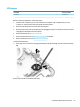
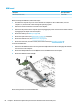


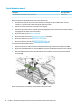
Table Of Contents
- Product description
- HP Notebook PC; Intel 7th generation and Pentium/Celeron processors; non-touch models
- HP Notebook PC; Intel 5th and 6th generation and Pentium/Celeron processors; non-touch models
- HP Notebook PC; Intel 7th generation Core and Pentium/Celeron processors; touch models
- HP Notebook PC; Intel 5th and 6th generation and Pentium/Celeron processors; touch models
- HP 250/256 G5 Notebook PC models
- External component identification
- Illustrated parts catalog
- Removal and replacement procedures preliminary requirements
- Removal and replacement procedures for Customer Self-Repair parts
- Removal and replacement procedures for Authorized Service Provider parts
- Using Setup Utility (BIOS) in Windows 7
- Using Setup Utility (BIOS) in Windows 10
- Backing up, restoring, and recovering in Windows 7
- Backing up, restoring, and recovering in Windows 10
- Using HP PC Hardware Diagnostics (UEFI)
- Specifications
- Statement of memory volatility
- Power cord set requirements
- Recycling
- Index
Solid-state drive (SSD)
Description Spare part number
Solid-state drive, 256-GB, M.2 865902-002
Solid-state drive, 128-GB, M.2, for use in HP Notebook PC models 827560-021
Solid-state drive, 128-GB, M.2, for use in HP 250/256 G5 Notebook PC models 861334-001
Solid-state drive, 256-GB, M.2, for use in HP 250/256 G5 Notebook PC models 861335-001
Before removing the solid-state drive, follow these steps:
1. Shut down the computer. If you are unsure whether the computer is o or in Hibernation, turn the
computer on, and then shut it down through the operating system.
2. Disconnect all external devices connected to the computer.
3. Disconnect the power from the computer by rst unplugging the power cord from the AC outlet and then
unplugging the AC adapter from the computer.
4. Remove the battery (see Battery on page 48).
5. Remove the optical drive (see Optical drive on page 49), if installed.
6. Remove the bottom cover (see Bottom cover on page 52).
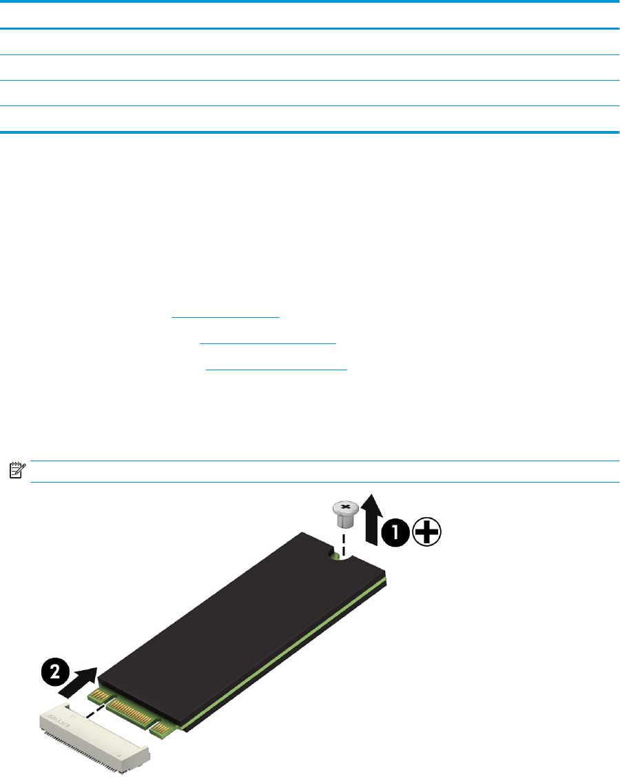
Remove the solid-state drive:
1. Remove the Phillips PM2.0×2.0 screw (1) that secures the drive to the system board.
2. Remove the drive (2) by pulling it away from the connector.
NOTE: Solid-state drives are designed with notches to prevent incorrect insertion.
Reverse this procedure to reassemble and install the solid-state drive.
Component replacement procedures 65