Maintenance and Service Guide HP ProDesk 680 G3 MT and HP ProDesk 600 G3 MT
© Copyright 2017 HP Development Company, L.P. Product notice AMD is a trademark of Advanced Micro Devices, Inc. Bluetooth is a trademark owned by its proprietor and used by HP Inc. under license. Intel, Core, and Celeron are trademarks of Intel Corporation in the U.S. and other countries. Microsoft and Windows are either registered trademarks or trademarks of Microsoft Corporation in the United States and/or other countries. SD Logo is a trademark of its proprietor.
About This Book WARNING! Text set off in this manner indicates that failure to follow directions could result in bodily harm or loss of life. CAUTION: Text set off in this manner indicates that failure to follow directions could result in damage to equipment or loss of information. NOTE: Text set off in this manner provides important supplemental information.
iv About This Book
Table of contents 1 Product features ........................................................................................................................................... 1 Standard configuration features ........................................................................................................................... 1 Front panel components ........................................................................................................................................
4 Removal and replacement procedures ........................................................................................................... 20 Preparation for disassembly ............................................................................................................................... 20 Access panel ......................................................................................................................................................... 21 Dust filter .......................
Solving keyboard and mouse problems .............................................................................................................. 76 Solving hardware installation problems ............................................................................................................. 79 Solving network problems .................................................................................................................................. 80 Solving memory problems ...........................
System Recovery ............................................................................................................................. 109 System Recovery when Windows is responding .......................................................... 110 System Recovery when Windows is not responding .................................................... 110 System Recovery using recovery media (select models only) .....................................
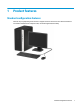
1 Product features Standard configuration features Features may vary depending on the model. For support assistance and to learn more about the hardware and software installed on the computer model, run the HP Support Assistant utility.
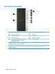
Front panel components (1) 5.25-inch drive bay (behind bezel) (6) USB 2.0 port with HP Sleep and Charge* (2) Slim optical drive (optional) (7) USB 2.0 port (3) Dual-state power button (8) USB 3.
Rear panel components Refer to the following images and tables for the rear components on vPro and non-vPro systems. vPro systems (1) Audio-in jack (6) Audio-out jack for power audio devices (2) DisplayPort monitor connectors (2) (7) RJ-45 (network) jack (3) Optional port (8) Optional serial port (4) USB 2.0 ports with Wake from S4/S5 (4) (9) Power cord connector (5) USB 3.x Ports (2) NOTE: If using a USB keyboard, HP recommends connecting the keyboard to one of the USB 2.
Non-vPro systems (1) Audio-in jack (6) Audio-out jack for power audio devices (2) DisplayPort monitor connectors (2) (7) RJ-45 (network) jack (3) Optional port (8) Optional serial port (4) USB 2.0 ports with Wake from S4/S5 (4) (9) Power cord connector (5) USB 3.x Ports (2) NOTE: If using a USB keyboard, HP recommends connecting the keyboard to one of the USB 2.0 ports with the Wake from S4/ S5 feature.
2 Illustrated parts catalog Serial number location Each computer has a unique serial number and a product ID number that are located on the exterior of the computer. Keep these numbers available for use when contacting support for assistance.
Description Equipped with a non-Windows operating system and PCI slots Equipped with NetC operating system and PCI slots in the People’s Republic of China For use on HP ProDesk 600 G3 MT computer models: Equipped with the Windows 10 operating system Equipped with a non-Windows operating system Equipped with NetC operating system in the People’s Republic of China Processors: Intel Core i7-7700 3.60-GHz processor (8.0-MB L3 cache, quad core, 65-W) Intel Core i7-6700 3.40-GHz processor (8.
Description DVD-ROM Drive, 9.5-mm, slim DVD±RW SuperMulti Drive, 9.5-mm, slim Optical drive long bezel blank, 9.5-mm, slim Optical drive latch, 9.5-mm, slim Removable DP27 Kit, 9.5-mm, slim Networking: Intel 7265.NGWG.NV ac 2×2 + Bluetooth 4.0 LE PCIe + USB NGFF 2230 non-vPro Combo Adapter Intel ac 2×2 + Bluetooth 4.2 M.2 PCI-e + USB non-vPro Combo Adapter Intel ac 2×2 + Bluetooth 4.2 M.
Description 1-TB, 2280 M.2, Non-Volatile Memory express (NVMe) solid-state drive with secure seal (SS) and triple-level cell (TLC) 512-GB, 2280 M.2, NVMe solid-state drive with SS and TLC 512-GB, 2280 M.2, NVMe solid-state drive with SS 512-GB solid-state drive with Federal Information Processing Standard (FIPS) 140-2 security 512-GB, self-encrypted solid-state drive with OPAL2 and TLC 256-GB, SATA-3 solid-state drive 256-GB, 2280 M.2, NVMe solid-state drive with SS and TLC 256-GB, 2280 M.
Description HP DisplayPort–to–VGA adapter HP USB Type-C–to–DisplayPort adapter HP USB Type-C–to–USB 3.0 adapter Cables: DisplayPort cable (1.
Description HP PS/2 slim Windows 8 keyboard: For use in Belgium For use in BHCSY For use in Bulgaria For use in Canada For use in the Czech Republic and Slovakia For use in Denmark For use in France For use in Germany For use in Greece For use in Hungary For use in India For use in INT For use in Israel For use in Italy For use in Japan For use in Latin America For use in North Africa For use in Norway For use in the People’s Republic of China For use in Portugal For use in Romania For use in Russia For use
Description For use in Belgium For use in BHCSY For use in Bulgaria For use in Canada For use in the Czech Republic and Slovakia For use in Denmark For use in France For use in Germany For use in Greece For use in Hungary For use in India For use in INT For use in Israel For use in Italy For use in Japan For use in Latin America For use in North Africa For use in Norway For use in the People’s Republic of China For use in Portugal For use in Romania For use in Russia For use in Saudi Arabia For use in South
Description For use in Japan For use in Latin America For use in the People’s Republic of China For use in the South Korea For use in Taiwan For use in Thailand For use in the United States HP Antimicrobial slim business keyboard for use in the People’s Republic of China HP USB slim business keyboard in grey finish for use in Germany USB PS/2 washable Windows 8 keyboard (BFR-PVC): For use in Brazil For use in Canada For use in Latin America For use in the United States Lock: HP Business PC Security Lock Kit
3 Routine care, SATA drive guidelines, and disassembly preparation This chapter provides general service information for the computer. Adherence to the procedures and precautions described in this chapter is essential for proper service. CAUTION: When the computer is plugged into an AC power source, voltage is always applied to the system board. The power cord must be disconnected from the power source before opening the computer to prevent system board or component damage.
Preventing electrostatic damage to equipment Many electronic components are sensitive to ESD. Circuitry design and structure determine the degree of sensitivity. The following packaging and grounding precautions are necessary to prevent damage to electric components and accessories. ● To avoid hand contact, transport products in static-safe containers such as tubes, bags, or boxes. ● Protect all electrostatic-sensitive parts and assemblies with conductive or approved containers or packaging.
Recommended materials and equipment The following grounding equipment is recommended to prevent electrostatic damage: ● Antistatic tape ● Antistatic smocks, aprons, or sleeve protectors ● Conductive bins and other assembly or soldering aids ● Conductive foam ● Conductive tabletop workstations with ground cords of one-megohm +/- 10% resistance ● Static-dissipative table or floor mats with hard ties to ground ● Field service kits ● Static awareness labels ● Wrist straps and footwear straps pr
● Never cover the ventilation slots on the monitor with any type of material. ● Install or enable power management functions of the operating system or other software, including sleep states. Routine care General cleaning safety precautions 1. Never use solvents or flammable solutions to clean the computer. 2. Never immerse any parts in water or cleaning solutions; apply any liquids to a clean cloth and then use the cloth on the component. 3.
● If you want to remove a key, use a specially designed key puller to prevent damage to the keys. This tool is available through many electronics supply outlets. CAUTION: Never remove a wide, level key (like the space bar) from the keyboard. If these keys are improperly removed or installed, the keyboard may not function properly. ● Cleaning under a key may be done with a swab moistened with isopropyl alcohol and then squeezed out.
Cables and connectors Most cables used throughout the unit are flat, flexible cables. These cables must be handled with care to avoid damage. Apply only the tension required to seat or unseat the cables during insertion or removal from the connector. Handle cables by the connector whenever possible. In all cases, avoid bending or twisting the cables, and ensure that the cables are routed in such a way that they cannot be caught or snagged by parts being removed or replaced.
SATA hard drives Serial ATA Hard Drive Characteristics Number of pins/conductors in data cable 7/7 Number of pins in power cable 15 Maximum data cable length 39.37 in (100 cm) Data interface voltage differential 400-700 mV Drive voltages 3.3 V, 5 V, 12 V Jumpers for configuring drive N/A Data transfer rate 6.
4 Removal and replacement procedures Adherence to the procedures and precautions described in this chapter is essential for proper service. After completing all necessary removal and replacement procedures, run the Diagnostics utility to verify that all components operate properly. NOTE: Not all features listed in this guide are available on all computers. Preparation for disassembly WARNING! Voltage is always present on the system board when the computer is plugged into an active AC outlet.
Access panel 1. Prepare the computer for disassembly (see Preparation for disassembly on page 20). 2. Position the computer with the rear toward you. 3. Slide the access panel release latch (1) to the left. 4. Use the access panel release handle (2) to pull the access panel back. 5. Remove the access panel (3). Reverse this procedure to install the access panel.
Dust filter 1. Prepare the computer for disassembly (see Preparation for disassembly on page 20). 2. Remove the access panel (see Access panel on page 21). 3. Stand the computer upright with the front facing toward you. 4. Detach the dust filter from the front of the computer. Reverse this procedure to install the dust filter.
Front bezel 1. Prepare the computer for disassembly (see Preparation for disassembly on page 20). 2. Remove the access panel (see Access panel on page 21). 3. Position the computer in the horizontal mode with the front facing toward you. 4. Release the three tabs (1) on the top of the front bezel from the computer chassis. 5. Swing the top edge of the front bezel (2) away from the computer chassis. 6. Remove the front bezel. Reverse this procedure to install the front bezel.
Internal drive bezel 1. Prepare the computer for disassembly (see Preparation for disassembly on page 20). 2. Remove the access panel (see Access panel on page 21). 3. Remove the front bezel (see Front bezel on page 23). 4. Release the tab (1) on the left side of the internal drive bezel that attaches to the front bezel. 5. Remove the internal drive bezel (2). Reverse this procedure to install the internal drive bezel.
Speaker Follow these steps to remove the speaker: 1. Prepare the computer for disassembly (see Preparation for disassembly on page 20). 2. Remove the access panel (see Access panel on page 21). 3. Position the computer with the front panel toward you. 4. Disconnect the speaker cable (1) from the system board. 5. Remove the two Torx-15 M3.5×8.5 screws (2) that secure the speaker to the computer chassis. 6. Remove the speaker (3). Reverse this procedure to install the speaker.
Card reader module Follow these steps to remove the card reader module: 1. Prepare the computer for disassembly (see Preparation for disassembly on page 20). 2. Remove the access panel (see Access panel on page 21). 3. Position the computer with the front panel toward you. 4. Disconnect the card reader module cable (1) from the system board. 5. Remove the Torx-15 M3.5×8.5 screw (2) that secures the card reader module to the computer chassis. 6. Remove the card reader module (3).
Hood sensor module Follow these steps to remove the hood sensor module: 1. Prepare the computer for disassembly (see Preparation for disassembly on page 20). 2. Remove the access panel (see Access panel on page 21). 3. Position the computer with the rear panel toward you. 4. Disconnect the hood sensor module cable (1) from the system board. 5. Release the hood sensor module (2) from the retention clip built into the computer chassis. 6. Remove the hood sensor module.
Serial port module Follow these steps to remove the serial port module: 1. Prepare the computer for disassembly (see Preparation for disassembly on page 20). 2. Remove the access panel (see Access panel on page 21). 3. Position the computer with the rear panel toward you. 4. Disconnect the serial port module cable (1) from the system board. 5. Remove the two 3/16” screwlocks (2) that secure the serial port module to the computer chassis. 6. Remove the serial port module (3).
Fan Follow these steps to remove the speaker: 1. Prepare the computer for disassembly (see Preparation for disassembly on page 20). 2. Remove the access panel (see Access panel on page 21). 3. Position the computer with the rear panel toward you. 4. Disconnect the fan cable (1) from the system board. 5. Remove the three Phillips PM4.8×12.2 screws (2) that secure the fan to the computer chassis. 6. Remove the fan (3). Reverse this procedure to install the fan.
Hard drives Follow these steps to remove a 2.5-inch hard drive: 30 1. Prepare the computer for disassembly (see Preparation for disassembly on page 20). 2. Remove the access panel (see Access panel on page 21). 3. Disconnect the hard drive power cable (1) from the 2.5-inch hard drive. 4. Disconnect the hard drive data cable (2) from the 2.5-inch hard drive. 5. Release the retention clip (1) that secures the 2.5-inch hard drive to the drive cage. 6. Lift the left side of the 2.
7. Slide the 2.5-inch hard drive to the left as far as it will go, and then remove the 2.5-inch hard drive (3). Follow these steps to remove a 3.5-inch hard drive: 1. Prepare the computer for disassembly (see Preparation for disassembly on page 20). 2. Remove the access panel (see Access panel on page 21). 3. Position the computer with the rear panel toward you. 4. Disconnect the hard drive power cable (1) from the 3.5-inch hard drive. 5. Disconnect the hard drive data cable (2) from the 3.
6. Release the retention clip (1) that secures the 3.5-inch hard drive to the drive cage. 7. Lift the right side of the 3.5-inch hard drive (2) until it releases from the slots in the drive cage. 8. Slide the 3.5-inch hard drive to the right as far as it will go, and then remove the 3.5-inch hard drive (3). Reverse this procedure to install the hard drives.
Optical drives Follow these steps to remove a 5.25-inch size optical drive: 1. Prepare the computer for disassembly (see Preparation for disassembly on page 20). 2. Remove the access panel (see Access panel on page 21). 3. Disconnect the optical drive power cable (1) from the optical drive. 4. Disconnect the optical drive data cable (2) from the optical drive. 5. Press and hold the optical drive release latch (1) that secures the optical drive to the drive cage.
6. Slide the optical drive (2) out of the optical drive bay. Follow these steps to remove a slim optical drive: 34 1. Prepare the computer for disassembly (see Preparation for disassembly on page 20). 2. Remove the access panel (see Access panel on page 21). 3. Disconnect the optical drive data cable (1) from the optical drive. 4. Disconnect the optical drive power cable (2) from the optical drive. 5. Press on the optical drive release latch (1) that secures the optical drive to the drive cage.
6. Slide the optical drive (2) out of the optical drive bay. Reverse this procedure to install the optical drives.
Drive cage 1. Prepare the computer for disassembly (see Preparation for disassembly on page 20). 2. Remove the access panel (see Access panel on page 21). 3. Disconnect all cables to drives installed in the drive cage (see Hard drives on page 30 and Optical drives on page 33). 4. Lift the rear edge of the drive cage (1) to disengage the cage from the computer chassis. 5. Slide the drive cage (2) toward the rear panel. 6. Remove the drive cage (3).
Memory module The computer has three memory module sockets. CAUTION: You must disconnect the power cord and wait approximately 30 seconds for the power to drain before adding or removing memory modules. Regardless of the power-on state, voltage is always supplied to the memory modules as long as the computer is plugged into an active AC outlet. Adding or removing memory modules while voltage is present may cause irreparable damage to the memory modules or system board.
Expansion card The computer has two PCI Express x1 expansion sockets and two PCI Express x16 expansion sockets. NOTE: The PCI Express sockets support only low profile cards. You can install a PCI Express x1, x4, x8, or x16 expansion card in the PCI Express x16 sockets. For dual graphics card configurations, the first (primary) card must be installed in the PCI Express x16 sockets. To remove, replace, or add an expansion card: 1.
b. If you are installing an expansion card in a vacant PCI Express x1 socket, insert a flatblade screwdriver into the slots on the rear of expansion slot cover (1) and rock the slot cover back and forth to break it free from the chassis (2).
c. If you are installing an expansion card in a vacant PCI Express x16 socket, remove the appropriate expansion slot cover on the back of the chassis. Pull the slot cover straight up then away from the inside of the chassis. 7. Store the removed card in anti-static packaging. 8. If you are not installing a new expansion card, install an expansion slot cover to close the open slot.
Power supply Follow these steps to remove the power supply: 1. Prepare the computer for disassembly (see Preparation for disassembly on page 20). 2. Remove the access panel (see Access panel on page 21). 3. Remove the drive cage (see Drive cage on page 36). 4. Position the computer with the rear panel toward you. 5. Disconnect the power supply cables (1) from the three power supply cable connectors on the system board. 6.
Fan-sink NOTE: The fan-sink spare park kit includes replacement thermal material. Follow these steps to remove the fan-sink: 1. Prepare the computer for disassembly (see Preparation for disassembly on page 20). 2. Remove the access panel (see Access panel on page 21). 3. Remove the drive cage (see Drive cage on page 36). 4. Disconnect the fan-sink cable (1) from the system board. 5. Loosen the four slotted Torx-15 captive screws (2) that secure the fan-sink to the computer chassis.
Reverse this procedure to install the fan-sink.
Processor NOTE: The processor spare park kit includes replacement thermal material. Follow these steps to remove the processor: 1. Prepare the computer for disassembly (see Preparation for disassembly on page 20). 2. Remove the access panel (see Access panel on page 21). 3. Remove the drive cage (see Drive cage on page 36). 4. Remove the fan-sink (see Fan-sink on page 42). 5. Slide the processor release lever (1) to the right until it clears the locking clip. 6.
System board NOTE: The system board spare park kit includes replacement thermal material. Follow these steps to remove the system board: 1. Prepare the computer for disassembly (see Preparation for disassembly on page 20). 2. Remove the access panel (see Access panel on page 21), and then remove the following components: a. Drive cage (see Drive cage on page 36) b. Serial port module (see Serial port module on page 28) c.
4. Remove the eight Torx-15 M3.3×8.9 screws that secure the system board to the computer chassis. 5. Slide the system board (1) forward through the opening in the front of the computer chassis. 6. Swing the rear edge of the system board (2) up and forward until the components on the rear edge are clear of the rear panel. 7. Remove the system board (3) by sliding the rear edge up and back at an angle. Reverse this procedure to install the system board.
5 Computer Setup (F10) Utility Computer Setup (F10) Utilities Use Computer Setup (F10) Utility to do the following: ● Change settings from the defaults or restore the settings to default values. ● View the system configuration, including settings for processor, graphics, memory, audio, storage, communications, and input devices. ● Modify the boot order of bootable devices such as hard drives, optical drives, or USB flash media devices.
4. Use the arrow (left and right) keys to select the appropriate heading. Use the arrow (up and down) keys to select the option you want, then press Enter. To return to the Computer Setup Utilities menu, press Esc. 5. To apply and save changes, select Main > Save Changes and Exit. ● If you have made changes that you do not want applied, select Ignore Changes and Exit. ● To restore settings from the Advanced and Main menus to original values, select Apply Factory Defaults and Exit.
Computer Setup–Main NOTE: Support for specific Computer Setup options may vary depending on the hardware configuration. Table 5-1 Computer Setup—Main Option Description System Information Lists all information in following list if Advanced System Information is selected. Lists smaller subset if Basic System Information is selected.
Table 5-1 Computer Setup—Main (continued) Option Description ● Lock BIOS Version If this option is checked, the system is locked to the current BIOS version and updates are not allowed. ● BIOS Update Preferences Allows the administrator to select the source of network updates (www.hp.
Computer Setup—Security NOTE: Support for specific Computer Setup options may vary depending on the hardware configuration. Table 5-2 Computer Setup—Security Option Description Set up BIOS Administrator Password Lets you set and enable a BIOS administrator password, which includes the following privileges: ● Manage other BIOS users ● Full access to BIOS policy and settings ● Unlock the computer when other BIOS users fail the preboot authentication.
Table 5-2 Computer Setup—Security (continued) Option Description ● Data Recovery Policy Select ‘Automatic’ or ‘Manual’ to set data recovery policy. ‘Manual’ lets you select whether or not to execute recovery of a corrupted region if it is detected. Set Up BIOS Power-On Password Lets you set and enable a BIOS power-on password. The power-on password prompt appears after a power cycle or reboot. If the user does not enter the correct power-on password, the unit will not boot.
Table 5-2 Computer Setup—Security (continued) Option Description Default is ‘Unlock’. Cover Removal Sensor (Disabled/Notify user/Administrator password) Lets you disable the cover sensor or configure what action is taken if the computer cover was removed. Default is ‘Disabled’. NOTE: Notify user alerts the user with a POST error on the first boot after the sensor detects removal of the cover.
Table 5-3 Computer Setup—Advanced (for advanced users) (continued) Option Heading Default is enabled. Specify the order in which UEFI boot sources (such as a internal hard drive, USB hard drive, USB optical drive, or internal optical drive) are checked for a bootable operating system image. UEFI boot sources always have precedence over legacy boot sources.
Table 5-3 Computer Setup—Advanced (for advanced users) (continued) Option Heading Controls the virtualization features of the processor. Changing this setting requires turning the computer off and then back on. Default is disabled. Virtualization Technology (VTx) (Intel only) Controls the virtualization features of the processor. Changing this setting requires turning the computer off and then back on. Default is disabled.
Table 5-3 Computer Setup—Advanced (for advanced users) (continued) Option Heading Select to show the device in the operating system. Default is enabled. Touch Panel Clear to disable the display panel touch feature. Default is enabled.
Table 5-3 Computer Setup—Advanced (for advanced users) (continued) Option Heading Enabling this feature reduces the power of the system as much as possible in the S5 state. Power is removed from the wake up circuitry, the expansion slots, and any management features while in S5. Default is disabled. SATA Power Management (enable/disable) Enables or disables SATA bus and/or device power management. Default is enabled.
Table 5-3 Computer Setup—Advanced (for advanced users) (continued) Option Heading ● BIOS Watchdog Timer (min.) – (5/10/15/20/25). Default is 5 min. CIRA Timeout (min.) (1/2/3/4/Never) CIRA is Customer Initiated Remote Assistance, an Intel service to help users employing Active Management Technology (AMT). Recovering the Configuration Settings This method of recovery requires that you first perform the Save to Removable Media command with the Computer Setup (F10) Utility before Restore is needed.
6 Troubleshooting without diagnostics This chapter provides information on how to identify and correct minor problems, such as USB devices, hard drive, graphics, audio, memory, and software problems. If you encounter problems with the computer, refer to the tables in this chapter for probable causes and recommended solutions.
If it becomes necessary to call for technical assistance, be prepared to do the following to ensure that your service call is handled properly: ● Be in front of your computer when you call. ● Write down the computer serial number, product ID number, and monitor serial number before calling. ● Spend time troubleshooting the problem with the service technician. ● Remove any hardware that was recently added to your system. ● Remove any software that was recently installed.
● If you have installed an operating system other than the factory-installed operating system, check to be sure that it is supported on the system. ● If the system has multiple video sources (embedded, PCI, or PCI-Express adapters) installed (embedded video on some models only) and a single monitor, the monitor must be plugged into the monitor connector on the source selected as the primary VGA adapter.
Computer date and time display is incorrect. Cause Solution RTC (real-time clock) battery may need to be replaced. Reset the date and time under Control Panel (Computer Setup can also be used to update the RTC date and time). If the problem persists, replace the RTC battery. See the Removal and Replacement section for instructions on installing a new battery, or contact an authorized dealer or reseller for RTC battery replacement.
Poor performance. Cause Solution Low on memory. Add more memory. Hard drive fragmented. Defragment hard drive. Program previously accessed did not release reserved memory back to the system. Restart the computer. Virus resident on the hard drive. Run virus protection program. Too many applications running. 1. Close unnecessary applications to free up memory. 2. Add more memory. 3.
System does not power on and the LEDs on the front of the computer are not flashing. Cause Solution System unable to power on. Press and hold the power button for less than 4 seconds. If the hard drive LED turns white, then: 1. If equipped with a voltage selector, check that the voltage selector (located on the rear of the power supply) is set to the appropriate voltage. Proper voltage setting depends on your region. 2.
Solving power problems Common causes and solutions for power problems are listed in the following table. Power supply shuts down intermittently. Cause Solution If equipped with a voltage selector, voltage selector switch on rear of computer chassis (some models) not switched to correct line voltage (115V or 230V). Select the proper AC voltage using the selector switch. Power supply will not turn on because of internal power supply fault. Replace the power supply.
Solving hard drive problems Hard drive error occurs. Cause Solution Hard disk has bad sectors or has failed. 1. In Windows 7, click Start, click Computer, and right-click on a drive. Select Properties, and then select the Tools tab. Under Error-checking click Check Now. In Windows 10, type file in the taskbar search box, and then select File Explorer from the list of applications. In the left column, expand This PC, right-click on a drive, select Properties, and then select the Tools tab.
Nonsystem disk/NTLDR missing message. Cause Solution The system is trying to start from the hard drive but the hard drive may have been damaged. ▲ Perform Drive Protection System (DPS) testing in system ROM. System files missing or not properly installed. 1. Insert bootable media and restart the computer. 2. Boot to the windows installation media and select the recovery option. If only a restore kit is available, then select the File Backup Program option, and then restore the system. 3.
Solving media card reader problems Media card will not work in a digital camera after formatting it in Windows. Cause Solution By default, Windows will format any media card with a capacity greater than 32MB with the FAT32 format. Some digital cameras use the FAT (FAT16 & FAT12) format and can not operate with a FAT32 formatted card. Either format the media card in the digital camera or select FAT file system to format the media card in a computer with Windows.
Do not know how to remove a media card correctly. Cause Solution NOTE: Never remove the card when the green LED is flashing After installing the media card reader and booting to Windows, the reader and the inserted cards are not recognized by the computer. Cause Solution The operating system needs time to recognize the device if the reader was just installed into the computer and you are turning the PC on for the first time.
Blank screen (no video). Cause Solution Monitor cable is plugged into the wrong connector. Systems may have a monitor connection on both the motherboard or an add-in card. Try moving the monitor connection to a different connector on the back of the computer Monitor settings in the computer are not compatible with the monitor. 1. In Control Panel, select Category from the View by list, then under Appearance and Personalization, select Adjust screen resolution.
Blank screen and the power LED flashes Red seven times, once every second, followed by a two second pause, and the computer beeps seven times. (Beeps stop after fifth iteration but LEDs continue flashing.) Cause Solution System board failure (ROM detected failure prior to video). Replace the system board. Monitor does not function properly when used with energy saver features. Cause Solution Monitor without energy saver capabilities is being used with energy saver features enabled.
Image is not centered. Cause Solution Position may need adjustment. Press the monitor's Menu button to access the OSD menu. Select ImageControl/ Horizontal Position or Vertical Position to adjust the horizontal or vertical position of the image. “No Connection, Check Signal Cable” displays on screen. Cause Solution Monitor video cable is disconnected. Connect the video cable between the monitor and computer. CAUTION: Ensure that the computer power is off while connecting the video cable.
Fuzzy focus; streaking, ghosting, or shadowing effects; horizontal scrolling lines; faint vertical bars; or unable to center the picture on the screen (flat panel monitors using an analog VGA input connection only). Cause Solution Flat panel monitor’s internal digital conversion circuits may be unable to correctly interpret the output synchronization of the graphics card. 1. Select the monitor’s Auto-Adjustment option in the monitor’s on-screen display menu. 2.
Sound does not come out of the speaker or headphones. Cause Solution The speakers should be plugged into the line-out jack and the headphones should be plugged into the headphone jack. External speakers plugged into the wrong audio jack on a recently installed sound card. See the sound card documentation for proper speaker connection. The rear audio jack output is the green receptacle. Headphones or devices connected to the line-out connector mute the internal speaker.
Line-in jack is not functioning properly. Cause Solution Jack has been reconfigured in the audio driver or application software. In the audio driver or application software, reconfigure the jack or set the jack to its default value. There is no sound or very weak sound is detected by the headset microphone. Cause Solution The incorrect style of headset is being used. The front headset jack supports only Cellular Telephone Industries Association (CTIA) style headsets.
Printer will not print. Cause Solution To run MS-DOS commands, press the Windows key + r, type cmd in the Open box, and then click OK. If you are on a network, you may not have made the connection to the printer. Make the proper network connections to the printer. Printer may have failed. Run printer self-test. Printer will not turn on. Cause Solution The cables may not be connected properly. Reconnect all cables and check the power cord and electrical outlet. Printer prints garbled information.
Keyboard commands and typing are not recognized by the computer. Cause Solution Keyboard connector is not properly connected. Shut down the computer, reconnect the keyboard to the back of the computer, and then restart the computer. Program in use has stopped responding to commands. Shut down your computer using the mouse and then restart the computer. Keyboard needs repairs. See the Worldwide Limited Warranty for terms and conditions. Computer is in Sleep state.
Mouse will only move vertically, horizontally, or movement is jerky. 78 Cause Solution Mouse roller ball or the rotating encoder shafts that make contact with the ball are dirty. Remove roller ball cover from the bottom of the mouse and clean the internal components with a mouse cleaning kit available from most computer stores.
Solving hardware installation problems You may need to reconfigure the computer when you add or remove hardware, such as an additional drive or expansion card. If you install a plug and play device, Windows automatically recognizes the device and configures the computer. If you install a non-plug and play device, you must reconfigure the computer after completing installation of the new hardware. In Windows, use the Add Hardware Wizard and follow the instructions that appear on the screen.
Computer will not start. Cause Solution 2. Observe the beeps and LED lights on the front of the computer. Beeps and flashing LEDs are codes for specific problems. 3. If you still cannot resolve the issue, contact Customer Support. Power LED flashes Red three times and then white two times. Cause Solution Memory is installed incorrectly or is bad.
Network status link light never flashes. NOTE: The network status light is supposed to flash when there is network activity. Cause Solution No active network is detected. Check cabling and network equipment for proper connection. Network controller is not set up properly. Check for the device status within Windows, such as Device Manager for driver load and the Network Connections applet within Windows for link status.
Table 6-2 Solving network problems (continued) Diagnostics passes, but the computer does not communicate with the network. Cause Solution To access Control Panel in Windows 7, click Start, and then select Control Panel. To access Control Panel in Windows 10, type control panel in the taskbar search box, and then select Control Panel from the list of applications. Network controller stopped working when an expansion board was added to the computer. Cause Solution The network controller requires drivers.
System setup utility reports unprogrammed EEPROM. Cause Solution Unprogrammed EEPROM. Contact an authorized service provider.
Solving memory problems If you encounter memory problems, some common causes and solutions are listed in the following table. CAUTION: Power may still be supplied to the DIMMs when the computer is turned off (depending on the Management Engine (ME) settings). To avoid damage to the DIMMs or the system board, you must unplug the computer power cord before attempting to reseat, install, or remove a memory module. For those systems that support ECC memory, HP does not support mixing ECC and non-ECC memory.
Power LED flashes Red five times, once every second, followed by a two second pause, and the computer beeps five times. (Beeps stop after fifth iteration but LEDs continue flashing.) Cause Solution Memory is installed incorrectly or is bad. 1. Reseat DIMMs. Power on the system. 2. Replace DIMMs one at a time to isolate the faulty module. 3. Replace third-party memory with HP memory. 4. Replace the system board.
Solving front panel component problems If you encounter problems with devices connected to the front panel, refer to the common causes and solutions listed in the following table. A USB device, headphone, or microphone is not recognized by the computer. Cause Solution Device is not properly connected. 1. Turn off the computer. 2. Reconnect the device to the front of the computer and restart the computer. The device does not have power.
Unable to connect to the Internet. Cause Solution This is useful for having the browser remember some specific information that the Web server can later retrieve.) 2. Click Internet Options. 3. In the Browsing history section on the General tab, click the Delete button. 4. Select the Cookies check box and click the Delete button. Windows 10: 1. Type control panel in the taskbar search box, and then select Control Panel from the list of applications. 2. Click Internet Options. 3.
Solving software problems Most software problems occur as a result of the following: ● The application was not installed or configured correctly. ● There is insufficient memory available to run the application. ● There is a conflict between applications. ● Be sure that all the needed device drivers have been installed. ● If you have installed an operating system other than the factory-installed operating system, check to be sure it is supported on the system.
7 POST error messages and diagnostic front panel LEDs and audible codes This appendix lists the error codes, error messages, and the various indicator light and audible sequences that you may encounter during Power-On Self-Test (POST) or computer restart, the probable source of the problem, and steps you can take to resolve the error condition. POST Message Disabled suppresses most system messages during POST, such as memory count and nonerror text messages.
Control panel message 008–Microcode Patch Error 009–PMM Allocation Error during MEBx Download Recommended action RTC (real-time clock) battery may need to be replaced. the problem persists, replace the RTC battery. See the Removal and Replacement section for instructions on installing a new battery. Processor is not supported by the BIOS. 1. Upgrade BIOS to proper version. 2. Change the processor. 1. Reboot the computer. 2.
Control panel message Description Recommended action 00E-Inventory Error during MEBx Execution BIOS information passed to the MEBx resulted in a failure. 1. Reboot the computer. 2. If the error persists, update to the latest BIOS version. 3. If the error still persists, replace the system board. 1. Reboot the computer. 2. If the error persists, update to the latest BIOS version. 3. If the error still persists, replace the system board.
Control panel message 302-Hard Disk 2: SMART Hard Drive Detects Imminent Failure 309 – 30C: Hard Disk 3–6: SMART Hard Drive Detects Imminent Failure Hard drive is about to fail. (Some hard drives have a hard drive firmware patch that will fix an erroneous error message.) Hard drive is about to fail. (Some hard drives have a hard drive firmware patch that will fix an erroneous error message.) Recommended action 3. Back up contents and replace hard drive. 1.
Control panel message Description Recommended action 3. Reconfigure card resources and/or run Computer Setup or Windows utilities. If a PCI expansion card was recently added, remove it to see if the problem remains. 419-Out of Memory Space for Option ROMs Recently added PCI expansion card contains an option ROM too large to download during POST. ▲ 41A-Front USB1/USB2 Not Connected Front USB cable has been detached or unseated from system board. Reconnect or replace front USB cable.
Control panel message Description Recommended action 90B-Fan Failure The system has detected that a cooling fan is not operating correctly. 1. Reseat fan. 2. Reseat fan cable. 3. Replace fan. 90D-System Temperature Thermal shutdown occurred. The system BIOS has detected your machine was previously shut down to avoid overheating. Overheating may occur if the cooling vents are blocked or the operating temperature exceeds the system specifications.
Number of long beeps/blinks Error category 4 Thermal 5 System board Patterns of blink/beep codes are determined by using the following parameters: ● 1 second pause occurs after the last major blink. ● 2 second pause occurs after the last minor blink. ● Beep error code sequences occur for the first 5 iterations of the pattern and then stop. ● Blink error code sequences continue until the computer is unplugged or the power button is pressed.
8 Password security and resetting CMOS This computer supports security password features, which can be established through the Computer Setup Utilities menu. This computer supports two security password features that are established through the Computer Setup Utilities menu: administrator password and power-on password. When you establish only an administrator password, any user can access all the information on the computer except Computer Setup.
Resetting CMOS and/or the password jumper This computer supports security password features, which can be established through the Computer Setup Utilities menu. This computer supports two security password features that are established through the Computer Setup Utilities menu: administrator password and power-on password. When you establish only an administrator password, any user can access all the information on the computer except Computer Setup.
1. Shut down the operating system properly, then turn off the computer and any external devices, and disconnect the power cord from the power outlet. 2. With the power cord disconnected, press the power button again to drain the system of any residual power. WARNING! To reduce the risk of personal injury from electrical shock and/or hot surfaces, be sure to disconnect the power cord from the wall outlet, and allow the internal system components to cool before touching.
3. When the key icon appears, type your current password, a slash (/) or alternate delimiter character, your new password, another slash (/) or alternate delimiter character, and your new password again as shown: current password/new password/new password NOTE: Type the new password carefully since the characters do not appear on the screen. 4. Press Enter. The new password will take effect the next time the computer is restarted.
9 Using HP PC Hardware Diagnostics (UEFI) HP PC Hardware Diagnostics is a Unified Extensible Firmware Interface (UEFI) that allows you to run diagnostic tests to determine whether the computer hardware is functioning properly. The tool runs outside the operating system so that it can isolate hardware failures from issues that are caused by the operating system or other software components.
4. Select your computer, and then select your operating system. 5. In the Diagnostic section, follow the on-screen instructions to select and download the UEFI version you want.
10 System backup and recovery Backing up, restoring, and recovering in Windows 10 This section provides information about the following processes. The information in the section is standard procedure for most products. ● Creating recovery media and backups ● Restoring and recovering your system For additional information, refer to Help and Support. ▲ Type help in the taskbar search box, and then select Help and Support.
◦ Only one set of recovery media can be created. Handle these recovery tools carefully, and keep them in a safe place. ◦ HP Recovery Manager examines the computer and determines the required storage capacity for the media that will be required. ◦ To create recovery discs, your computer must have an optical drive with DVD writer capability, and you must use only high-quality blank DVD-R, DVD+R, DVD-R DL, or DVD+R DL discs.
▲ ● Type help in the taskbar search box, and then select Help and Support. If you need to correct a problem with a preinstalled application or driver, use the Reinstall drivers and/ or applications option (select products only) of HP Recovery Manager to reinstall the individual application or driver. ▲ Type recovery in the taskbar search box, select HP Recovery Manager, select Reinstall drivers and/or applications, and then follow the on-screen instructions.
● System Recovery—Reinstalls the original operating system, and then configures the settings for the programs that were installed at the factory. ● Factory Reset—Restores the computer to its original factory state by deleting all information from the hard drive and re-creating the partitions. Then it reinstalls the operating system and the software that was installed at the factory. The HP Recovery partition (select products only) allows System Recovery only.
IMPORTANT: After you remove the HP Recovery partition, you will not be able to perform System Recovery or create HP recovery media from the HP Recovery partition. So before you remove the Recovery partition, create HP Recovery media; see Creating HP Recovery media (select products only) on page 102. NOTE: The Remove Recovery Partition option is only available on products that support this function. Follow these steps to remove the HP Recovery partition: 1.
1. Click the Start button. 2. Click All Programs. ● If Security and Protection is listed, continue with the steps in Creating recovery media using HP Recovery Manager (select models only) on page 107. ● If Productivity and Tools is listed, continue with the steps in Creating recovery discs with HP Recovery Disc Creator (select models only) on page 108. Creating recovery media using HP Recovery Manager (select models only) ● To create recovery discs, your computer must have a DVD writer.
5. Select the USB flash drive from the list of media. The program will let you know how much storage is required to create the recovery drive. If the USB flash drive does not have enough storage capacity, it will appear grayed out, and you must replace it with a larger USB flash drive. Click Next. 6. Follow the on-screen instructions. When the process is complete, label the USB flash drive and store it in a secure place.
● Store personal files in the Documents library, and back it up regularly. ● Back up templates that are stored in their associated directories. ● Save customized settings that appear in a window, toolbar, or menu bar by taking a screen shot of your settings. The screen shot can be a time-saver if you have to reset your preferences. ● When backing up to discs, number each disc after removing it from the drive.
● Recovery image — Run System Recovery from a recovery image stored on your hard disk drive. The recovery image is a file that contains a copy of the original factory-shipped software. To perform a System Recovery from a recovery image, see System Recovery when Windows is responding on page 110 or System Recovery when Windows is not responding on page 110. ● Recovery media — Run System Recovery from recovery media that you have created from files stored on your hard disk drive or purchased separately.
5. At the HP Recovery Manager screen, follow the on-screen instructions to continue. 6. When Windows has loaded, shut down the computer, reconnect all peripheral devices, and then turn the computer back on. System Recovery using recovery media (select models only) Use the steps provided in this section if you created recovery media using Creating recovery media using HP Recovery Manager (select models only) on page 107.
To order a Windows 7 operating system DVD, contact support. Go to http://www.hp.com/support, select your country or region, and follow the on-screen instructions. CAUTION: Using a Windows 7 operating system DVD completely erases the hard drive contents and reformats the hard drive. All files that you have created and any software that you have installed on the computer are permanently removed.
A Battery replacement The battery that comes with the computer provides power to the real-time clock. When replacing the battery, use a battery equivalent to the battery originally installed in the computer. The computer comes with a 3-volt lithium coin cell battery. WARNING! The computer contains an internal lithium manganese dioxide battery. There is a risk of fire and burns if the battery is not handled properly. To reduce the risk of personal injury: Do not attempt to recharge the battery.
b. Slide the replacement battery into position, positive side up. The battery holder automatically secures the battery in the proper position. Type 2 a. To release the battery from its holder, squeeze the metal clamp that extends above one edge of the battery. When the battery pops up, lift it out (1). b. To insert the new battery, slide one edge of the replacement battery under the holder’s lip with the positive side up.
b. Insert the new battery and position the clip back into place. NOTE: After the battery has been replaced, use the following steps to complete this procedure. 8. Replace the access panel. 9. Plug in the computer and turn on power to the computer. 10. Reset the date and time, your passwords, and any special system setups using Computer Setup. 11. Lock any security devices that were disengaged when the access panel was removed.
B Statement of Volatility HP confirms that business desktop systems contain DDR4 volatile memory (memory amount depends on the customer configuration).
C Power cord set requirements The power supplies on some computers have external power switches. The voltage select switch feature on the computer permits it to operate from any line voltage between 100-120 or 220-240 volts AC. Power supplies on those computers that do not have external power switches are equipped with internal switches that sense the incoming voltage and automatically switch to the proper voltage.
Country-specific requirements Additional requirements specific to a country are shown in parentheses and explained below. Country Accrediting Agency Country Accrediting Agency Australia (1) EANSW Italy (1) IMQ Austria (1) OVE Japan (3) METI Belgium (1) CEBC Norway (1) NEMKO Canada (2) CSA Sweden (1) SEMKO Denmark (1) DEMKO Switzerland (1) SEV Finland (1) SETI United Kingdom (1) BSI France (1) UTE United States (2) UL Germany (1) VDE 1.
D Specifications Unit Value Chassis (in the desktop position) Height 3.7 in 95 mm Width 10.6 in 270 mm Depth 11.8 in 300 mm Approximate Weight 9.8 lb 4.43 kg Weight Supported (maximum distributed load in desktop position) 77 lb 35 kg Operating 50° to 95°F 10° to 35°C Nonoperating -22° to 140°F -30° to 60°C Temperature Range NOTE: Operating temperature is derated 1.0° C per 300 m (1000 ft) to 3000 m (10,000 ft) above sea level; no direct sustained sunlight.
Index Symbols/Numerics 5.
J jacks audio-in 2, 3, 4 audio-out 2 audio-out jack 3, 4 headphone 2 microphone 2 network 3, 4 RJ-45 3, 4 K keyboard cleaning 16 keyboard problems 76 L lights hard drive activity 2 M media card reader problems 68 memory problems 84 memory card reader 2 memory module removal and replacement 37 microphone jack 2 monitor problems 69 mouse cleaning 17 problems 76 N network jack 3, 4 network problems 80 numeric error codes 89 O operating guidelines 15 optical drives removal and replacement 33 optional port por
speaker removal and replacement 25 specifications computer 119 static electricity 13 system board removal and replacement 45 SATA connectors 19 System Recovery using Windows 7 recovery media 111 System Recovery, Windows 7 109 system restore points, creating Windows 7 106 System Restore, Windows 7 109 T temperature control 15 tools, servicing 17 Torx T-15 screwdriver 17 U USB 2.0 port 2 USB 2.0 port with HP Sleep and Charge 2 USB 2.0 port with Wake from S4/S5 3, 4 USB 3.