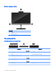
Hardware Reference Guide HP EliteOne 800 G3 23 inch All-in-One Business PC
© Copyright 2017 HP Development Company, L.P. Windows is either a trademark or registered trademark of Microsoft Corporation in the United States and/or other countries. The information contained herein is subject to change without notice. The only warranties for HP products and services are set forth in the express warranty statements accompanying such products and services. Nothing herein should be construed as constituting an additional warranty.
About This Book This guide provides basic information for upgrading this computer model. WARNING! Text set off in this manner indicates that failure to follow directions could result in bodily harm or loss of life. CAUTION: Text set off in this manner indicates that failure to follow directions could result in damage to equipment or loss of information. NOTE: Text set off in this manner provides important supplemental information.
iv About This Book
Table of contents 1 Product features ....................................................................................................................................................................................... 1 Overview .................................................................................................................................................................................... 1 Front components ................................................................................
Webcam ................................................................................................................................................................................... 19 Webcam operation ............................................................................................................................................ 19 Setting up Windows Hello ................................................................................................................................
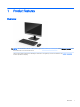
1 Product features Overview NOTE: For the latest manuals on this product, go to http://www.hp.com/support. Select Find your product, and then follow the on-screen instructions. This product employs electronic labeling for indication of regulatory mark or statement. See Labels on page 6 for the operation to display.
Front components Component 1 Webcam 2 Speakers (optional) Top components Infrared (IR) webcam (optional) Component Component Front View 1 Webcam light 4 IR webcam 2 IR light 5 Rear webcam adjustment wheel 3 Full High Definition (FHD) webcam 8 FHD webcam Top view 6 Digital microphones Rear view 7 2 Webcam light Chapter 1 Product features
Full High Definition (FHD) webcam (optional) Component Front view 1 Webcam light 2 FHD webcam Top view 3 Digital microphones Side components Component Component 1 Optical disc drive (optional) 4 Headphone jack 2 Optical disc drive eject button (optional) 5 Fingerprint reader (Touch models only) 3 Audio-out (headphone)/Audio-in (microphone) combo jack Side components 3
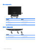
Rear components Component Component 1 DisplayPort 5 RJ-45 (network) jack 2 HDMI port 6 USB 3.1 Type-A ports (2) 3 USB 3.1 Type-A ports (2) 7 Stereo audio-out jack 4 Power connector 8 Security cable slot Bottom components 4 Component Component 1 USB 3.1 Type-A port 4 USB 3.1 Type-C port 2 USB 3.
Keyboard features Your keyboard and mouse may be different.
Labels The labels affixed to the computer provide information you may need when you troubleshoot system problems or travel internationally with the computer. IMPORTANT: computer. 1. All labels described in this section will be located under the stand or affixed to the bottom of the Microsoft® Certificate of Authenticity label (select models only prior to Windows 8)—Contains the Windows Product Key. You may need the Product Key to update or troubleshoot the operating system.
2 Setup Overview Set up the computer in the following order: ● Attach a stand. See Attaching and removing a stand on page 7. Or Attach the computer to a mounting fixture. See Attaching the computer to a mounting fixture on page 10. ● Connect the cables for peripherals and power. See Connecting and disconnecting cables on page 11. ● Connect an additional display, if desired. See Connecting a display on page 11. ● Install and secure the rear port cover. See Installing the rear port cover on page 13.
3. Lower the stand onto the computer and press down until it clicks into place (2). Removing a recline stand To remove the stand: 8 1. Remove all removable media, such as optical discs or USB flash drives, from the computer. 2. Turn off the computer properly through the operating system, then turn off any external devices. 3. Disconnect the AC power cord from the AC outlet and disconnect any external devices. 4. Place the computer face down on a soft flat surface.
Attaching and removing an adjustable height stand Attaching an adjustable height stand To install the stand: 1. Place the computer face down on a soft flat surface. HP recommends that you set down a blanket, towel, or other soft cloth to protect the bezel and screen surface from scratches or other damage. 2. Engage the hooks in the top of the stand in the two large holes in the upper part of the back of the computer (1). 3.
Attaching the computer to a mounting fixture The computer can be attached to a wall, swing arm, or other mounting fixture. NOTE: This apparatus is intended to be supported by UL or CSA Listed wall mount bracket. 1. Press the supplied VESA trim plate onto the VESA opening until it snaps into place. 2.
Connecting and disconnecting cables Connecting cables 1. Place the computer face down on a soft flat surface. HP recommends that you set down a blanket, towel, or other soft cloth to protect the bezel and screen surface from scratches or other damage. 2. If the rear port cover is installed, remove the cover. See Removing the rear port cover on page 12. 3. Route the power and all peripheral cables through the opening in the base of the stand. 4. Connect the peripheral cables to the appropriate ports.
DisplayPort adapters, HDMI adapters, and video cables are purchased separately. HP offers the following adapters: ● DisplayPort to VGA adapter ● DisplayPort to DVI adapter ● HDMI to VGA adapter ● HDMI to DVI adapter To connect a display: 1. Turn off power to the computer and the display that you are connecting to the computer. 2. Remove the rear port cover on the computer. 3.
4. Pull the port cover (3) toward the bottom and off the computer. Installing the rear port cover 1. Be sure that all cables are connected. 2. Hold the port cover parallel to the computer and align the two tabs on the port cover with the slots in the top of the rear port compartment. 3. Slide the port cover (1) in until the tabs click into place. 4. Slide the rear port cover retainer tabs away from each other (2) to lock the port cover in place. 5.
Positioning the computer This computer may ship with a recline stand or an adjustable height stand. ● Adjusting a recline stand ● Adjusting an adjustable height stand Adjusting a recline stand CAUTION: Use caution when reclining a computer if a cable lock is installed. The cable or the lock may interfere with the rotation or the angle of recline. This stand allows you to position the computer from a reclining position to an upright position.
2. Grasp both top and bottom of the computer and press down until the computer is in the desired position. Adjusting an adjustable height stand CAUTION: Use caution when rotating or reclining a computer if a cable lock is installed. The cable or the lock may interfere with the rotation or the angle of recline. This stand allows you to: ● Tilt the computer from –5° to 20° from the desktop ● Adjust the computer height within a range of 110 mm (4.
IMPORTANT: In portrait mode, the recline is limited if a cable lock is installed. 1. Move the stand next to the edge of the desk. 2. Grasp both sides of the computer and lower the computer to your preferred position. 3. Grasp the top and bottom of the computer and tilt the computer to the desired position. CAUTION: When changing the computer orientation between landscape and portrait, be sure that the HP logo on the front of the computer is either on the bottom or the left side.
2. Grasp the upper left and lower right corners of the computer and lift the lower right corner until the computer is in the landscape position. To swivel the computer from side to side: ▲ Grasp both sides of the computer and swivel it up to 45° to one side or the other.
Installing a security cable A security cable is a key lock device that has a wire cable attached. You attach one end of the cable to your desk (or other stationary object) and the other end of the cable to the security cable slot on the computer. Secure the security cable lock with the key. CAUTION: Use caution when adjusting the tilt, swivel, or height of the computer if a security cable is installed. The cable or the lock may interfere with the adjustment.
Disconnecting power 1. Remove all removable media, such as optical discs or USB flash drives, from the computer. 2. Turn off the computer properly through the operating system, then turn off any external devices. 3. Disconnect the power cord from the AC outlet and disconnect any external devices.
Synchronizing the optional wireless keyboard and mouse The wireless keyboard and mouse are optional components. The mouse and keyboard are synchronized at the factory. If they do not work, remove and replace the batteries. If the mouse and keyboard are still not synchronized, then follow this procedure to manually re-synchronize the pair. 1. 2.
3. 4. NOTE: If the mouse and keyboard still do not work, then remove and replace the batteries. If the mouse and keyboard are still not synchronized, then synchronize the keyboard and mouse again.
3 Hardware repair and upgrade Warnings and cautions Before performing upgrades be sure to carefully read all of the applicable instructions, cautions, and warnings in this guide. WARNING! To reduce the risk of personal injury from electrical shock, hot surfaces, or fire: Disconnect the power cord from the AC outlet before removing the enclosure. Energized parts are inside. Allow the internal system components to cool before you touch them.
Removing batteries from the optional wireless keyboard or mouse NOTE: The wireless keyboard and mouse are optional components. To remove batteries from the wireless keyboard, remove the battery door on the underside of the keyboard (1) and lift the batteries out of the battery compartment (2). To remove batteries from the wireless mouse, remove the battery door on the underside of the mouse (1) and lift the batteries out of the battery compartment (2).
Removing and replacing the computer access panel Removing the computer access panel The access panel must be removed to access internal components. 1. Remove all removable media, such as optical discs or USB flash drives, from the computer. 2. Turn off the computer properly through the operating system, and then turn off any external devices. 3. Disconnect the power cord from the AC outlet and disconnect any external devices.
Replacing the computer access panel 1. Align the edges of the access panel with the computer. Press in the tabs around all sides of the panel until it is in place. 2. Reinstall the stand. See Attaching and removing a stand on page 7. 3. Reconnect all cables to the computer. See Connecting cables on page 11. 4. Reinstall the rear port cover. See Installing the rear port cover on page 13. 5. Relock any security devices that were disengaged when the access panel was removed. 6.
Locating internal components Component 26 Component 1 Memory modules 3 Optical disc drive (optional) 2 RTC battery 4 Hard drive Chapter 3 Hardware repair and upgrade
Removing and installing memory The memory slots on the system board can be populated with up to two industry-standard small outline dual inline memory modules (SODIMMs). These memory slots are populated with at least one preinstalled memory module. Memory module specifications For proper system operation, the memory modules must meet the following qualifications: Component Specification Memory modules 1.
remainder is assigned to single channel. If one channel will have more memory than the other, the larger amount should be assigned to channel A. ● In any mode, the maximum operational speed is determined by the slowest memory module in the system. Installing memory modules There are two memory slots on the system board. To remove or install memory modules: 1. Remove the access panel. For instructions, see Removing the computer access panel on page 24. 2.
Replacing the RTC Battery The RTC battery that comes with the computer provides power to the real-time clock. When replacing the battery, use a battery equivalent to the battery originally installed in the computer. The computer comes with a 3-volt lithium coin cell battery. WARNING! The computer contains an internal lithium manganese dioxide battery. There is a risk of fire and burns if the battery is not handled properly. To reduce the risk of personal injury: Do not attempt to recharge the battery.
5. Turn on the computer. 6. Reset the date and time, your passwords, and any special system setups using Computer Setup. Replacing drives Replacing a hard drive The 2.5 inch primary hard drive is installed on the right side of the computer on top of the optical disc drive (ODD). To locate the hard drive on the system board, see Locating internal components on page 26. Removing a hard drive 1. Remove the access panel. For instructions, see Removing the computer access panel on page 24. 30 2.
4. Remove the four mounting screws from the 2.5 inch hard drive. Be sure to keep the screws together with the blue rubber grommets to use to install a replacement drive. For instructions on installing a hard drive, see Installing a 2.5 inch hard disk drive on page 31. Installing a 2.5 inch hard disk drive 1. Fasten four mounting screws with grommets onto the new 2.5 inch hard drive. 2. Position the hard drive above the drive cage with the connectors facing the center of the computer.
3. Place the hard drive into the drive cage and slide it firmly toward the center of the computer until the hard drive snaps into place. Be sure that the hard drive latch has moved back into place to cover the grommet on the side of the hard drive. 4. Install the access panel. For instructions, see Replacing the computer access panel on page 25. Replacing the optical disc drive The optical disc drive is located under the hard drive on the right side of the computer.
3. Push and hold the green tab (1) while pushing in the green latch (2) at the back of the optical disc drive enclosure and slide the drive (3) out of the chassis. 4. Pull the green latch off the optical disc drive. Keep this latch to install on the new optical disc drive. 5. Align the three pins on the latch with the holes in the new optical disc drive and press the latch firmly onto the new drive. NOTE: You must reuse the latch removed from the old optical disc drive.
6. Align the new optical disc drive with the opening in the side of the computer. Push the drive in firmly until it snaps into place. NOTE: 7. The optical disc drive can be installed in only one way. Replace the hard drive. For instructions, see Installing a 2.5 inch hard disk drive on page 31 8. Replace the access panel. For instructions, see Replacing the computer access panel on page 25.
A Electrostatic discharge A discharge of static electricity from a finger or other conductor may damage system boards or other staticsensitive devices. This type of damage may reduce the life expectancy of the device. Preventing electrostatic damage To prevent electrostatic damage, observe the following precautions: ● Avoid hand contact by transporting and storing products in static-safe containers. ● Keep electrostatic-sensitive parts in their containers until they arrive at static-free workstations.
B Computer operating guidelines, routine care, and shipping preparation Computer operating guidelines and routine care Follow these guidelines to properly set up and care for the computer and monitor: ● Keep the computer away from excessive moisture, direct sunlight, and extremes of heat and cold. ● Operate the computer on a sturdy, level surface. Leave a 10.2 cm (4 in) clearance on all vented sides of the computer and above the monitor to permit the required airflow.
Optical disc drive precautions Be sure to observe the following guidelines while operating or cleaning the optical disc drive. ● Do not move the drive during operation. This may cause it to malfunction during reading. ● Avoid exposing the drive to sudden changes in temperature, as condensation may form inside the unit. If the temperature suddenly changes while the drive is on, wait at least one hour before you turn off the power. If you operate the unit immediately, it may malfunction while reading.
C Accessibility HP designs, produces, and markets products and services that can be used by everyone, including people with disabilities, either on a stand-alone basis or with appropriate assistive devices. Supported assistive technologies HP products support a wide variety of operating system assistive technologies and can be configured to work with additional assistive technologies. Use the Search feature on your device to locate more information about assistive features.
Index A access panel removing 24 replacing 25 accessibility 38 additional information 22 adjustable height stand 9 adjustment 15 attaching 9 removing 9 optical disc, replacing types 30 E electronic label 1 electrostatic discharge, preventing damage 35 F features keyboard 5 overview 1 FHD webcam components 3 front components 2 B battery replacement 29 bottom components 4 C cables 11 connecting 11 disconnecting 12 components bottom 4 FHD webcam 3 front 2 internal 26 IR webcam 2 rear 4 side 3 top 2 computer
R rear components 4 rear port cover 12 installing 13 removing 12 recline stand 7 adjustment 14 attaching 7 removing 8 removing 2.