HP Latex 115 Printer User Guide
Edition 3 Legal notices Trademarks © Copyright 2017–2020 HP Development Company, L.P. The information contained herein is subject to change without notice. Microsoft® and Windows® are U.S. registered trademarks of Microsoft Corporation. The only warranties for HP products and services are set forth in the express warranty statements accompanying such products and services. Nothing herein should be construed as constituting an additional warranty.
Table of contents 1 Introduction ............................................................................................................................................................................................... 1 Welcome to your printer .......................................................................................................................................................... 2 Supplementary parts ...................................................................................
The substrate has jammed ................................................................................................................................................... 64 The substrate is deformed or wrinkled .............................................................................................................................. 67 The substrate has shrunk or expanded ..............................................................................................................................
Clean the electrical connections on a printhead ............................................................................................................. 121 Replace the maintenance cartridge .................................................................................................................................. 125 Cannot insert the maintenance cartridge ........................................................................................................................
vi ENWW
1 ENWW Introduction ● Welcome to your printer ● Supplementary parts ● Documentation ● Safety precautions ● The printer’s main components ● The front panel ● The Embedded Web Server ● Connectivity and software instructions ● Advanced network configuration ● Turn the printer on and off ● Restart the printer 1
Welcome to your printer Your printer is a color inkjet printer designed for printing high-quality images on flexible substrates.
The Quick Response (QR) code images found in some parts of this user guide provide links to additional video explanations of particular topics. For an example of such an image, see The printer’s main components on page 7. Safety precautions Before using your printer, read the following safety precautions to make sure you use the equipment safely.
Heat hazard The curing subsystems of the printer operate at high temperatures and can cause burns if touched. To avoid personal injury, take the following precautions. ● Do not touch the internal enclosures of the printer's curing zones. ● Let the printer cool down when accessing the internal curing zone and output platen in case of a substrate jam. ● Let the printer cool down before performing some maintenance operations. Fire hazard The curing subsystems of the printer operate at high temperatures.
● Take care that sleeves or gloves do not get caught in the printer's moving parts. ● Avoid standing close to the fans, which could cause injury and could also affect print quality (by obstructing the air flow). ● Do not touch gears or moving rolls during printing. ● Do not operate the printer with covers bypassed. Light radiation hazard Light radiation is emitted from the illumination of the print zone.
Warnings and cautions The following symbols are used in this manual to ensure the proper use of the printer and to prevent the printer from being damaged. Follow the instructions marked with these symbols. WARNING! death. Failure to follow the guidelines marked with this symbol could result in serious personal injury or CAUTION: Failure to follow the guidelines marked with this symbol could result in minor personal injury or damage to the printer. Warning labels Label Explanation Printer label.
Label Explanation Moving part. Keep away from the moving printhead carriage. When printing, the printhead carriage travels back and forth across the substrate. This label is located on the rear of the scan axis window, behind the plastic. You are recommended to wear gloves when handling the maintenance cartridge or the platen. This label is located on the maintenance cartridge. Electric shock hazard. Heating modules operate at hazardous voltages. Disconnect all power sources before servicing.
Front view 1. Ink cartridge 2. Platen 3. Printhead 4. Printhead carriage 5. Front panel 6. Maintenance cartridge 7. Substrate pinch lever 8. Spindle lock lever 9. Spindle 10. Spindle stop with 2-in to 3-in adaptor 11. Loading table 12.
Rear view 1. Power switch and power socket 2. Sockets for communication cables and optional accessories Take-up reel motor (accessory) ENWW 1. Winding-direction switch 2. Manual winding buttons 3.
The front panel Introduction to the front panel The front panel is a touch-sensitive screen with a graphical user interface; it is located on the front right of the printer. It gives you complete control of your printer: from the front panel, you can view information about the printer, change printer settings, perform calibrations and tests, and so on. The front panel also displays alerts (warning and error messages) when necessary.
Home screen dynamic icons The following items are displayed only on the home screen. ● At the top left of the screen is a message showing the printer status or the most important current alert. Press this message to see a list of all current alerts, with an icon indicating the severity of each alert. You can press an alert to get help in solving the problem. ● At the top right, press ● Press to view substrate status and perform substrate-handling operations.
Change the language of the front panel Two methods are available to change the language that is used for the front-panel menus and messages: ● If you can understand the current front panel language, go to the front panel and press , then Setup > Front panel options > Language. ● If you cannot understand the current front panel language, start with the printer turned off. Turn it on. As soon as the icon appears, press it for a few seconds.
Change the loudspeaker volume To change the volume of the printer's loudspeaker, go to the front panel and press , then Setup > Front panel options > Speaker volume, and select Off, Low, or High. Turn audio alerts on or off To turn the printer's audio alerts on or off, go to the front panel and press , then Setup > Front panel options > Enable audio alert or Disable audio alert. By default, audio alerts are enabled.
● Status ● Estimated ink level ● Warranty status ● Manufacturer ● Capacity ● Product name ● Product number ● Serial number ● Expiration date ● Supported ink cartridges These are the possible ink cartridge status messages that you can see on the front panel: ● OK: The cartridge is working normally, with no known problems. ● Missing: There is no cartridge present, or it is not correctly connected to the printer. ● Low: The ink level is low. ● Very low: The ink level is very low.
Check the status of a printhead The printer automatically checks and services the printheads after each print. Follow these steps to get more information on your printheads: 1. On the front panel's home screen, press 2. Select the printhead for which you want to see information. 3. The front panel shows the following information. ● Status ● Warranty status ● Product name ● Product number ● Serial number ● Ink fired ● Install date .
● Replacement incomplete: The printhead replacement process has not completed successfully; restart the replacement process and let it finish completely. ● Remove: The printhead is not a suitable type for use with your printer. ● Non-HP ink: Ink from a used, refilled, or counterfeit ink cartridge has passed through the printhead. See the limited warranty document provided with your printer for details of the warranty implications.
Clicking an alert opens the application that could help to resolve it. Firmware update advice is dismissed when entering the Printer application. Once dismissed, there won’t be any reminder later on about the same advice (in the case of firmware updates, a new notification appears when there a new firmware release becomes available). ● Embedded Web Server: The Embedded Web Server shows only one alert at a time, which is judged to be the most important.
The front panel offers additional settings for the top and bottom margins: see Table 11-4 Margins on page 150. These settings apply only to single prints when the automatic cutter is not in use. To set the top margin at the front panel, press , then Substrate > Substrate handling options > Extra top margin. To set the bottom margin at the front panel, press , then Substrate > Substrate handling options > Extra bottom margin.
Introduction to the Embedded Web Server The Embedded Web Server is a Web server running inside the printer. You can use it to obtain printer information, manage settings and presets, align printheads, upload new firmware and troubleshoot problems. Service engineers can use it to retrieve internal information that helps to diagnose printer problems. You can access the Embedded Web Server remotely by using an ordinary Web browser running on any computer. See Access the Embedded Web Server on page 20.
● Access HP links for technical support with your printer and accessories ● Access service support pages that show current and historical data on the usage of your printer Networking tab The Networking tab enables you to change the printer’s networking configuration. Printer Data Sharing Agreement tab The Printer Data Sharing Agreement tab enables you to sign the Printer Sharing Data Agreement and configure your participation.
● Change some networking settings. ● Configure the Printer Data Sharing Agreement. ● Run connectivity troubleshooting tests. For more information, see the Embedded Web Server's online help. If you forget the administrator password, you can delete the current password from the front panel: press , then Setup > Connectivity > Advanced > Embedded Web Server > Reset EWS password.
If the test completes successfully, configuration is complete and you can proceed to any other Embedded Web Server page, or close the browser window. If the test fails, follow the instructions to try to identify and fix the problem. The PDSA status and test page of the Printer Data Sharing Agreement tab can be used to check the current status (enabled or not, anonymous data or not), and to run a connectivity test to check that Printer Data Sharing Agreement data can be successfully delivered to HP.
Request email notification of specific error conditions 1. In the Embedded Web Server (see Access the Embedded Web Server on page 20), go to the Email Server page on the Setup tab and ensure that the following fields are correctly filled in: ● SMTP server. This is the IP address of the outgoing mail server (Simple Mail Transfer Protocol [SMTP]) that processes all email messages from the printer. If the mail server requires authentication, email notifications will not work. ● Printer email address.
Request accounting data by email 1. Obtain the IP address of the outgoing mail server (SMTP) from your IT department; this is required in order to send email messages. 2. Ensure that the outgoing email server is configured to enable relaying of email messages that the printer will send. 3. Open your Web browser and connect to the printer’s Embedded Web Server. 4. Select the Setup tab. 5. From the Configuration menu in the left-hand column, select Date & Time. 6.
Connection type Speed Maximum cable length Other factors Gigabit Ethernet Fast; varies according to network traffic Long (100 m=328 ft) Requires extra equipment (switches) NOTE: The speed of any network connection depends on all the components that are used in the network, which can include network interface cards, hubs, routers, switches, and cables. If any one of these components cannot operate at high speed, you will have a low-speed connection.
The stateless and DHCPv6 IPv6 addresses can be used to access the printer, and in most IPv6 networks this will be appropriate. The link-local IPv6 address works only in the local subnet. Although it is possible to access the printer using this address, it is not recommended. It is possible to assign a manual IPv6 address to the printer, using the front panel or the Embedded Web Server. It is also possible to disable IPv6 completely in the printer.
Verify correct operation 1. Print an IO Configuration page to check for status messages. 2. In the upper section of the IO Configuration page, look for the status message I/O Card Ready. 3. If I/O Card Ready appears, the print server is operating properly. Proceed to the next section. If a message other than I/O Card Ready appears, try the following: a. Turn the printer off and then on again to re-initialize the print server. b.
Link troubleshooting If the printer does not successfully connect to the network: ● Both LEDs will be off. ● LAN Error - Loss of Carrier will be indicated on the IO Configuration page. If a link failure is indicated, try the following: ● Check cable connections. ● Print an IO Configuration page and check link settings.
Menu item Sub-menu item Sub-menu item Values and Description IPV4 Settings Config Method Specifies the method that TCP/IPv4 parameters will be configured on the HP Jetdirect print server. Bootp: Use BootP (Bootstrap Protocol) for automatic configuration from a BootP server. DHCP (default): Use DHCP (Dynamic Host Configuration Protocol) for automatic configuration from a DHCPv4 server. If selected and a DHCP lease exists, DHCP Release and DHCP Renew menus are available to set DHCP lease options.
Menu item Sub-menu item Sub-menu item Values and Description Secondary DNS Specify the IP address (n.n.n.n) of a Secondary Domain Name System (DNS) Server. NOTE: This item will appear only if Manual configuration is a higher priority than DHCP in the Config. Precedence table, configured through the embedded Web server. IPV6 Settings Enable Use this item to enable or disable IPv6 operation on the print server. Off: IPv6 is disabled. On (default): IPv6 is enabled.
Menu item Sub-menu item Information Print Sec Page Sub-menu item Values and Description Yes: Prints a page that contains the current security settings on the HP Jetdirect print server. No (default): A security settings page is not printed. Security Secure Web For configuration management, specify whether the embedded Web server will accept communications using HTTPS (Secure HTTP) only, or both HTTP and HTTPS. HTTPS Required: For secure, encrypted communications, only HTTPS access is accepted.
● – Web Proxy (Automatic/Manual cURL) – LLMNR – Telnet (IPv4 only) – SNMP (v1, v2c, v3) agents – Bonjour (for Mac OS X) – FTP (File Transfer Protocol) – Embedded Web Server, HTTP (TCP port 80) – Embedded Web Server, HTTPS (TCP port 443) Printing – ● Raw IP printing (HP-proprietary TCP ports 9100, 9101, 9102) Security – SNMP v3 – SSL/TLS – Firewall Turn the printer on and off To turn on the printer, ensure that the power switch at the rear of the printer is turned on, then press the
To turn it back on later, use the power switch at the rear. If the printer does not start automatically, press the power button. When the printer is turned on, it takes 2–3 minutes to initialize itself. Restart the printer In some circumstances you may be advised to restart the printer. ENWW 1. Turn off the printer by pressing the power button and then turning off the power switch at the rear of the printer. 2. Wait for at least 10 seconds. 3. Turn on the power switch at the rear of the printer. 4.
2 Useful links Product documentation: http://www.hp.com/go/latex115/manuals/ Videos about how to use the printer: http:/www.hp.com/supportvideos/ or http://www.youtube.com/ HPSupportAdvanced Substrate presets: http://www.hp.com/go/mediasolutionslocator (see HP Media Locator on page 74) HP Support: http://www.hp.com/go/latex115/support/ Embedded Web Server: Use the printer’s IP address (see Access the Embedded Web Server on page 20) Registration and communication with HP: http://www.hp.
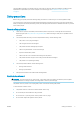
Customer Self Repair HP's Customer Self Repair program offers our customers the fastest service under either warranty or contract. It enables HP to ship replacement parts directly to you (the end user) so that you can replace them. Using this program, you can replace parts at your own convenience. Convenient, easy to use ● An HP Support Specialist will diagnose and assess whether a replacement part is required to address a defective hardware component.
3 36 Handle the substrate and troubleshoot substrate issues ● Overview ● Porous substrates ● Load a roll onto the spindle ● Load a roll into the printer ● Assisted manual load ● The edge holders ● Load a cut sheet into the printer ● Unload a roll from the printer ● The take-up reel (accessory) ● View information about the substrate ● Change substrate width and right edge position ● Substrate length tracking ● Cut substrate ● Bypass job start safety ● Store the substrate ● T
Overview You can print on a wide variety of printing materials, all of which are referred to in this guide as substrates. Substrate tips Choosing the correct substrate for your needs is an essential step in ensuring good print quality. Here are some tips about substrate usage. ● Using the take-up reel with some substrates may give the printer better control of the substrate and is likely to improve print quality. See The take-up reel (accessory) on page 54.
● When printing a series of jobs, do not let the printed substrate obstruct the output path: this can cause severe print-quality defects. ● For more substrate tips, see Load a roll into the printer on page 46 and Assisted manual load on page 49. CAUTION: Removing the substrate from the printer manually without using the front panel could damage the printer. Do this only when necessary to clear a substrate jam.
Substrate category Substrate types Generic substrate names PVC Banner Frontlit banner Generic PVC Banner Backlit banner Generic Backlit PVC Banner Scrim banner Scrimless banner Mesh banner with liner Blockout banner Truck curtain banner or tarpaulin PP and PE Film and Banner Polypropylene (PP) film Generic PP & PE Synthetics Synthetic paper (such as Yupo) Tyvek Coated PE/HDPE (polyethylene) banner PET Film Polyester (PET) backlit film Generic Polyester Film Polyester (PET) frontlit film Gener
Category Substrate Color calib. Textile New HP Light Textile Display Banner No See http://www.globalbmg.com/hp/ Applications Indoor flags, wall murals, interior decoration, fine arts HP Heavy Textile Banner See http://www.globalbmg.com/hp/ HP Satin Canvas Yes 419 microns (16.5 mil) • 370 g/m² • 14.9 m (49 ft) New HP Premium Satin Canvas 463 microns (18.2 mil) • 381 g/m² • 22.9 m (75 ft) New HP Everyday Satin Canvas 444 microns (17.5 mil) • 340 g/m² • 22.
Category Substrate Color calib. New HP Coated Paper, 3 in core Yes Applications 114 microns (4.5 mil) • 90 g/m² • 61 m (200 ft) New HP Universal Heavyweight Coated Paper, 3 in core Yes 165 microns (6.5 mil) • 125 g/m² • 61 m (200 ft) New HP Heavyweight Coated Paper, 3 in core Yes 167 microns (6.6 mil) • 130 g/m² • 61 m (200 ft) New HP Super Heavyweight Plus Matte Paper, 3 in core Yes 259 microns (10.2 mil) • 210 g/m² • 61 m (200 ft) New HP Professional Gloss Photo Paper See http://www.globalbmg.
3. Stick it to the platen as shown. 4. Load the substrate that you want to check. 5. Open your RIP software. 6. Download the test file from inside the printer: http://printerIP/hp/device/webAccess/images/ Ink_trespassing_check.pdf, where printerIP is the IP address of your printer. 7. Print the test file using the number of passes and substrate preset that you intend to use in future with this substrate (or a similar profile in terms of ink limit). 8. Unload the substrate. 9.
2. Lift the spindle lock lever to disengage the spindle. 3. Remove the spindle from the printer. CAUTION: Do not insert your fingers into the spindle supports. The spindle has a stop at each end to keep the roll in position. Remove the blue stop at the left end to mount a new roll (the stop at the other end of a 3 in (76 mm) diameter spindle can also be removed, if you wish). The stop slides along the spindle to hold rolls of different widths. NOTE: 4.
44 5. Remove the stop from the left end of the spindle. 6. Place the roll onto the loading table. 7. Slide the spindle into the roll.
8. The 51 mm (2 in) diameter spindle has only one position for the right stop. There are blue lines on the loading table corresponding to two positions, but when using this spindle you can use only the outer position. 9. Put the blue stop on to the upper end of the spindle, and push it towards the end of the roll. 10. Lock the blue stop when it is in contact with the substrate. 11. Insert the spindle carefully into the printer.
CAUTION: Ensure that the sliders in the loading table are under the left hub, otherwise the spindle will not enter correctly into the left spindle support, and could fall on the floor. If you regularly use different substrates, you can change rolls more quickly if you pre-load rolls of different substrates on different spindles. Extra spindles are available for purchase. Load a roll into the printer To start this procedure, you need to have a roll loaded on the spindle.
2. The load configuration screen appears. ● Skew acceptance: The available values are between 1 and 5, default 3. The printer warns you if the skew is over the limit you have set, but you can still choose to continue loading. ● Length tracking: If you check the box and give the length of your roll, the printer reduces the spare paper when printing and tells you the remaining length. See Substrate length tracking on page 62. ● Assisted manual load. See Assisted manual load on page 49.
4. Select the category and name of the substrate you are loading. You can also search by favorites, or you can select None of these, I will choose it later: by accessing the substrate library after completing the loading procedure. See Substrate presets on page 72. NOTE: You should select the same substrate name that you are using in your RIP software. 5. The printer checks the substrate in various ways and may ask you to correct problems with skew or tension. 6.
8. The printer indicates that it is ready for printing. Take care not to cover the top fans. For instructions on how to use the take-up reel, see The take-up reel (accessory) on page 54. Assisted manual load The assisted manual load procedure should be used in the following cases: ● The substrate is unusually thin or unusually thick. ● The substrate has ragged edges. ● The substrate tends to curl at the edges. ● The printing side of the substrate faces outwards.
You can alternatively begin at step 2, in which case the load configuration screen will appear with this checkbox checked after you lift the pinch lever. Press Continue before taking the next step. 2. Lift the substrate pinch lever as far up as it will go. 3. Carefully insert the leading edge of the substrate above the smooth black roller, making sure the substrate remains taut during the process. Avoid rewinding the substrate manually, unless the printer asks you to do so. 4.
5. Once the substrate is correctly fed into the printer, pull down the substrate pinch lever as far as it will go. 6. Select the category and name of the substrate you are loading. The rest of the assisted load procedure is the same as in the normal load procedure. See Load a roll into the printer on page 46. The edge holders The edge holders are designed to prevent the edges of the substrate from rising while printing is in progress. They are not normally necessary.
Moving part Fragile Wear gloves For more safety information, please see Safety precautions on page 3 Place edge holders 1. There is a hole on the left for the edge holders. Insert an edge holder vertically into the hole. 2. Slide the edge holder into its correct position. 3. Repeat with the other edge holder. Align the substrate When the substrate has been loaded, align it with the white line on the edge holder.
Load a cut sheet into the printer The printer is designed to be used with rolls of substrate. It is possible to load cut sheets into the printer, but print quality cannot be guaranteed, and you may have some difficulty in avoiding skew. ● The sheet should be at least 1067 mm (42 in) long. ● Load the sheet by following the normal roll loading procedure (automatic or manual, depending on the substrate).
Risk of trapped fingers For more safety information, please see Safety precautions on page 3 The take-up reel (accessory) The tension bar When in use, the take-up reel requires a dangling loop of substrate weighed down by a tension bar. The tension bar can be moved with the take-up reel buttons or by using the Move paper or Rewind paper options in the front panel. Load a roll onto the take-up reel NOTE: Take-up reels with 51 mm (2 in) or 76 mm (3 in) diameter can be used.
1. On the printer's front panel, press , then Take-up reel. Instructions are displayed on the screen; slide your finger laterally across the front panel to follow the instructions to the end. 2. If you decide to load the take-up reel during printing, familiarize yourself with the procedural steps before pressing the Enable button. Loading the take-up reel during printing requires you to complete the procedure while the printer is feeding and printing substrate.
5. Remove the take-up reel. 6. Load the core onto the take-up reel. The core should be at least as wide as the substrate. 7. Load the take-up reel into the printer by pushing firmly on both ends. WARNING! Take care not to get your fingers trapped.
8. Advance the substrate by pressing the Move substrate button on the front panel. Make sure that the substrate passes in front of the loading table. 9. Pull down the center of the substrate's leading edge to straighten the substrate. Do not attempt to pull more substrate out of the printer. NOTE: If you are loading the take-up reel during printing, you do not need to pull the substrate taut.
11. Tape the leading edge of the substrate to the core in the center, then at each side. Make sure that the substrate is straight. NOTE: Depending on whether you want to print the images facing in or out, place the tape accordingly. See below. 12. Press the button on the front panel to advance the substrate, creating a loop.
13. Press the blue arrow on the take-up reel motor to rotate the reel one full turn. This will help to support the weight of the tension bar. 14. Press the button on the front panel to advance the substrate again. 15. Gently lower the loading table, to avoid wrinkles and improve winding.
16. Carefully insert the tension bar. This is essential: the take-up reel will not function correctly without it. 17. Fit the tension bar into the supports at either side. WARNING! Take care not to get your fingers trapped. Risk of trapped fingers For more safety information, please see Safety precautions on page 3 18. Use the winding-direction switch on the take-up reel motor to select the winding direction. Setting 1 winds the substrate so that the printed image faces in.
19. Press the Enable button on the front panel. 20. The following image shows how the printer looks when it is operating. As substrate is fed from the printer, it drops down to the tension bar, over the diverter, then down again to the take-up reel. NOTE: When the take-up reel is in use, the substrate is not automatically cut after each print. Unload the take-up reel WARNING! Take care not to get your fingers trapped.
View information about the substrate On the front panel's home screen, press . The following information appears on the front panel, if any substrate is loaded: ● The substrate type ● The substrate name ● The substrate width in millimeters (estimated by the printer) ● The remaining length of the substrate, if known ● The printing zone ● The take-up reel status ● The color calibration status If no substrate is loaded, the message Out of substrate appears.
NOTE: If the cutter is disabled ( , then Substrate handling options > Cutter > Off), the printer advances the substrate but does not cut it. NOTE: Some banners and textiles cannot be cut. Bypass job start safety The job start safety mode is activated by default so that the leading edge of the substrate does not crash under the curing system. If you print with the substrate hanging from the front of the printer, or using the take-up reel, you may want to deactivate this option to improve throughput.
The substrate is mispositioned If you see the above display on the front panel, proceed as follows. 1. Lift the substrate lever. 2. Manually reposition the substrate on the platen. 3. Lower the substrate lever. 4. Repeat the above steps until the front panel displays the Ready message. The substrate has jammed When a jam occurs, the Possible substrate jam message usually appears in the front panel, with one of several error codes (see Front-panel error codes on page 143).
ENWW 2. Open the printer window. 3. Cut the substrate where it enters the printer, and rewind the input roll. 4. Try to move the printhead carriage out of the way. 5. Lift the substrate pinch lever as far up as it will go. 6. Carefully remove as much as possible of the jammed substrate from the top of the printer. Cut the substrate if necessary.
CAUTION: Try to avoid pulling the substrate out through the input path, because this reverses the normal direction of movement, and could damage printer parts. WARNING! Do not touch the printer's curing enclosure, which could be hot. Risk of burns For more safety information, please see Safety precautions on page 3 7. Lower the substrate pinch lever. 8. Make sure that there are no pieces of substrate left in the printer. In particular, check in and under the curing module, and in the substrate path.
● Increase the vacuum level in steps of 10 mmH2O. Do not exceed the following limits: 20 mmH2O for banners, 45 mmH2O for vinyl, and 60 mmH2O for other substrate families. Consider reducing the vacuum percentage at the front of the print zone for thin substrates. ● Increase the number of passes. ● Make sure that the substrate is stored in the same room in which the printer is located. ● Try using the substrate edge holders.
● Paper: less than 0.1% ● PP & PE synthetics: less than 0.4% You are recommended to tile together areas with similar amounts of ink. If this is not possible, print the areas with different amounts of ink as different jobs and modify the length of the job with less ink in the RIP to match its size with the job with high ink content. Some RIPs may provide a scaling option that allows you to compensate easily for substrate shrinkage or expansion; see your RIP documentation.
Automatic cutter does not work The automatic cutter is turned off in any of the following cases: ● When it has been manually disabled from the RIP or from the front panel. To disable the cutter from the front panel, press , then Substrate handling options > Cutter > Off. ● When printing on textiles, PVC banners, or any other substrate types that it cannot cut, the RIP disables the cutter. ● When the take-up reel is enabled.
70 Take-up reel LED status Issue Print job interrupted? Possible cause Possible solution Solid green Take-up reel is not winding No The winding-direction switch on the take-up reel motor is Off or in the wrong position. Ensure that the switch is On, and select the correct winding direction (1 or 2). Solid green Take-up reel is winding in the wrong direction No The winding-direction switch on the take-up reel motor is in the wrong position. Change the switch to the correct position.
4 ENWW Substrate settings ● Substrate presets ● Online search ● HP Media Locator ● Generic presets ● Clone a substrate preset ● Modify a substrate preset ● Add a new substrate ● Delete a substrate preset ● Faster printing ● Color calibration ● ICC profiles ● Improve color consistency when tiling 71
Substrate presets Each substrate type has its own characteristics. To obtain the best print quality, the printer has to adapt its printing parameters to each different substrate type. For example, some may need more ink and some may require higher temperatures for curing. A specification of the correct printing parameters for a particular substrate type is called a substrate preset.
When the printer is connected to the database (this may take a few seconds), a list of all available substrate presets for your printer model is displayed. You can browse the list by scrolling it, and get details on any preset by pressing its name. Besides browsing, there are two additional ways to look for presets: free-text search and filters.
HP Media Locator The HP Media Locator database of substrate presets can also be accessed from a Web browser by visiting http://www.hp.com/go/mediasolutionslocator. This provides access to the database for different regions, printer models, applications, suppliers, substrate types, and so on. When you have located the substrate preset of your choice, you can download it to your computer. To install the preset into the printer with which you want to use it, use the printer's Embedded Web Server.
Clone a substrate preset You may wish to clone and edit a preset for various reasons: ● To assign a name of your own choice to the preset ● To adjust the preset to the precise characteristics of your substrate ● To adjust the preset to your intended use of the substrate, which may range from highest-quality printing to fast production output. To clone a substrate preset, follow these steps: 1. Select a preset in the Substrate Library. 2.
NOTE: The number of passes in an existing print mode cannot be changed. If you want to change the number of passes, create a new print mode. NOTE: You are not allowed to create two print modes with the same number of passes and the same color saturation. To change the values, you must print a test plot. Check it and choose the number in the pull-down colorsaturation menu that matches your preferences in terms of curing and drying.
5. The following screen is displayed: 6. Press the blue button to produce the ink drying and color saturation test print; then continue adjusting the settings and printing again until you are satisfied with the result. NOTE: 7. You can omit this step if you already know the settings that you want to use. If you cannot reach a satisfactory result, you may want to press Advanced settings and try adjusting those settings, which are intended for people who understand their implications.
8. When you have finished, press Continue to perform color calibration. 9. Enter your substrate name and click Start color calibration. See Color calibration on page 81. 10. After the automatic color calibration process has completed, we recommend using the generic ICC profile; alternatively, you can choose to create a new profile or to copy a profile already assigned to a different print mode for this substrate (if there are any such profiles).
Temperature profile Many of the main and advanced substrate settings are related to temperature control, since this is a critical area for correct printing results with latex inks on a wide variety of substrates. NOTE: There is a delay between making a change and seeing the results. See the front panel for actual temperature checking. NOTE: If you selected English units of measurement, you may notice some discrepancies, as the printer works in Celsius and makes the conversion.
Tips ● 2 to 4 passes provide lower print quality. Also, the color gamut will be slightly reduced, as total ink is limited to allow for curing. ● 1200 dpi print resolution is available in the 18-pass print mode only. If you intend to use it, ensure that you have a specific substrate preset for this print mode, because reusing others may not deliver the expected print quality. ● For fast layout proofing on low-cost substrates, a low-ink 2-pass print mode has been enabled.
Color calibration The purpose of color calibration is to produce consistent colors with the specific printheads, inks, and substrate that you are using, and in your particular environmental conditions. After color calibration, you can expect to get very similar prints from your printer on different occasions. Each substrate must be calibrated independently. NOTE: Color calibration may not work correctly with non-HP ink.
3. Manually rewind the take-up reel, using the buttons on the take-up reel motor, to collect the substrate and raise the tension bar until it almost touches the take-up reel. 4. Launch color calibration from the front panel. 5. When the color calibration has finished, you can reset the take-up reel’s winding direction.
● Whenever a new substrate type is introduced that has not yet been calibrated. ● Whenever you notice excessive color differences between prints. Such color differences are mainly caused by aging and wear of the printheads, installing new printheads, and changes in substrate characteristics between one roll and another. You can check the color calibration status of your substrate by pressing on the front panel. ● Recommended status indicates that this substrate has never been calibrated.
2. Select the version of the substrate family that is optimized for tiling. 3. Select the substrate with the most similar properties as a base to add the new one. 4. Select the print mode to create the ICC profile. NOTE: The number of passes must be 8 or more: profiles with fewer passes will not appear on the list. If none of your profiles has enough passes, a default profile will appear. 5. 84 Set the color reference and create the ICC profile.
IMPORTANT: NOTE: Color calibration is mandatory for this kind of print mode. A tiling suffix is added to the substrate name. You can edit the name, but you cannot remove the suffix. Substrates can be exported from one printer to another. When using an imported profile, you are recommended to perform color calibration with the new printer. IMPORTANT: ENWW Old firmware may not allow you to import tiling substrates.
5 Troubleshoot print-quality issues ● General printing advice ● Improve print quality ● 86 – 1. The printhead status plot – 2. The optimizer check plot – 3. The printhead alignment status plot – 4.
General printing advice Use the following approach when you have any print-quality problem: ● Make sure that the substrate type that you select on the front panel, and in your RIP software, is the same as the substrate type that is loaded in the printer. Make sure that the substrate type has been calibrated (including substrate-advance, printhead, and color calibration).
1. The printhead status plot The printhead status plot consists of patterns that are designed to highlight printhead reliability problems. It helps to determine whether any printhead is experiencing clogging or other problems. To print this plot, go to the front panel and press , then Image-quality maintenance > Clean printheads > Print test plot. Vinyl, preferably gloss at least 36 inches wide, is recommended for maximum visibility.
Compare the three rows. ● The row with the symbol shows a simulated image with an above-normal amount of optimizer. ● The row with the symbol shows a simulated image with a below-normal amount of optimizer, equivalent to more than 200 blocked nozzles. ● The row with the rectangle around it and the printing 10 passes.
If there is a clear difference in quality between the rows, there are at least two possible explanations: ● If the quality of the row with the symbol is higher, the substrate is very sensitive to the amount of optimizer. Go to your substrate library on the front panel or in your RIP, select your print mode, and increase the amount of optimizer in the the advanced settings. See Add a new substrate on page 76.
1. Use the same substrate type that you were using when you detected a problem. Or consider using vinyl gloss substrate for better visibility of the optimizer in particular. 2. Go to the front panel and press , then Image-quality maintenance > Align printheads > Print test plot. Check the continuity of the thin diagnostic lines on the alignment status plot. In one section, colored lines are printed in line with black lines to test the alignment from one color to another.
If the printheads are misaligned or you feel unsure about them—for example, because a substrate crash occurred—then align the printheads. See Align the printheads on page 112. 4. The substrate-advance check plot To fine-tune the quality of your print, you may need to adjust the rate at which the substrate advances. The substrate advance determines the placement of dots on the substrate.
Substrate advance adjustment while printing If you are using no more than six passes, you can fine-tune the substrate advance while printing: press , then Adjustments > Adjust substrate advance. Select a value of change from −10 mm/m to +10 mm/m (or mils/ inch). To correct light banding, decrease the value. To correct dark banding, increase the value. If you are using eight passes or more, a wrong advance adjustment will not produce banding but graininess, which is harder to assess visually.
● Use a higher number of passes: you will probably see less grain with ten or more passes. ● If graininess is more visible in light area fills, with the appearance of coalescence graininess (see 2. The optimizer check plot on page 88), try the following solutions: – Go to your substrate library on the front panel or in your RIP. Select your print mode and increase the amount of optimizer in the the advanced settings. See Add a new substrate on page 76. – Clean the optimizer printhead.
Align the printheads on page 112). You can check whether it is necessary by printing the printhead alignment status plot (see 3. The printhead alignment status plot on page 90). ● If banding occurs mostly in black areas, create a new color profile using pure black and not a mixture of other colors. See your RIP documentation. ● Due to the printhead servicing routines while printing, some fibers or small amounts of ink may be deposited on a nozzle, causing it to fail temporarily.
– Increase the vacuum level in steps of 5 mmH2O. Do not exceed the following limits: 20 mmH2O for banners, 45 mmH2O for vinyl, and 50 mmH2O for other substrate families. – In backlit applications, increase the number of passes to 20, maintaining the vacuum level below 20 mmH2O. – If the banding appears only at the beginning of the print, advance the substrate manually about 100– 150 mm before the first print.
2. Use your RIP to add lateral color bars on the side of the plot that is close to the ink supplies. The color bars are designed to exercise all the printhead nozzles, to prevent the problem from occurring. NOTE: Not all RIPs provide this option. 3. Add lateral color bars to the image, manually, before printing. In this case, you can either use the standard colors, or decide to include a particular color in which you have noticed the problem. The recommended width of each color bar is 3 mm. 4.
Ink smears Ink smears may be seen on the print for the following reasons: ● The substrate is skewed. Do not ignore the warning message that appears during the loading procedure if there is significant skew. ● The substrate is not flat in the print zone. Try the following possible solutions. – Increase the vacuum level in steps of 5 mmH2O. – Reduce the curing temperature. You will probably need to increase the number of passes in order to achieve adequate curing.
● When the symptoms appear after reducing the number of passes Increase the curing temperature, decrease the overall ink quantity, and/or modify the inter-path delay offset (in the RIP or front panel) to allow better drying on consecutive passes. ● When the oily finish appears minutes or hours after printing Store the print face-up and uncovered; the effect normally disappears after a while. NOTE: If you decrease the overall ink quantity, you may notice less color saturation.
textiles and banners, will work better without these counterweights, therefore HP strongly recommends uninstalling the Variable Front Tension Kit when it is not needed. The Variable Front Tension Kit can be used with both 54- and 64-inch printers, but with different adjustments. Installation The Variable Front Tension Kit consists of left and right arms, two weights, two M10×180mm screws, six M10 nuts, and four washers. Each arm and each counterweight weighs 1.4 kg. 1.
ENWW 4. Install the subassembly on the left arm of the tension bar, by moving the arms upwards. 5. Install the subassembly on the right arm of the tension bar, by moving the arms upwards.
6. Correct the position of the tension bar after installing the arms. 7. Install the weight at the end of the nut for most substrates. In some cases, you can move the weight forward to reduce the front tension for a particular substrate. 8. For a 64-inch printer: Keep the weights at the furthest position from the tension bar, to provide maximum counterweight torque. 9. For a 54-inch printer: Move the left-hand weight as close as possible to the tension bar, to provide minimum counterweight torque.
6 The ink system ● Ink cartridges ● Printheads ● Maintenance cartridge ● Safe mode Ink cartridges The printer's seven ink cartridges provide magenta, light magenta, black, yellow, light cyan, cyan, and optimizer ink to the printheads. Each cartridge has a capacity of 400 ml. Ink cartridges require no maintenance or cleaning, but must be shaken before installation. High-quality printing results continue even when the ink levels are getting low.
The printheads are extremely durable and do not need to be replaced every time an ink cartridge is replaced. They provide excellent results even when the ink cartridges contain a low level of ink. To maintain optimum print quality, the printheads are automatically tested at regular intervals, and automatically serviced when necessary. This takes a little time and can occasionally delay printing. When a printhead eventually needs to be replaced, the front panel will display a message.
NOTE: The maintenance cartridge is checked to detect end of roll when the printer is turned on and at the end of each print job. The printer will refuse to start a print job if it detects the end of the cleaning roll. You should then replace the maintenance cartridge with a new one. Safe mode Under certain conditions, including printer operation outside of environmental specifications, and when a used, refilled, or counterfeit ink cartridge has been detected, the printer will operate in ‘safe’ mode.
7 Hardware maintenance For the tasks in this chapter, you may need the User Maintenance Kit that was provided with your printer.
Ink system tips For best results, always follow these guidelines: ● Follow the instructions on the front panel during installation. ● Allow the printer and the maintenance cartridge to clean the printheads automatically. ● Avoid unnecessary removal of the ink cartridges and printheads. ● The ink cartridges should never be removed while the printer is printing. They should be removed only when the printer is ready for you to replace them. The front panel guides you through the replacement procedure.
Remove an ink cartridge 1. On the printer's front panel, press Alternatively, press , then Replace ink cartridges. , then Ink > Replace ink cartridges. 2. Grip the blue tab in front of the cartridge that you want to remove. 3. Pull the blue tab down and then pull it outwards, towards you. 4. The cartridge comes out, in its drawer.
5. Lift the cartridge out of its drawer. NOTE: Avoid touching the end of the cartridge that is inserted into the printer, because the connection might be coated with ink. NOTE: If necessary, store a partially-used ink cartridge in the same position as if it were inserted in the printer. Avoid using a partially-used cartridge that has been stored on its end. 6. The front-panel display identifies the missing ink cartridge. Insert an ink cartridge ENWW 1.
4. Insert the ink cartridge into the cartridge drawer. 5. Slide the drawer and cartridge into the slot until they lock into position. 6. The front-panel display confirms that all cartridges have been correctly inserted. Refilled and non-HP ink cartridges HP recommends that you replace an empty cartridge with a new HP cartridge.
CAUTION: Running completely out of ink can damage the printheads. Damage attributable to printing with empty ink cartridges is not covered under the warranty. Forcing the printer to accept empty cartridges will empty the ink delivery system as well. Once emptied, ink must be used to refill the system and reprime the printhead when a new ink cartridge is installed. 1. Install the cartridge in the printer (see Replace an ink cartridge on page 107). 2.
To clean the printheads (which often enables them to recover from problems), go to the printer's front panel and press , then Image-quality maintenance > Clean printheads, then select which printheads you want to clean. You can clean all of the printheads or only some of them. Select from the following options: ● Print test plot ● Clean all ● Clean LM-LC ● Clean K-C ● Clean M-Y ● Clean OP Cleaning all printheads takes about 5 minutes. Cleaning any two printheads takes about 3 minutes.
The printer prints 16 rows labelled from A to P. Inspect the print and write down the number of the straightest line in each row (for example, A:9). Patterns A and B are used to align the HP Latex Optimizer. These will be visible only on certain substrates, such as self-adhesive vinyl. If the best alignment pattern cannot be determined, the default value of 10 should be used.
Front panel recommends reseating or replacing a printhead 1. Remove the printhead and check that it is free from physical damage and from ink stains on the electrical connections. 2. If necessary, clean the electrical connections between the printhead and the carriage. See Clean the electrical connections on a printhead on page 121. 3. Reinsert the printhead into the carriage and check the front panel message. 4. If the problem persists, insert a new printhead.
4. Locate the carriage on the right side of the printer. CAUTION: ENWW Avoid touching the printer's curing enclosure, which may be hot. 5. Pull up and release the latch on top of the carriage. 6. Lift up the cover. This provides access to the printheads.
7. To remove a printhead, lift up the blue handle. 8. Using the blue handle, gently disengage the printhead. 9. Gently pull the blue handle upward until the printhead is released from the carriage. CAUTION: Do not pull abruptly. That action can damage the printhead. CAUTION: If you want to preserve the old printhead for later use, reinstall the cap and plug, but never install a clear optimizer cap or white plug on a non-optimizer printhead.
10. The front-panel display identifies the missing printhead. Insert a printhead 1. If the printhead is new, shake it vigorously before removing the protective caps. Hold the printhead upright (with the protective caps facing down) and shake the printhead vigorously in a smooth up and down motion for about 15 seconds. NOTE: Be careful not to strike the printhead against anything while shaking it, because this could cause damage.
2. Remove the orange protective caps by pulling them down. NOTE: The optimizer protective caps are white or transparent. 3. The printhead is designed to prevent you from accidentally inserting it into the wrong slot. Check that the colored label on the printhead matches the colored label of the carriage slot into which the printhead is to be inserted. 4. Insert the new printhead into its correct slot in the carriage. CAUTION: Insert the printhead slowly and vertically, straight down.
5. Push down as indicated by the arrow. CAUTION: You might feel some resistance when installing the new printhead, so you need to press it down firmly but smoothly. You should hear a beep and see confirmation on the front-panel display that the printhead has been inserted. ENWW 6. Insert all of the other printheads that need to be installed, and close the carriage cover. 7. Make sure that the end of the latch catches the wire loop on the near side of the carriage.
8. Lower the latch to rest on the carriage cover. When all of the printheads have been inserted correctly and the printer has accepted them, the printer beeps. NOTE: If the printer does not beep when you insert the printhead and the Replace message appears on the front-panel display, you might need to reinsert the printhead. 9. Close the printer window. 10. The front-panel display confirms that all of the printheads are correctly inserted. The printer starts checking and preparing the printheads.
Clean the electrical connections on a printhead It is possible that the printer will not recognize a printhead after it has been installed. This can happen when ink builds up on the electrical connections between the printhead and the printhead carriage. Under these circumstances, HP recommends that you clean the electrical connections on the printhead. However, routine cleaning of the connections when no problems are apparent is not recommended.
2. Open the carriage interconnect wiper. 3. Load the sponge by positioning the sponge on the face of the carriage interconnect wiper with the shorter tab in the locating slot. 4. Close the carriage interconnect wiper, trapping the sponge in place. 5. Open the printhead carriage latch and extract the printhead that is causing the problem, as indicated on the front panel. See Replace a printhead on page 114.
6. Insert the carriage interconnect wiper into the printhead slot at the back. Wipe the electrical contacts by inserting the tool between the electrical connections at the back of the slot and the steel spring, with the sponge facing away from you and towards the electrical contacts. Try to avoid picking up any ink deposit that may have accumulated on the bottom surface of the slot.
9. Using the same sponge, clean the lower strip of electrical contacts on the printhead (unless the printhead is new). Avoid touching the upper set of electrical contacts. CAUTION: Do not touch the surface of the printhead that contains the nozzles, because the nozzles are easily damaged. 10. After waiting a few moments to allow both connectors to dry, replace the printhead into the printhead carriage. See Replace a printhead on page 114. 11.
13. Dispose of the soiled sponge in a safe place to prevent the transfer of ink onto hands and clothing. If the front panel continues to show the Reseat or Replace message, replace the printhead or call your service representative. Replace the maintenance cartridge You should replace the maintenance cartridge when prompted to do so by the front panel. TIP: If you want to remove and inspect the maintenance cartridge at any time, you can start the following procedure.
IMPORTANT: When removing a maintenance cartridge, remember that it is full of ink. Therefore: ● Wear gloves. ● Remove it carefully and horizontally to avoid splashing. ● Always handle and store the replaced maintenance cartridge upright. WARNING! Make sure that the printer wheels are locked (the brake lever is pressed down) to prevent the printer from moving. 3. The maintenance cartridge has a handle on the front. To remove the cartridge, just slide it out.
4. When you have slid it out partway, hold it on each side with both hands: it is heavy. IMPORTANT: ENWW Slide it out horizontally to avoid spills, as it is full of ink. 5. Remove the plastic cover from the new maintenance cartridge. 6. Insert the maintenance cartridge into the slot, in the direction indicated by the arrow.
7. Push the maintenance cartridge in until it does not protrude from the slot. You will notice that the printer takes it; do not use excessive force. NOTE: 8. The front panel will not show the new maintenance cartridge until the door is closed. When you have inserted the maintenance cartridge into the printer, close the door.
Moving part Wear gloves For more safety information, please see Safety precautions on page 3 CAUTION: ENWW While cleaning, be careful not to damage the plastic encoder strip located on top of the rod. 4. Wait until the rod is dry, then close the window. The carriage moves to the left side of the printer so that you can reach the part of the rod under the right cover. 5. Open the printer window. 6. Clean the carriage rod area under the right cover as described in step 3. 7.
8. Deposit a very thin zig-zag trickle of oil along the rod. NOTE: 9. While lubricating, be careful not to drop oil on the encoder strip located on top of the rod. Press OK at the front panel. 10. Close the window. 11. The carriage moves from one side of the printer to the other to distribute the oil along the rod. 12. The front panel asks you to confirm that lubrication has been completed. Press OK to confirm.
3. Clean the encoder strip on both sides with a cloth dampened with water, as instructed in the front panel, and press Continue when finished. 4. Close the window. The carriage moves to the left-hand side of the printer. 5. The front panel prompts you to reopen the window and clean the right-hand side of the encoder strip (inside the service station). Press Continue when finished. 6. Close the window. The carriage returns to its ready position in the service station.
5. With a dry brush, remove dry, loosened ink deposits. 6. With the same dry brush, remove dry, loosened ink deposits from the platen surface. 7. Slightly dampen the used cloth with 95% ethanol to wipe the remaining dry ink deposits from the platen. NOTE: Dry ink deposits take longer to remove. NOTE: 95% ethanol is not provided in the User Maintenance Kit. CAUTION: Ethanol is highly flammable. Observe the manufacturer’s safety precautions.
8. Use the damp cloth to remove remaining dry ink deposits. 9. Close the 95% ethanol container and remove it and the cloth from the vicinity of the printer. 10. Wait 3 or 4 minutes to let the ethanol evaporate, before turning on the printer and reloading the substrate. 11. With a 1 mm diameter pin ensure that the vacuum holes are not obstructed, especially the holes that are covered by the most-used substrate sizes.
NOTE: If the printer or ink cartridges are moved from a cold location to a warm and humid location, water from the atmosphere can condensate on the printer parts and cartridges and can result in ink leaks and printer errors. In this case, HP recommends that you wait at least 3 hours before turning on the printer or installing the ink cartridges, to allow the condensate to evaporate. Service maintenance During the life of your printer, components that are used constantly can wear out.
8 Firmware update The printer's various functions are controlled by software that resides in the printer, also known as firmware. From time to time, firmware updates become available from HP. These updates increase the printer's functionality and enhance its features. Firmware update using a USB flash drive When installing the printer for the first time you may be asked to update the firmware. For this purpose, you need a USB flash drive with the following specifications: ● USB 2.
Firmware update using the Embedded Web Server 1. To access the Embedded Web Server from any computer, see Check printer status on page 22. 2. In the Embedded Web Server, select the Setup tab and then Firmware update > Manual firmware update. 3. Follow the on-screen instructions to download the firmware file from http://www.hp.com/go/latex115/ support/ and store it on your hard disk. Then select the downloaded .fmw file and click Update.
9 Accessories To order supplies or accessories, visit http://www.hp.com/go/latex115/accessories on the Web. There you will also see the latest list of supplies and accessories for your printer. The rest of this chapter lists the available supplies and accessories, and their part numbers, at the time of writing. Order ink supplies You can order the following ink supplies for your printer.
Table 9-3 Other supplies Kit Part number HP 831 Latex Maintenance Cartridge CZ681A Order accessories The following accessories can be ordered for your printer. TIP: Spare spindles ease the process of switching between different substrates.
10 Troubleshoot other issues ENWW ● The printer cannot get an IP address ● Cannot access the Embedded Web Server ● The printer is not printing ● The software program slows down or stalls while generating the print job ● The printer seems slow ● Communication failures between computer and printer ● Cannot connect to services such as firmware update, online search, or the Printer Data Sharing Agreement ● Front-panel error codes 139
The printer cannot get an IP address If your network has no DHCP server, the printer cannot automatically retrieve an IP address. In this case, you must set the printer's IP address manually, in the following way: 1. From the front panel, press , then Setup > Network connectivity > Gigabit Ethernet > Modify configuration > TCP/ IP > IPV4 settings > Config method > Manual. 2. From the IPV4 Settings menu, select Manual settings > IP address. 3.
● The network cable is disconnected, or you have problems with your communications setup. See Communication failures between computer and printer on page 141, or contact your IT department or communications system provider. ● One of the following substrate scenarios may exist: – The substrate name that appears on the front panel does not reflect the substrate that is loaded in the printer. – The roll width defined in the RIP for the job does not match the width of the roll in the printer.
To solve a communication problem: ● Make sure that you have selected the correct printer in your RIP. ● Remember that large images usually require more time to receive, process, and print. ● If the printer is connected to your RIP through any other intermediate devices, such as switch boxes, buffer boxes, cable adapters, or cable converters, remove the intermediate device and try connecting the printer directly to your computer. ● Try another interface cable.
Front-panel error codes Under certain circumstances, a numeric error code appears on the front panel. Follow the advice in the Recommendation column to resolve the error. If the recommendation does not seem to solve the problem, call your service representative. See When you need help on page 34. If an error code appears on the front panel that is not included in this list, turn off the printer and then turn it back on. If the problem persists, call your service representative.
Error code Recommendation 14.75:01 Excessive voltage detected. 14.87:10 16.01:00 16.02:00 16.03:00 16.04:00 1. Turn off the printer and unplug both power cords. 2. Check that the power cords are not visibly damaged. 3. Ensure that the input voltage is within specifications (180–264 V AC). 4. Plug in both power cords and make sure they are fully inserted. 5. Turn on the printer. Curing power regulator overtemperature detected. 1. Turn off the printer. 2.
Error code Recommendation 16.11:10 Curing temperature sensor measurement out of range (temperature sensor 1 failed or not connected). 16.12:10 16.13:10 16.14:10 Turn off the printer. 2. Check that the ambient temperature is within printer specifications (15–35°C). 3. Check that the electronic enclosures at the rear of the printer are properly ventilated. 4. Turn on the printer. Curing temperature sensor measurement out of range (temperature sensor 2 failed or not connected). 1.
Error code Recommendation 21.5:03 The part that advances the printhead maintenance cartridge web wipe is blocked. 1. Turn off the printer. 2. Remove and reinsert the maintenance cartridge. 3. Turn on the printer. 4. If the error persists, replace the maintenance cartridge. 25.n:10 (where n = the ink cartridge number) A possible error in the ink cartridge pressure sensor has been detected. The ink level reported may not be accurate. Call your service representative if feasible. 27.
Error code Recommendation 42:03 Scan-axis motor electrical current limit. 63:04 63:05 ENWW 1. Turn off the printer. 2. Open the window and check for any visible obstacles restricting the advance of the substrate. If there is a wrinkled mass of substrate inside the substrate path, lift the substrate pinch lever and clear the obstruction. Carefully remove as much as possible of the jammed substrate from the top of the printer. Cut the substrate if necessary.
Error code Recommendation 86:01, 86.2:01 There is a problem in the carriage assembly. 1. Turn off the printer. 2. Open the window, observing all safety procedures, and check for any visible obstacles restricting the movement of the carriage. If there is a wrinkled mass of substrate inside the substrate path, lift the pinchwheels (using the substrate lever) and clear the obstruction. See also The substrate has jammed on page 64. 3. Turn on the printer.
11 Printer specifications ENWW ● Functional specifications ● Physical specifications ● Memory specifications ● Power specifications ● Ecological specifications ● Environmental specifications ● Acoustic specifications 149
Functional specifications Table 11-1 Ink supplies Printheads Cyan/black, yellow/magenta, light magenta/light cyan, and optimizer Ink cartridges Yellow, black, magenta, light magenta, cyan, light cyan, and optimizer; all cartridges contain 400 ml of ink Maintenance cartridge Non-color-specific Table 11-2 Substrate sizes Width Minimum Maximum 584 mm (23 in) 1372 mm (54 in) Narrow substrate: 254 mm (10 in) Length 1.5 m (59 in) Weight Roll with maximum external diameter of 180 mm (7.
Table 11-4 Margins (continued) Top margin (leading edge) 5 mm (0.2 in) Bottom margin (trailing edge) 5 mm (0.2 in) (none) 100 mm (3.9 in) (small) 150 mm (5.9 in) (normal) 200 mm (7.9 in) (extra) 300 mm (11.8 in) (extra) 400 mm (15.7 in) (extra) 500 mm (19.7 in) (extra) Physical specifications Table 11-5 Printer physical specifications Weight (including stand) 174 kg (384 lb) Width 2307 mm (90.8 in) Depth 840 mm (33.1 in) Height 1380 mm (54.
Ecological specifications For the up-to-date ecological specifications of your printer, please go to http://www.hp.com/ and search for "ecological specifications".
A Summary of common printing problems This is a table of common problems and the parameters that can be changed in order to solve the problem. Some possible side-effects are also shown. For a more detailed treatment of any particular problem, please see the relevant chapter in this guide.
Problem Coalescence graininess in low-tomedium area fills Graininess, color misregistration or lack of sharpness Parameter Change Possible side-effects Vertical correction Activate Grainy aspect Take-up reel (accessory) Use Number of passes Increase Modify the print queue Avoid printing difficult jobs (using a lot of ink) at the beginning of the queue Roll-back tension Increase Grain and/or horizontal banding may appear if too high Warm up printer Activate in RIP Delays the start of prin
ENWW Problem Parameter Change Possible side-effects Subtle color variations in solid areas Color bars Add, manually or in RIP Some waste of substrate and ink Color-variation and text-line correction Apply White areas may appear slightly different.
Glossary Airflow Air is blown through the printing zone to speed up the drying process. Back tension The backwards tension applied to the substrate by the input spindle, which must be constant across the width of the substrate. Too much or too little tension may cause substrate deformation and print quality defects. Bidirectional Bidirectional printing means that the printheads print while moving in both directions. This increases the speed of printing.
Gamut The range of colors and density values reproducible on an output device, such as a printer or monitor. HDPE High Density Polyethylene. I/O Input/Output: this term describes the passing of data between one device and another. ICC The International Color Consortium, a group of companies that have agreed on a common standard for color profiles. Ink density The relative amount of ink that is deposited on the substrate per unit of area.
Substrate-advance compensation A slight adjustment to the amount of substrate advance between print passes, to compensate for the characteristics of different substrate types. The printer normally performs this adjustment automatically, but may need to be recalibrated for substrates not supported by HP, or for an unusual ambient temperature or humidity. Incorrect substrate-advance compensation may cause banding with fewer than 8 passes, or graininess with 8 passes or more.
Index A access control 20 accessories order 138 accounting 23 acoustic specifications 152 alerts by email 23 altitude 12 application hangs up 141 audio alerts on/off 13 B bow deformation 68 brightness of front panel 13 bypass job start safety 63 C calibration color 81 cannot load substrate 63 carriage rod clean and lubricate 128 caution 6 color calibration 81 color profiles 83 communication problems 141 components of printer 7 connect the printer connection method 24 general 25 connect to the Internet 26 c
refill 110 replace 107 specification 150 status 13 ink system status 22 ink system tips 107 internal prints 18 Internet connection 26 troubleshooting 142 IP address 29 IP address, set manually 140 IPv6 25 IPV6 settings 30 J job accounting 23 job start safety, bypass 63 L labels, warning 6 language 12 link speed 31 loading substrate problems loudspeaker volume 13 63 M maintenance cartridge about 104 cannot insert 128 replace 125 specification 150 maintenance, service 134 manuals 2 margins changing 17 spe
length tracking 62 load 46 load cut sheet 53 load onto spindle 42 manual load 49 mispositioned 64 overview 37 porous 41 shrinkage 67 sizes (max & min) 150 storage 63 take-up reel 54 tips 37 unload 53 width, change 62 wrinkled 67 substrate presets 72 clone 75 create 76 delete 80 generic 74 HP Media Locator 74 modify 75 online search 72 substrate-advance adjustment 92 substrate-advance check plot 92 support services HP Customer Care 34 T take-up reel doesn't rewind 69 jam 69 motor 9 using 54 TCP/IP settings 2