Troubleshooting Guide HP t520 Flexible Thin Client
© Copyright 2014 Hewlett-Packard Development Company, L.P. The information contained herein is subject to change without notice. Microsoft and Windows are U.S. registered trademarks of the Microsoft group of companies. The only warranties for HP products and services are set forth in the express warranty statements accompanying such products and services. Nothing herein should be construed as constituting an additional warranty.
About This Book WARNING! Text set off in this manner indicates that failure to follow directions could result in bodily harm or loss of life. CAUTION: Text set off in this manner indicates that failure to follow directions could result in damage to equipment or loss of information. NOTE: Text set off in this manner provides important supplemental information.
iv About This Book
Table of contents 1 Product features ........................................................................................................................................... 1 Standard features .................................................................................................................................................. 1 Front panel components .......................................................................................................................................
Power-On Sequence ............................................................................................................................................ 26 Resetting the Setup and power-on Passwords .................................................................................................. 27 Power-On Diagnostic Tests .................................................................................................................................
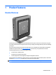
1 Product features Standard features Thank you for purchasing an HP thin client. We hope you have years of use from our thin clients. Our goal is to provide you with award-winning clients that are easy to deploy and manage with the power and reliability you expect. The next sections describe the features of the thin client. For a complete list of the hardware and software installed on a specific model, visit http://www.hp.com and search for your specific thin client model.
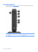
Front panel components For more information, go to http://www.hp.com and search for your specific thin client model to find the model-specific QuickSpecs. 2 (1) Power button (4) USB 3.
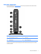
Rear panel components For more information, go to http://www.hp.com and search for your specific thin client model to find the model-specific QuickSpecs. (1) Ethernet RJ-45 port (5) External power adapter input (2) Dual-mode DisplayPort 1.2 ports (2) (6) Cable lock slot (3) VGA port (7) HP USB Legacy Port Module retention slot (4) USB 2.
● If a VGA device is connected at boot up, then only one DisplayPort port may be used. If the VGA device is subsequently disconnected, then both DisplayPort ports are enabled. ● If a VGA device and one DisplayPort device are connected at boot up, then the other DisplayPort port is disabled. If the VGA device is subsequently disconnected, then that DisplayPort port is enabled. ● If two DisplayPort devices are connected at boot up, then the VGA port is disabled.
2 Hardware changes Warnings and cautions Before performing upgrades be sure to carefully read all of the applicable instructions, cautions, and warnings in this guide. WARNING! To reduce the risk of personal injury or equipment damage from electric shock, hot surfaces, or fire: Disconnect the power cord from the power outlet and allow the internal system components to cool before you touch them. Do not plug telecommunications or telephone connectors into the network interface controller (NIC) receptacles.
Connecting the power cord 1. Plug the female end of the power cord into the power supply brick (1). 2. Connect the other end of the power cord to an electrical outlet (2). 3. Connect the round end of the power supply cord to the power supply connector on the rear of the thin client (3). 4. Press the power cord into the retention hook (4) and bundle any excess power cord.
Attaching the stand CAUTION: Unless the thin client is mounted with the HP Quick Release, it must be operated with the stand attached to ensure proper airflow around the thin client. Adjusting the stand The stand can be adjusted into two configurations: square for the horizontal position and rectangular for the vertical position. Take the stand apart by removing the two short pieces connecting the two sides.
● 7. Attach the stand to the right side of the thin client to use it in the horizontal orientation. a. Lay the thin client down with the right side up and locate the two screw holes in the grid on the right side of the thin client. b. Position the stand (1) over the side of the thin client and line up the captive screws in the stand with the screw holes in the thin client. c. Tighten the captive screws (2) securely.
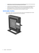
Removing and replacing the access panel Removing the access panel WARNING! To reduce the risk of personal injury or equipment damage from electric shock, hot surfaces, or fire, ALWAYS operate the thin client with the access panel in place. In addition to enhancing safety, the access panel may provide important instructions and identification information, which may be lost if the access panel is not used. DO NOT use any access panel except the one that is provided by HP for use with this thin client.
Replacing the access panel To replace the access panel: 1. Align the three tabs on each side of the access panel with the slots in the chassis. Set the access panel on the chassis, approximately 6 mm (.24 in) inside the edge of the chassis, and then slide the panel toward the front of the chassis (1) into place. 2. Fasten the two screws into the ends of the back I/O panel to secure the access panel (2).
Populating the SODIMM socket There is one SODIMM socket on the system board. The socket is labeled DIMM1. Installing SODIMM CAUTION: You must disconnect the power cord and wait approximately 30 seconds for the power to drain before adding or removing the memory module. Regardless of the power-on state, voltage is always supplied to the memory module as long as the thin client is plugged into an active AC outlet.
12 7. Locate the memory compartment on the system board. 8. To remove the SODIMM, press outward on the two latches (1) on each side of the SODIMM. 9. Rotate the SODIMM up, and then pull the SODIMM out of the socket (2).
10. Slide the new SODIMM (1) into the socket at approximately a 30° angle, and then press the SODIMM into the socket (2) so that the latches lock it in place. NOTE: A memory module can be installed in only one way. Match the notch on the module with the tab on the memory socket. 11. Replace and secure the access panel. See Removing and replacing the access panel on page 9. 12. Replace the thin client stand. 13. Reconnect the power cord and turn on the thin client. 14.
A Removing and replacing the battery WARNING! Before removing the access panel, be sure that the thin client is turned off and the power cord is disconnected from the electrical outlet. To remove and replace the battery: 1. Remove/disengage any security devices that prohibit opening the thin client. 2. Remove all removable media, such as USB flash drives, from the thin client. 3. Turn off the thin client properly through the operating system, and then turn off any external devices. 4.
HP encourages customers to recycle used electronic hardware, HP original print cartridges, and rechargeable batteries. For more information about recycling programs, go to http://www.hp.com and search for “recycle”. Batteries, battery packs, and accumulators should not be disposed of together with the general household waste. In order to forward them to recycling or proper disposal, please use the public collection system or return them to HP, an authorized HP partner, or their agents.
B Computer Setup (F10) Utility, BIOS Settings Computer Setup (F10) Utilities Use Computer Setup (F10) Utility to do the following: ● Change factory default settings. ● Set the system date and time. ● Set, view, change, or verify the system configuration, including settings for processor, graphics, memory, audio, storage, communications, and input devices. ● Modify the boot order of bootable devices such as solid-state drives or USB flash media devices.
5. Use the arrow (left and right) keys to select the appropriate heading. Use the arrow (up and down) keys to select the option you want, then press Enter. To return to the Computer Setup Utilities menu, press Esc. 6. To apply and save changes, select File > Save Changes and Exit. ● If you have made changes that you do not want applied, select Ignore Changes and Exit. ● To reset to factory settings, select Apply Defaults and Exit. This option will restore the original factory system defaults.
Computer Setup—File NOTE: Support for specific Computer Setup options may vary depending on the hardware configuration.
Computer Setup—Storage Option Description Device Configuration Lists all installed BIOS-controlled storage devices. When a device is selected, detailed information and options are displayed. The following options may be presented: Hard Disk: Size, model, firmware version, serial number. Storage Options SATA Emulation CAUTION: SATA emulation changes may prevent access to existing drive data and degrade or corrupt established volumes.
Computer Setup—Security NOTE: Support for specific Computer Setup options may vary depending on the hardware configuration. Table B-1 Computer Setup—Security Option Description Setup Password Allows you to set and enable a setup (administrator) password. NOTE: If the setup password is set, it is required to change Computer Setup options, flash the ROM, and make changes to certain plug and play settings under Windows. Power-On Password Allows you to set and enable a power-on password.
Table B-1 Computer Setup—Security (continued) ● System Security Universal Unique Identifier (UUID) number. The UUID can only be updated if the current chassis serial number is invalid. (These ID numbers are normally set in the factory and are used to uniquely identify the system.) Data Execution Prevention (enable/disable) - Helps prevent operating system security breaches. Default is enabled. Virtualization Technology (enable/disable). Controls the virtualization features of the processor.
Computer Setup—Advanced NOTE: Support for specific Computer Setup options may vary depending on the hardware configuration. Table B-3 Computer Setup—Advanced (for advanced users) Option Heading Power-On Options Allows you to set: ● POST messages (enable/disable). Default is disabled. ● After Power Loss (off/on/previous state). Default is Power off. Setting this option to: ◦ Power off—causes the computer to remain powered off when power is restored.
Changing BIOS Settings from the HP BIOS Configure Utility (HPBCU) Some BIOS settings may be changed locally within the operating system without having to go through the F10 utility1. This table identifies the items that can be controlled with this method.
24 SATA Power Management Enable Disable S5 Maximum Power Savings Disable Enable S5 Wake on LAN Disable Enable POST Messages Disable Enable After Power Loss Off On, Previous State POST Delay (in seconds) None 5, 10, 15, 20, 60 Power on Sunday – Saturday Disable Enable Power on Time (hh:mm) 00:00 00:00:23:59 PCI SERR# Generation Enable Disable PCI VGA Palette Snooping Disable Enable Num Lock State at Power- On On Off Integrated Graphics Auto Disable, Force UMA Frame Buffer
C Diagnostics and Troubleshooting LEDs LED Status Power LED Off When the unit is plugged into the wall socket and the Power LED is off, the unit is powered off. However, the network can trigger a Wake On LAN event in order to perform management functions. Power LED On Displays during boot sequence and while the unit is on.
Wake-on LAN Wake-on LAN (WOL) allows a computer to be turned on or resumed from sleep or hibernation state by a network message. You can enable or disable WOL in Computer Setup using the S5 Maximum Power Savings setting. To enable or disable WOL: 1. Turn on or restart the computer. 2. Press either Esc or F10 while the “Press the ESC key for Startup Menu” message is displayed at the bottom of the screen.
Resetting the Setup and power-on Passwords You can reset the Setup and Power-on passwords as follows: 1. Turn off the computer and disconnect the power cord from the power outlet. 2. Remove the side access panel and the metal side cover. 3. Remove the password jumper from the system board header labeled PSWD/E49. 4. Replace the metal side cover and the side access panel. 5. Connect the computer to AC power, and then turn on the computer. 6.
Interpreting POST Diagnostic Front Panel LEDs and Audible Codes This section covers the front panel LED codes as well as the audible codes that may occur before or during POST that do not necessarily have an error code or text message associated with them. WARNING! When the computer is plugged into an AC power source, voltage is always applied to the system board.
Table C-1 Diagnostic Front Panel LEDs and Audible Codes (continued) Activity Red Power LED flashes six times, once every second, followed by a two second pause. Beeps stop after fifth iteration but LEDs continue until problem is solved. Beeps 6 Possible Cause Pre-video graphics error. Recommended Action 2. Replace memory modules one at a time to isolate the faulty module. 3. Replace third-party memory with HP memory. 4. Replace the system board. For systems with a graphics card: 1.
POST Numeric Codes and Text Messages This section covers those POST errors that have numeric codes associated with them. The section also includes some text messages that may be encountered during POST. NOTE: The computer will beep once after a POST text message is displayed on the screen. Table C-2 Numeric Codes and Text Messages Control panel message Description Recommended action 103-System Board Failure DMA or timers. 1. Clear CMOS. 2. Remove expansion boards. 3. Replace the system board. 1.
Table C-2 Numeric Codes and Text Messages (continued) Control panel message Description Recommended action 510-Flash Screen Image Corrupted Flash Screen image has errors. Reflash the system ROM with the latest BIOS image. 512-Chassis, Rear Chassis, or Front Chassis Fan not Detected Chassis, rear chassis, or front chassis fan is not connected or may have malfunctioned. 1. Reseat chassis, rear chassis, or front chassis fan. 2. Reseat fan cable. 3.
Troubleshooting Basic Troubleshooting If the thin client is experiencing operating problems or will not power on, review the following items. Table C-3 Power-On Troubleshooting Issue Procedures The thin client unit is experiencing operating problems. Ensure that the following connectors are securely plugged into the thin client unit: The thin client unit does not power on. 1. Verify that the power supply is good by installing it on a known working unit and testing it.
Diskless (No-Flash) Unit Troubleshooting This section is only for those units that do not have ATA Flash capability. Because there is no ATA Flash in this model the boot priority sequence is: ● USB device ● PXE 1. When the unit boots, the monitor should display the following information: Table C-4 Diskless Unit Troubleshooting Item Information Action MAC Address NIC portion of the system board is OK If no MAC Address, the system board is at fault. Contact the Call Center for service.
Configuring a PXE Server NOTE: All PXE software is supported by authorized service providers on a warranty or service contract basis. Customers that call the HP Customer Service Center with PXE issues and questions should be referred to their PXE provider for assistance. Additionally, refer to the following: – For Windows 2008 R2: http://support.microsoft.com/kb/891275 – For Windows 2012: http://technet.microsoft.com/en-us/library/cc766320(WS.10).
D Restoring the Flash Image System Requirements To create a recovery device for the purpose of reflashing or restoring the software image on the ROM, you will need the following: ● A personal computer running Microsoft Windows 7. ● One or more HP t520 Flexible Thin Clients ● 8-GB USB flash device for Microsoft Windows Embedded Standard 7 (WES 7) (if using the USB format) or Linux. This restore method will not work with all USB flash devices.
3. Select the USB drive from the list, using the up and down arrows to display the correct drive letter. (If the USB drive does not appear in the list, click Update Drives, then scroll through the list again.) During the next step, the USB drive will be reformatted and all data on it will be erased before the bootable image is copied to it. To prevent loss of data, be sure that you have saved any data from the USB drive to another drive. 4. Click Format.
E Device management The t520 includes a license for HP Device Manager and has a Device Manager agent pre-installed. HP Device Manager is a thin client optimized management tool used to manage the full life cycle of HP thin clients to include Discover, Asset Management, Deployment and Configuration. For more information on HP Device Manager, please visit www.hp.com/go/hpdm. If you wish to manage the t520 with other management tools such as Microsoft SCCM or LANDesk, go to www.hp.
F Adding an Image Restore Tool 1. Ensure that the boot order is set to use the Network as the first boot device. 2. Ensure that IBR.exe (Image Restore) and Flash.dd are stored in the same directory on the server. (e.g., c:\program files\altiris\express\deployment server\images) 3. From the Altiris Deployment Server Console, click File > New > Job . 4. Enter a unique name for the job that you will use to deploy the original thin client image. 5. Click the name of the new job. 6.
G System BIOS Updating or restoring a BIOS HP Device Manager HP Device Manager can be used to update the BIOS of a thin client. Customers can use a pre-built BIOS add-on or can use the standard BIOS upgrade package along with an HP Device Manager File and Registry template. For more information on HP Device Manager File and Registry templates, review the HP Device Manager User Guide found at www.hp.com/go/hpdm.
H Power cord set requirements The power supplies on some computers have external power switches. The voltage select switch feature on the computer permits it to operate from any line voltage between 100-120 or 220-240 volts AC. Power supplies on those computers that do not have external power switches are equipped with internal switches that sense the incoming voltage and automatically switch to the proper voltage.
Country-specific requirements Additional requirements specific to a country are shown in parentheses and explained below. Country Accrediting Agency Country Accrediting Agency Australia (1) EANSW Italy (1) IMQ Austria (1) OVE Japan (3) METI Belgium (1) CEBC Norway (1) NEMKO Canada (2) CSA Sweden (1) SEMKO Denmark (1) DEMKO Switzerland (1) SEV Finland (1) SETI United Kingdom (1) BSI France (1) UTE United States (2) UL Germany (1) VDE 1.
I Statement of Volatility Thin Client products typically have three types of memory devices namely, RAM, ROM, and Flash memory devices. Data stored in the RAM memory device will be lost once the power is removed from the device. RAM devices could be powered by main, aux, or battery power (power states are explained below). Therefore, even when the unit is not connected to an AC outlet, some of the RAM devices could be powered by battery power.
12. Select File > Apply Defaults and Exit. 13. Shut down the computer, remove the AC power cord and place the (blue/green) jumper back on header E49. Replace the computer hood and power cord. Model Description Location/Size Power Loss of data Comments System Boot ROM (BIOS) SPI ROM (64 Mbit) socketed, removable. System memory (RAM) SODIMM socket.
J Specifications For the latest specifications or additional specifications on the thin client, go to http://www.hp.com/go/ quickspecs/ and search for your specific model to find the model-specific QuickSpecs. Dimensions Width 45.1 mm 1.78 in. Depth 200 mm 7.87 in Height (without stand) 200.1 mm 7.88 In Height (with stand) 210.5 mm 8.29 in. Approximate Weight 1,037.1 g 36.59 oz 10°C to 40°C 50°F to 104°F -30°C to 60°C -22°F to 140°F Temperature Range (fanless design)* Operating** (max.
Index A access panel removing 9 replacing 10 adding an image restore tool 38 altitude specifications 44 audible codes 28 B basic troubleshooting 32 battery, replacing 14 beep codes 28 BIOS 39 updating 39 C cable lock slot 3 cautions attaching the stand 7 electric shock 5, 9, 11 installing SODIMM 11 removing the battery 14 securing the power cable 6 static electricity 5 changing BIOS settings in the REPSETUP utility 23 components front panel 2 rear panel 3 country power cord set requirements 41 D diagnostics
U updating a BIOS 39 USB Legacy Module retention slot USB ports 2.0 3 3.