HP Firewalls and UTM Devices Getting Started Guide Part number: 5998-4163 Software version: F1000-A-EI: Feature 3722 F1000-S-EI: Feature 3722 F5000: Feature 3211 F1000-E: Feature 3174 Firewall module: Feature 3174 Enhanced firewall module: ESS 3807 U200-A: ESS 5132 U200-S: ESS 5132 Document version: 6PW100-20121228
Legal and notice information © Copyright 2012 Hewlett-Packard Development Company, L.P. No part of this documentation may be reproduced or transmitted in any form or by any means without prior written consent of Hewlett-Packard Development Company, L.P. The information contained herein is subject to change without notice.
Contents Overview ······································································································································································ 1 F1000-A-EI/F1000-S-EI ···················································································································································· 1 Overview ···············································································································································
Configuring scheme authentication for AUX login ···························································································· 42 Configuring common settings for AUX login (optional)····················································································· 44 Login procedure····················································································································································· 46 Displaying and maintaining CLI login ······················
Configuration guidelines ······································································································································ 91 Configuration procedure ······································································································································ 93 Setting the idle timeout timer in the Web interface ···································································································· 94 Setting the idle timeout timer
Configuring and using command keyword aliases ························································································· 126 Configuring and using hotkeys ·························································································································· 126 Enabling redisplaying entered-but-not-submitted commands ·········································································· 127 Understanding command-line error messages ·····································
Overview This documentation is applicable to the following firewall and UTM products: • HP F1000-S-EI firewall (hereinafter referred to as the F1000-S-EI) • HP F1000-A-EI firewall (hereinafter referred to as the F1000-A-EI) • HP F1000-E firewall (hereinafter referred to as the F1000-E) • HP F5000 firewall (hereinafter referred to as the F5000) • HP firewall modules • HP Enhanced firewall modules • HP U200-A/U200-S Unified Threat Management Products (hereinafter referred to as the UTM) You can
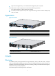
Figure 1 Front view 1: Combo interfaces 2: Console port (CONSOLE) 3: USB port (reserved for future use) Figure 2 Rear view 1 2 3 5 4 1: Power module slot 1 (PWR1) (supports AC/DC power modules) 2: Power module slot 2 (PWR2) (supports AC/DC power modules) 3: Interface module slot 2(Slot 2) 4: Grounding screw 5: Interface module slot 1 (Slot 1) (A NSQ1XS2U0 interface module can be installed only to slot 1) F1000-E Overview The F1000-E is designed for large- and medium-sized networks.
Support for management by its own Web-based management system or by IMC • The F1000-E uses a multi-core processor and provides the following interfaces: • Four combo interfaces, for fiber/copper port switching • Two interface module expansion slots, which support the following interface modules: 4GBE, 8GBE, 1EXP, and 4GBP.
• Protection against external attacks, internal network protection, traffic monitoring, email filtering, Web filtering, application layer filtering • ASPF • Multiple types of VPN services, such as L2TP VPN, GRE VPN, IPsec VPN, and dynamic VPN • RIP/OSPF/BGP routing, routing policy, and policy-based routing • Power module 1+1 redundancy backup (AC+AC or DC+DC) • Multiple types of service interface modules • High availability functions, such as stateful failover and VRRP Appearance Figure 5 Fron
Figure 6 Rear view 1: Rear chassis cover handle (do not use this handle to lift the chassis) 2: (Optional) Air filter 3: Chassis handle 4: Grounding screw and sign 5: Air vents Firewall modules Overview The firewall modules are developed based on the Open Application Architecture (OAA) for carrier-level customers. A firewall module can be installed in the HP 5800/7500E/9500E/12500 Switch or a 6600/8800 router.
Appearance Figure 7 Firewall module for 5800 switches Figure 8 Firewall module for 7500E/9500E/12500 switches Figure 9 Firewall module for 6600/8800 routers Enhanced firewall modules The Enhanced firewall module is a new-generation firewall module developed based on the 40G hardware platform to meet the security-network integration trend and satisfy the ultra-10G Ethernet bandwidth requirements.
• External attack protection, internal network protection, traffic monitoring, URL filtering, application layer filtering. • ASPF • Email alarm, attack log, stream log, and network management monitoring. • Stateful failover (Active/Active and Active/Standby mode), implementing load sharing and service backup. UTM products Overview The HP UTM products are a new generation of professional security devices developed by HP for enterprises.
Appearance U200-A Figure 10 U200-A front view 1: Copper Ethernet ports (GE0 to GE5) 2: Console port (CONSOLE) 3: USB port 4: CF ejector button 5: CF card slot Figure 11 U200-A rear view 1: Grounding screw and sign 2: Power switch (ON/OFF) 3: AC-input power receptacle 4: Interface module slot 1 (SLOT1) 5: Interface module slot 2 (SLOT2) 8
U200-S Figure 12 U200-S front view 1: Copper Ethernet ports (GE0 to GE4) 2: Console port (CONSOLE) 3: USB port 4: CF ejector button 5: CF card slot Figure 13 U200-S rear view 1: AC-input power receptacle 2: Interface module slot (SLOT) 3: Grounding screw and sign Application scenarios F1000-A-EI/F1000-S-EI Firewall application With powerful filtering and management functions, the F1000-A-EI/F1000-S-EI can be deployed at the egress of an internal network to defend against external attacks and contr
Figure 14 Network diagram Virtual firewall application The F1000-A-EI/F1000-S-EI supports the virtual firewall function. You can create multiple virtual firewalls on one firewall. Each virtual firewall can have its own security policy and can be managed independently. Figure 15 Network diagram VPN application The F1000-A-EI/F1000-S-EI supports VPN functions, helping branch offices and remote users securely access the resources in the headquarters and those in their own networks.
Figure 16 Network diagram F1000-E Deployed at the egress of an enterprise network, F1000-E firewalls can protect against external attacks, ensure security access from the external network to the internal network resources (such as servers in the DMZ zone) through NAT and VPN functions, and control access to the internal network by using security zones. You can deploy two firewalls in the network for redundancy backup to avoid a single point failure.
F5000 Large data centers are connected to the 10G core network usually through a 10G Ethernet. The F5000 firewall has a 10G processing capability and abundant port features. It can be deployed at the egress of a network to protect security for the internal network. You can deploy two firewalls to implement stateful failover. • Active-active stateful failover can balance user data. • Active-standby stateful failover improves availability of the firewalls.
Figure 19 Network diagram Enhanced firewall modules Clound computing data center application The Enhanced firewall modules can provide high-performance firewall functions. They also support the virtual firewall function. An Enhanced firewall module can be virtualized into multiple logical firewalls. Each virtual firewall has its own security policy and is managed independently. The virtual firewall function well satisfies the multi-tenant requirements in cloud computing data centers.
Enterprise network applicatoin Deployed in the core switch or the aggregation switch of an enterprise network, the Enhanced firewall module provides security isolation and control of the network zones. Working with the 10500/12500 switch, the Enhanced firewall module can act as the network edge device to protect against external attacks, or as the internal network access control device to isolate different security zones.
UTM Firewall application The UTM Security Products can be deployed at the exits of small- to medium-sized enterprise networks to defend against attacks from the Internet. This type of application has the following advantages: • Integrated security functions that can protect the whole network at application layer. • Powerful attack protection that can protect the internal servers against various attacks.
Figure 24 Network diagram 16
Login overview This chapter describes the available login methods and introduces the related concepts. Login methods at a glance You can access the device through the console port or the Web interface at the first login. After login, you can configure other login methods on the device, such as AUX, Telnet, and SSH.
Login method Default setting and configuration requirements By default, SNMP login is disabled. To use SNMP service, complete the following configuration tasks: • Assign an IP address to an interface of the device and make sure the interface and the NMS can reach each other. By default, only interface GigabitEthernet 0/0 is assigned an IP address (192.168.0.1/24). Accessing the device through SNMP • Configure SNMP basic parameters.
A relative number uniquely identifies a user interface among all user interfaces that are the same type. The number format is user interface type + number: • Console user interface—CON0. • AUX user interface—AUX 0. • VTY user interfaces—Numbered starting from 0 and incrementing by 1.
Logging in to the CLI By default, the first time you access the CLI you must log in through the console port. At the CLI, you can configure Telnet or SSH for remote access. Logging in through the console port for the first time To log in through the console port, make sure the console terminal has a terminal emulation program (for example, HyperTerminal in Windows XP). In addition, the port settings of the terminal emulation program must be the same as the default settings of the console port in Table 3.
Figure 26 Connection description Figure 27 Specifying the serial port used to establish the connection 21
Figure 28 Setting the properties of the serial port 5. Power on the device and press Enter at the prompt. Figure 29 CLI 6. At the default user view prompt , enter commands to configure the device or view the running status of the device. To get help, enter ?. Configuring console login control settings The following authentication modes are available for controlling console logins: • None—Requires no authentication. This mode is insecure. • Password—Requires password authentication.
Scheme—Uses the AAA module to provide local or remote console login authentication. You must provide a username and password for accessing the CLI. For more information about authentication modes and parameters, see Access Control Configuration Guide. Keep your username and password. • By default, console login does not require authentication. Any user can log in through the console port without authentication and have user privilege level 3.
Configuring password authentication for console login Step Command Remarks 1. Enter system view. system-view N/A 2. Enter console user interface view. user-interface console first-number [ last-number ] N/A 3. Enable password authentication. authentication-mode password By default, you can log in to the device through the console port without authentication and have user privilege level 3 after login. 4. Set a password.
Step 3. Enable scheme authentication. Command Remarks authentication-mode scheme Whether local, RADIUS, or HWTACACS authentication is adopted depends on the configured AAA scheme. By default, console login users are not authenticated. Optional. 4. Enable command authorization. command authorization By default, command authorization is disabled. The commands available for a user only depend on the user privilege level. Optional. 5. Enable command accounting. command accounting 6.
The next time you attempt to log in through the console port, you must provide the configured login username and password. Configuring common console user interface settings (optional) Some common settings configured for a console user interface take effect immediately and can interrupt the console login session. To save you the trouble of repeated re-logins, use a login method different from console login to log in to the device before you change console user interface settings.
Step Command Remarks By default, the terminal display type is ANSI. 9. Specify the terminal display type. 10. Configure the user privilege level for login users. terminal type { ansi | vt100 } user privilege level level 11. Set the maximum number of lines to be displayed on a screen. screen-length screen-length 12. Set the size of command history buffer. history-command max-size value 13. Set the idle-timeout timer.
Table 5 shows the Telnet server and client configuration required for a successful Telnet login. Table 5 Telnet server and Telnet client configuration requirements Device role Requirements Enable Telnet server. Telnet server Assign an IP address to an interface of the device, and make sure the Telnet server and client can reach each other. By default, only interface GigabitEthernet 0/0 is assigned an IP address (192.168.0.1/24). Configure the authentication mode and other settings.
Authentication mode Configuration tasks Reference Enable scheme authentication on the VTY user interface. Configure local or remote authentication settings. To configure local authentication: 14. Configure a local user and specify the password. 15. Configure the device to use local authentication. Scheme To configure remote authentication: 16. Configure the RADIUS or HWTACACS scheme on the device. "Configuring scheme authentication for Telnet login" 17.
Figure 31 Telnetting to the device without authentication Configuring password authentication for Telnet login Step Command Remarks 1. Enter system view. system-view N/A 2. Enable Telnet server. telnet server enable By default, the Telnet server function is disabled. 3. Enter one or multiple VTY user interface views. user-interface vty first-number [ last-number ] N/A 4. Enable password authentication.
Figure 32 Password authentication interface for Telnet login Configuring scheme authentication for Telnet login When scheme authentication is used, you can choose to configure the command authorization and command accounting functions. If command authorization is enabled, a command is available only if the user has the commensurate user privilege level and is authorized to use the command by the AAA scheme.
Step 3. 4. Enter one or multiple VTY user interface views. Enable scheme authentication. Command Remarks user-interface vty first-number [ last-number ] N/A authentication-mode scheme Whether local, RADIUS, or HWTACACS authentication is adopted depends on the configured AAA scheme. By default, local authentication is adopted. Optional. 5. Enable command authorization. command authorization By default, command authorization is disabled.
Step Command Remarks 14. Configure common settings for VTY user interfaces. See "Configuring common VTY user interface settings (optional)." Optional. The next time you attempt to Telnet to the CLI, you must provide the configured login username and password, as shown in Figure 33. If you are required to pass a second authentication, you must also provide the correct password to access the CLI.
Step Command Remarks Optional. Enable the user interfaces to support Telnet, SSH, or both of them. protocol inbound { all | ssh | telnet } 5. Define a shortcut key for terminating tasks. escape-key { default | character } 6. Configure the type of terminal display. 7. Set the maximum number of lines to be displayed on a screen. 4. By default, both Telnet and SSH are supported. The configuration takes effect the next time you log in. Optional. By default, pressing Ctrl+C terminates a task.
Figure 34 Telnetting from the device to a Telnet server To use the device to log in to a Telnet server: Step Command Remarks N/A 1. Enter system view. system-view 2. Specify the source IPv4 address or source interface for outgoing Telnet packets. telnet client source { interface interface-type interface-number | ip ip-address } By default, no source IPv4 address or source interface is specified. The device automatically selects a source IPv4 address. 3. Exit to user view. quit N/A Optional.
Table 7 SSH server and client requirements Device role Requirements SSH server Assign an IP address to an interface of the device, and make sure the interface and the client can reach each other. By default, only interface GigabitEthernet 0/0 is assigned an IP address (192.168.0.1/24). Configure the authentication mode and other settings. SSH client If a host operates as an SSH client, run the SSH client program on the host. Obtain the IP address of the interface on the server.
Step Command Remarks 4. Enter one or multiple VTY user interface views. user-interface vty first-number [ last-number ] N/A 5. Enable scheme authentication. authentication-mode scheme By default, the authentication mode for VTY user interfaces is scheme. 6. Enable the user interfaces to support Telnet, SSH, or both of them. Optional. protocol inbound { all | ssh } By default, both Telnet and SSH are supported. Optional. 7. Enable command authorization.
Step Command Remarks 14. Specify SSH service for the user. service-type ssh By default, the system-predefined user admin can use terminal service, Telnet service, SSH service, and Web service, and no service type is specified for any other local user. 15. Exit to system view. quit N/A 16. Create an SSH user, and specify the authentication mode for the SSH user.
Hardware Feature compatible F1000-E Yes F5000 Yes Firewall module No U200-A No U200-S No As shown in Figure 37, to perform local login through the AUX port, use the same cable and login procedures as console login. For a device with separate console and AUX ports, you can use both ports to log in to the device. Figure 37 AUX login diagram To control AUX logins, configure authentication and user privilege for AUX port users.
Authentication mode Configuration tasks Reference Enable scheme authentication on the AUX user interface. Configure local or remote authentication settings. To configure local authentication: 18. Configure a local user and specify the password. 19. Configure the device to use local authentication. Scheme To configure remote authentication: 20. Configure the RADIUS or HWTACACS scheme on the device. "Configuring scheme authentication for AUX login." 21.
Figure 38 Accessing the CLI through the AUX port without authentication Configuring password authentication for AUX login Step Command Remarks 1. Enter system view. system-view N/A 2. Enter one or more AUX user interface views. user-interface aux first-number [ last-number ] N/A 3. Enable password authentication. authentication-mode password By default, password authentication is enabled but no password is configured.
Figure 39 Password authentication interface for AUX login Configuring scheme authentication for AUX login When scheme authentication is used, you can choose to configure the command authorization and command accounting functions. If command authorization is enabled, a command is available only if the user has the commensurate user privilege level and is authorized to use the command by the AAA scheme.
Step 3. Enable scheme authentication. Command Remarks authentication-mode scheme By default, password authentication is enabled on AUX user interfaces. Optional. 4. Enable command authorization. command authorization By default, command authorization is disabled. The commands available for a user only depend on the user privilege level. Optional. 5. Enable command accounting. command accounting 6. Exit to system view. quit By default, command accounting is disabled.
Figure 40 Scheme authentication interface for AUX login Configuring common settings for AUX login (optional) Some common settings configured for an AUX user interface take effect immediately and can interrupt the login session. To save you the trouble of repeated re-logins, use a login method different from AUX login to log in to the device before you change AUX user interface settings.
Step Command Remarks The default is 1. 6. Specify the number of stop bits. stopbits { 1 | 1.5 | 2 } Stop bits indicate the end of a character. The more the bits, the slower the transmission. By default, the number of data bits in each character is 8. The setting depends on the character coding type. For example, you can set it to 7 if standard ASCII characters are to be sent, and set it to 8 if extended ASCII characters are to be sent. 7. Specify the number of data bits in each character.
The port properties of the terminal emulation program must be the same as the default settings of the AUX port, which are shown in the following table: Parameter Default Bits per second 9600 bps • Independent AUX port: On Flow control • Console and AUX integrated port: Off Parity None Stop bits 1 Data bits 8 Login procedure To log in through the AUX port: • Complete the authentication settings on the AUX user interface. By default, password authentication is enabled, but no password is set.
Figure 41 Connecting the AUX port to a terminal 3. If the PC is off, turn on the PC. 4. Launch the terminal emulation program and configure the communication properties on the PC. Figure 42 through Figure 44 show the configuration procedure on Windows XP HyperTerminal. Make sure the port settings are the same as the common AUX port settings on the device. If the default settings are used, see Table 9.
Figure 43 Specifying the serial port used to establish the connection Figure 44 Setting the properties of the serial port 5. Power on the device and press Enter at the prompt.
Figure 45 CLI 6. At the default user view prompt , enter commands to configure the device or check the running status of the device. To get help, enter ?. Displaying and maintaining CLI login Task Command Remarks Display information about the user interfaces that are being used. display users [ | { begin | exclude | include } regular-expression ] Available in any view. Display information about all user interfaces the device supports.
Task Command Remarks Send messages to user interfaces. send { all | num1 | { aux | console | vty } num2 } Available in user view.
Logging in to the Web interface The device provides a built-in Web server for you to configure the device through a Web browser. Web login is by default enabled. Configuration guidelines • The Web-based configuration interface supports the operating systems of Windows XP, Windows 2000, Windows Server 2003 Enterprise Edition, Windows Server 2003 Standard Edition, Windows Vista, Windows 7, Linux, and MAC OS. • The Web-based configuration interface supports the browsers of Microsoft Internet Explorer 6.
Up to five users can concurrently log in to the device through the Web interface. Figure 46 Web login page Adding a Web login account Perform the following configuration at the CLI: 1. Add a Web user. Set the username to userA, password to 123456, and user privilege level to 3. [HP] local-user userA New local user added. [HP-luser-userA] service-type web [HP-luser-userA] password simple 123456 [HP-luser-userA] authorization-attribute level 3 [HP-luser-userA] quit 2.
Table 10 Basic Web login configuration requirements Object Requirements Assign an IP address to an interface. Configure routes to make sure the interface and the PC can reach each other. Device Perform either or both of the following tasks: • Configuring HTTP login • Configuring HTTPS login Install a Web browser. PC Obtain the IP address of the device's interface. Configuring HTTP login Step Command Remarks Optional. 1. Specify a fixed verification code for Web login.
Step Command Remarks 10. Specify the command level of the local user. authorization-attribute level level No command level is configured for the local user. 11. Specify the Telnet service type for the local user. service-type web By default, the system-predefined user admin can use terminal service, Telnet service, SSH service, and Web service, and no service type is specified for any other local user. 12. Exit to system view. quit N/A 13. Enter interface view.
Step Command Remarks Optional. By default, the HTTPS service is not associated with any SSL server policy, and the device uses a self-signed certificate for authentication. 3. Associate the HTTPS service with an SSL server policy. ip https ssl-server-policy policy-name If you disable the HTTPS service, the system automatically de-associates the HTTPS service from the SSL service policy. Before re-enabling the HTTPS service, associate the HTTPS service with an SSL server policy first.
Step 7. Command Associate the HTTPS service with an ACL. Remarks By default, the HTTPS service is not associated with any ACL. ip https acl acl-number Associating the HTTPS service with an ACL enables the device to allow only clients permitted by the ACL to access the device. Optional. By default, a user must enter the correct username and password to log in through HTTPS. When the auto mode is enabled: 8. Specify the authentication mode for users trying to log in to the device through HTTPS.
Displaying and maintaining Web login Task Command Remarks Display information about Web users. display web users [ | { begin | exclude | include } regular-expression ] Available in any view. Display HTTP state information. display ip http [ | { begin | exclude | include } regular-expression ] Available in any view. Display HTTPS state information. display ip https [ | { begin | exclude | include } regular-expression ] Available in any view.
2. Verify the configuration: # On the PC, launch a Web browser and enter the IP address of the interface in the address bar. The Web login page appears, as shown in Figure 48. Figure 48 Web login page # Enter the username, password, verification code, and click Login. The homepage appears. After login, you can configure device settings through the Web interface.
# Create a PKI domain, specify the trusted CA as new-ca, the URL of the server for certificate request as http://10.1.2.2/certsrv/mscep/mscep.dll, authority for certificate request as RA, and the entity for certificate request as en. [Firewall] pki domain 1 [Firewall-pki-domain-1] ca identifier new-ca [Firewall-pki-domain-1] certificate request url http://10.1.2.2/certsrv/mscep/mscep.
On the host, run the IE browser, and then enter http://10.1.2.2/certsrv in the address bar and request a certificate for the host as prompted. 3. Verify the configuration: Enter https://10.1.1.1 in the address bar, and select the certificate issued by new-ca. When the Web login page of the firewall appears, enter the username usera and password 123 to log in to the Web management page.
Figure 50 Internet Explorer setting (I) 3. Click Custom Level. The dialog box Security Settings appears. 4. Enable Run ActiveX controls and plug-ins, script ActiveX controls marked safe for scripting and active scripting.
Figure 51 Internet Explorer setting (II) 5. Click OK in the Security Settings dialog box. Configuring Firefox Web browser settings 1. Open the Firefox Web browser, and select Tools > Options. 2. Click the Content tab, select the Enable JavaScript box, and click OK.
Figure 52 Firefox Web browser setting 63
Accessing the device through SNMP NOTE: Accessing the device through SNMP is not supported in FIPS mode. You can run SNMP on an NMS to access the device MIB and perform GET and SET operations to manage and monitor the device. The device supports SNMPv1, SNMPv2c, and SNMPv3, and can work with various network management software products, including IMC. For more information about SNMP, see System Management and Maintenance Configuration Guide. By default, SNMP access is disabled.
Step Command Remarks Optional. 2. 3. 4. Enable the SNMP agent. By default, the SNMP agent is disabled. snmp-agent You can enable SNMP agent with this command or any command that begins with snmp-agent. Configure an SNMP group and specify its access right. snmp-agent group v3 group-name [ authentication | privacy ] [ read-view read-view ] [ write-view write-view ] [ notify-view notify-view ] [ acl acl-number | acl ipv6 ipv6-acl-number ] * Add a user to the SNMP group.
Step Command Remarks • (Approach 1) Specify the SNMP NMS access right directly by configuring an SNMP community: snmp-agent community { read | write } community-name [ mib-view view-name ] [ acl acl-number | acl ipv6 ipv6-acl-number ] * • (Approach 2) Configure an SNMP group 4. Configure the SNMP access right. and add a user to the SNMP group: a.
2. Configure the NMS: Make sure the NMS has the same SNMP settings, including the username as the firewall. If not, the firewall cannot be discovered or managed by the NMS. 3. Use the network management station to discover, query, and configure the firewall. For more information, see the NMS manual.
Logging in to the firewall module from the network device Feature and hardware compatibility Hardware Feature compatible F1000-A-EI/F1000-S-EI No F1000-E No F5000 No Firewall module Yes U200-A No U200-S No This chapter describes how to log in to the firewall module from the network device. Other login methods for the firewall module are the same as a firewall.
After login, the terminal screen displays the CLI of the firewall module. To return to the CLI on the device, press Ctrl+K. Monitoring and managing the firewall module on the network device Resetting the system of the firewall module CAUTION: The reset operation may cause data loss and service interruption.
An ACSEI server can register multiple ACSEI clients. ACSEI timers An ACSEI server uses two timers, the clock synchronization timer and the monitoring timer: • The clock synchronization timer is used to periodically trigger the ACSEI server to send clock synchronization advertisements to ACSEI clients. You can set this timer through command lines. • The monitoring timer is used to periodically trigger the ACSEI server to send monitoring requests to ACSEI clients.
Configuring ACSEI client on the firewall module Step Command Remarks 1. Enter system view. system-view N/A 2. Enter interface view interface interface-type interface-number N/A Disabled by default. 3. Enable the ACSEI client acsei-client enable The Comware platform can run only one ACSEI client, that is, the ACSEI client can be enabled on only one interface at a time. But the ACSEI client on the Comware platform and that on the firewall module can run simultaneously.
Figure 55 Network diagram Configuration procedure This example uses a switch. The configuration on a router is the same. 1. Log in to the firewall module from the network device: # Configure the AUX user interface of the firewall module. system-view [FW module] user-interface aux 0 [FW module-ui-aux0] authentication-mode none [FW module-ui-aux0] user privilege level 3 [FW module-ui-aux0] # Log in to the firewall module. oap connect slot 3 Connected to OAP! 2.
# acsei server acsei timer clock-sync 10 acsei timer monitor 10 # return [Switch] The output shows that the clock synchronization timer and monitoring timer are 10 minutes and 10 seconds, respectively.
Basic configuration Overview Basic configuration information include: • Device name and login password—Modify the system name and the password of the current user. • Service management—Specify whether to enable the services like FTP, Telnet, HTTP, and HTTPS, and set port numbers for HTTP and HTTPS. • Interface IP address—Configure IP addresses for Layer 3 Ethernet interfaces and VLAN interfaces. • NAT—Configure dynamic NAT, internal server translation, and related parameters.
Figure 56 Basic configuration wizard—1/6 3. Click Next. The page for basic configuration appears.
Figure 57 Basic configuration wizard—2/6 (basic information) 4. Configure the parameters as described in Table 11. Table 11 Configuration items Item Description Sysname Enter the system name. Modify Current User Password Specify whether to modify the login password of the current user. New Password To modify the password of the current user, set the new password and the confirm password, and the two passwords must be identical.
Figure 58 Basic configuration wizard—3/6 (service management) 6. Configure the parameters as described in Table 12. Table 12 Configuration items Item FTP Telnet Description Specify whether to enable FTP on the device. Disabled by default. Specify whether to enable Telnet on the device. Disabled by default. Specify whether to enable HTTP on the device, and set the HTTP port number. Enabled by default.
Item Description Specify whether to enable HTTPS on the device, and set the HTTPS port number. Disabled by default. IMPORTANT: • If the current user logged in to the Web interface through HTTPS, disabling HTTPS HTTPS or modifying the HTTPS port number will result in disconnection with the device. Therefore, perform the operation with caution. • When you modify a port number, make sure the port number is not used by another service. • By default, HTTPS uses the PKI domain default.
Table 13 Configuration items Item Description Set the approach for obtaining the IP address, including: • None—The IP address of the interface is not specified. The interface has no IP address. • Static Address—Specify the IP address for the interface IP Configuration manually. If you select this item, specify both the IP address and the mask. • DHCP—The interface obtains an IP address automatically through the DHCP protocol. • Do not change—The IP address of the interface does not change.
Table 14 Configuration items Item Description Interface Select an interface on which the NAT configuration will be applied. Specify whether to enable dynamic NAT on the interface. Dynamic NAT If dynamic NAT is enabled, the IP address of the interface will be used as the IP address of a matched packet after the translation. By default, dynamic NAT is disabled. Source IP/Wildcard If dynamic NAT is enabled, set the source IP address and wildcard for packets.
Figure 61 Basic configuration wizard—6/6 On this page, you can set whether to save the current configuration to the startup configuration file (which can be .cfg or .xml file) for the next device boot when you submit the configurations. 12. Click Finish to confirm the configurations. To modify your configuration, click Back to go back to the previous page. Performing basic configuration at the CLI Step Command Remarks N/A 1. Enter system view. system-view 2. Change the device name.
Step Command Remarks • To configure a static NAT mapping: a. nat static local-ip [ vpn-instance local-name ] global-ip [ vpn-instance global-name ] b. interface interface-type interface-number c. nat outbound static 4. Configure NAT. • To configure dynamic NAT: d. interface interface-type interface-number Optional. By default, NAT is not configured on an interface. e.
Step Command Remarks import interface interface-type interface-number [ vlan vlan-list ] By default, GigabitEthernet 0/0 belongs to the Management zone and the other interfaces do not belong to any zone. 10. Return to system view. quit N/A 11. Save the running configuration to the configuration file and specify the file as the next-startup configuration file. save [ safely ] This command is available in any view. 12. Display the running configuration. display current-configuration 9.
Managing the device Device management includes monitoring the operating status of devices and configuring their running parameters. The configuration tasks in this document are order independent. You can perform these tasks in any order. Feature and hardware compatibility Hardware Supported storage medium F1000-A-EI/F1000-S-EI flash0 F1000-E cfa0 F5000 cfa0 Firewall module cfa0 U200-A cfa0 U200-S cfa0 For description convenience, all examples in this chapter use the storage medium cfa0.
To configure the device name: Step Command Remarks 1. Enter system view. system-view N/A 2. Configure the device name. sysname sysname The default device name is HP. Configuring the system time in the Web interface A correct system time setting is essential to communication and network management. System time allows you to display and set the device system time, time zone, and daylight saving time on the Web interface.
Figure 64 Calendar page 3. Modify the system time either in the System Time Configuration text box, or through the calendar page. You can perform the following operations on the calendar page: { { 4. Click Today to set the current date on the calendar to the current system date of the local host, and the time stays unchanged. Set the year, month, date and time, and then click OK. Click Apply in the system time configuration page to save your configuration. Configuring the network time 1.
Table 15 Configuration items Item Description Clock status Displays the synchronization status of the system clock. Set the IP address of the local clock source to 127.127.1.u, where u ranges from 0 to 3, representing the NTP process ID. Local Reference Source • If the IP address of the local clock source is specified, the local clock is used as the reference clock, and thus can provide time for other devices.
Figure 66 Setting the time zone 3. Configure the time zone and daylight saving time as described in Table 16. 4. Click Apply. Table 16 Configuration items Item Description Time Zone Set the time zone for the system. Adjust the system clock for daylight saving time changes, which means adding one hour to the current system time. Click Adjust clock for daylight saving time changes to expand the option, as shown in Figure 67.
Figure 68 Network diagram Configuration procedure 1. On Device A, configure the local clock as the reference clock, with the stratum 2: a. Select Device Management > System Time from the navigation tree. b. Click Network Time Protocol. The page for setting up NTP appears. c. Select 127.127.1.1 from the Local Reference Source list. d. Select 2 from the Stratum list. e. Click Apply. Figure 69 Configuring the local clock as the reference clock 2.
Figure 70 Configuring Device A as the NTP server of Device B 3. Verifying the configuration After the configuration, you can see that the current system time displayed on the System Time page is the same for Device A and Device B. Configuration guidelines A device can act as a server to synchronize the clock of other devices only after its clock has been synchronized.
Configuration guidelines You can change the system time by configuring the relative time, time zone, and daylight saving time. The configuration result depends on their configuration order (see Table 17). In the first column of this table, 1 represents the clock datetime command, 2 represents the clock timezone command, and 3 represents the clock summer-time command. To verify the system time setting, use the display clock command. This table assumes that the original system time is 2005/1/1 1:00:00.
Command Effective system time Configuration example date-time outside the daylight saving time range: clock datetime 1:00 2007/1/1 clock summer-time ss one-off 1:00 2006/1/1 1:00 2006/8/8 2 date-time System time 01:00:00 UTC Mon 01/01/2007. 10:00:00 ss Mon 01/01/2007.
Command Effective system time Configuration example System time clock datetime 1:00 2007/1/1 date-time ± zone-offset outside the daylight saving time range: clock timezone zone-time add 1 clock summer-time ss one-off 1:00 2008/1/1 1:00 2008/8/8 2 date-time ± zone-offset 1, 2, 3 or 1, 3, 2 02:00:00 zone-time Mon 01/01/2007.
Step Command Remarks • Set a non-recurring scheme: Set a daylight saving time scheme. 4. clock summer-time zone-name one-off start-time start-date end-time end-date add-time • Set a recurring scheme: clock summer-time zone-name repeating start-time start-date end-time end-date add-time Optional. Use either command. By default, daylight saving time is disabled, and the UTC time zone applies.
Enabling displaying the copyright statement The device by default displays the copyright statement when a Telnet or SSH user logs in, or when a console or AUX user quits user view. You can disable or enable the function as needed. The following is a sample copyright statement: ****************************************************************************** * Copyright (c) 2010-2012 Hewlett-Packard Development Company, L.P.
{ Method 1—Press Enter after the last command keyword. At the system prompt, enter the banner message and end with the delimiter character %. For example, you can configure the banner "Have a nice day. Please input the password." as follows: system-view [System] header shell Please input banner content, and quit with the character '%'. Have a nice day. Please input the password.
When multiple users configure a setting in system view, only the last configuration applies. To configure the maximum number of concurrent users: Step Command Remarks 1. Enter system view. system-view N/A 2. Configure the maximum number of concurrent users. configure-user count number By default, up to two users can perform operations in system view at the same time.
Figure 72 Rebooting the device 2. If necessary, select Check whether the configuration is saved to the configuration file for next reboot. If you select this option, the device checks whether the configuration file for the next startup reflects the running configuration. If yes, the device reboots. If not, a prompt is displayed and the device does not reboot. You can save the configuration and try to reboot the device again. If you do not select this option, the device directly reboots. 3. Click Apply.
Task Command Remarks • Schedule a reboot to occur at a specific time Use either command. and date: schedule reboot at hh:mm [ date ] Schedule a reboot. • Schedule a reboot to occur after a delay: schedule reboot delay { hh:mm | mm } The scheduled reboot function is disabled by default. Changing any clock setting can cancel the reboot schedule. Scheduling jobs You can schedule a job to automatically run a command or a set of commands without administrative interference.
• After job execution, the configuration interface, view, and user status that you have before job execution restores even if the job ran a command to change the user interface (for example, telnet, ftp, and ssh2), the view (for example, system-view and quit), or the user status (for example, super). • The jobs run in the background without displaying any messages except log, trap and debugging messages. • If you reboot the device, the system time and date are restored to the factory default.
Step Command Remarks • Configure a command to run at a specific time and date: time time-id at time date command command • Configure a command to run at a 4. Add commands to the job. specific time: time time-id { one-off | repeating } at time [ month-date month-day | week-day week-daylist ] command command Use any of the commands. Changing a clock setting does not affect the schedule set by using the time at or time delay command.
[Firewall-job-pc1] time 2 repeating at 18:00 week-day mon tue wed thu fri command shutdown [Firewall-job-pc1] quit # Create a job named pc2, and enter its view. [Firewall] job pc2 # Configure the job to be executed in the view of GigabitEthernet 0/2. [Firewall-job-pc2] view gigabitethernet 0/2 # Configure the firewall to enable GigabitEthernet 0/2 at 8:00 on working days every week.
To set the port status detection timer: Step Command Remarks 1. Enter system view. system-view N/A 2. Set the port status detection timer. shutdown-interval time By default, the port status detection timer is 30 seconds.
Hardware Feature compatible 12500/10500 Enhanced FW: Yes Firewall module Others: No U200-A Yes U200-S No You can set the temperature thresholds to monitor the temperature of a module or a device. • When the temperature drops below the lower threshold or reaches the warning threshold, the device logs the event and outputs a log message and a trap.
To ensure management continuity, you can configure the device to monitor the NMS connected interface for IP address changes and notify the NMS to update with the new IP address for communicating with the device. You can configure one primary and one secondary interface for the device to communicate with the NMS, but the device monitors only one of them for IP address change at one time.
Verifying and diagnosing transceiver modules This section describes how to verify and diagnose transceiver modules. Verifying transceiver modules You can verify the genuineness of a transceiver module in the following ways: • Display the key parameters of a transceiver module, including its transceiver type, connector type, central wavelength of the transmit laser, transfer distance and vendor name. • Display its electronic label.
Displaying and maintaining device management For diagnosis or troubleshooting, you can use separate display commands to collect running status data module by module, or use the display diagnostic-information command to bulk collect running data for multiple modules. Task Command Remarks Display system version information. display version [ | { begin | exclude | include } regular-expression ] Available in any view. Display the system time and date.
Task Command Remarks Available in any view. NOTE: Display basic device temperature information. display environment [ cpu ] [ | { begin | exclude | include } regular-expression ] Support for this command depends on the device model. For more information, see Getting Started Command Reference. Available in any view. Display advanced device temperature information.
Task Command Remarks Display the exception handling method. display system-failure [ | { begin | exclude | include } regular-expression ] Available in any view.
Managing users Local users are a set of user attributes configured on the local device. A local user is uniquely identified by username. To enable users using a certain network service to pass the local authentication, you must configure accounts for the users to the local user database on the device.
2. Click Add. Figure 75 Adding a local user 3. Configure a local user, as described in Table 19. 4. Click Apply. Table 19 Configuration items Item User Name Description Enter the username of the local user. The username can contain spaces in the middle. However, the device ignores any leading spaces in the username. Set the user privilege level of a user. For more information, see "User levels.
Item Description Set the virtual device to which a user belongs. Virtual Device Every time a user logs in through the Web interface, the user logs in to the virtual device to which the user belongs. When a root virtual device user with privilege level Configure or Management logs in to the device, the user can log in to another virtual device by selecting Device > Virtual Device > Virtual Device. The access right of the user is the same as other virtual device users that have the same privilege level.
Figure 77 Creating a local user c. Enter Emily as the username. d. Select the user privilege level Monitor. e. Select the service type Web. f. Enter aabbcc as the password and confirm the password. g. Select the virtual device Root. h. Click Apply. Configuring a local user at the CLI For more information, see Access Control Configuration Guide. Controlling user logins User login control can be configured only at the CLI. Use ACLs to prevent unauthorized logins.
Configuring source IP-based Telnet login control Step Command Remarks 1. Enter system view. system-view N/A 2. Create a basic ACL and enter its view, or enter the view of an existing basic ACL. acl [ ipv6 ] number acl-number [ name name ] [ match-order { config | auto } ] By default, no basic ACL exists. • For IPv4 networks: By default, a basic ACL does not contain any rule.
Step Command Remarks 3. Configure an ACL rule. rule [ rule-id ] { permit | deny } rule-string N/A 4. Exit advanced ACL view. quit N/A 5. Enter user interface view. user-interface [ type ] first-number [ last-number ] N/A • inbound: Filters incoming Telnet packets. • outbound: Filters outgoing 6. Apply the ACL to the user interfaces. acl [ ipv6 ] acl-number { inbound | outbound } Telnet packets. NOTE: Support for the ipv6 keyword depends on the device model.
Figure 78 Network diagram Host A 10.110.100.46 IP network Firewall Host B 10.110.100.52 Configuration procedure # Configure basic ACL 2000, and configure rule 1 to permit packets sourced from Host B, and rule 2 to permit packets sourced from Host A. system-view [Firewall] acl number 2000 match-order config [Firewall-acl-basic-2000] rule 1 permit source 10.110.100.52 0 [Firewall-acl-basic-2000] rule 2 permit source 10.110.100.
Step Command Remarks 3. Configure an ACL rule. rule [ rule-id ] { deny | permit } [ counting | fragment | logging | source { sour-addr sour-wildcard | any } | time-range time-range-name | vpn-instance vpn-instance-name ] * N/A 4. Exit the basic ACL view.
Figure 79 Network diagram Host A 10.110.100.46 IP network Firewall Host B 10.110.100.52 Configuration procedure # Create ACL 2000, and configure rule 1 to permit packets sourced from Host B, and rule 2 to permit packets sourced from Host A. system-view [Firewall] acl number 2000 match-order config [Firewall-acl-basic-2000] rule 1 permit source 10.110.100.52 0 [Firewall-acl-basic-2000] rule 2 permit source 10.110.100.
Step Command Remarks 3. Create rules for this ACL. rule [ rule-id ] { deny | permit } [ counting | fragment | logging | source { sour-addr sour-wildcard | any } | time-range time-range-name | vpn-instance vpn-instance-name ] * N/A 4. Exit the basic ACL view. quit N/A 5. Associate the HTTP service with the ACL. ip http acl acl-number Configure either or both of the commands. 6. Associate the HTTPS service with the ACL.
[Firewall] ip http acl 2030 Displaying online users Online users refer to the users who have passed authentication and got online. You can view information about online users on the Web page of the device. To display online users, select User > Online User from the navigation tree. Figure 81 Online users Table 21 Online user fields Field Description User ID Identity of the online user in the system. User Name Username used for authentication. IP Address IP address of the user's host.
Using the CLI At the command-line interface (CLI), you can enter text commands to configure, manage, and monitor your device. Figure 82 CLI example ****************************************************************************** * Copyright (c) 2010-2012 Hewlett-Packard Development Company, L.P. * * Without the owner's prior written consent, * * no decompiling or reverse-engineering shall be allowed.
Figure 83 Understanding command-line parameters For example, to set the system time to 10:30:20, February 23, 2010, enter the following command line at the CLI and press Enter: clock datetime 10:30:20 2/23/2010 Using the undo form of a command Most configuration commands have an undo form for canceling a configuration, restoring the default, or disabling a feature.
Figure 84 CLI view hierarchy Entering system view from user view Task Command Enter system view from user view. system-view Returning to the upper-level view from any view Task Command Return to the upper-level view from any view. quit Executing the quit command in user view terminates your connection to the device. In public key code view, use the public-key-code end command to return to the upper-level view (public key view).
Accessing the CLI online help The CLI online help is context sensitive. You can enter a question mark at any prompt or in any position of a command to display all available options. To access the CLI online help, use one of the following methods: • Enter a question mark at a view prompt to display the first keyword of every command available in the view.
Entering a command When you enter a command, you can use keys or hotkeys to edit the command line, or use abbreviated keywords or keyword aliases. Editing a command line Use the keys listed in Table 23 or the hotkeys listed in Table 24 to edit a command line. Table 23 Command line editing keys Key Function Common keys If the edit buffer is not full, pressing a common key inserts the character at the position of the cursor and moves the cursor to the right.
Configuring and using command keyword aliases The command keyword alias function allows you to replace the first keyword of a non-undo command or the second keyword of an undo command with your preferred keyword when you execute the command. For example, if you configure show as the alias for the display keyword, you can enter show in place of display to execute a display command.
Step 3. Display hotkeys. Command Remarks display hotkey [ | { begin | exclude | include } regular-expression ] Optional. Available in any view. See Table 24 for hotkeys reserved by the system. The hotkeys in Table 24 are defined by the device. If a hotkey is also defined by the terminal software that you are using to interact with the device, the definition of the terminal software takes effect. Table 24 System-reserved hotkeys Hotkey Function Ctrl+A Moves the cursor to the beginning of a line.
output such as logs. If you have entered nothing, the system does not display the command-line prompt after the output. To enable redisplaying entered-but-not-submitted commands: Step 1. Enter system view. 2. Enable redisplaying entered-but-not-submitted commands. Command Remarks system-view N/A By default, this feature is disabled. info-center synchronous For more information about this command, see System Management and Maintenance Command Reference.
Viewing history commands You can use arrow keys to access history commands in Windows 200x and Windows XP Terminal or Telnet. In Windows 9x HyperTerminal, the arrow keys are invalid, and you must use Ctrl+P and Ctrl+N instead. To view command history, use one of the following methods: Task Command Display all commands in the command history buffer. display history-command [ | { begin | exclude | include } regular-expression ] Display the previous history command.
To display all output at one time and refresh the screen continuously until the last screen is displayed: Task Disable pausing between screens of output for the current session. Command Remarks screen-length disable The default for a session depends on the setting of the screen-length command in user interface view. The default of the screen-length command is pausing between screens of output and displaying up to 24 lines on a screen.
Character Meaning Examples _ If it is at the beginning or the end of a regular expression, it equals ^ or $. In other cases, it equals comma, space, round bracket, or curly bracket. "a_b" matches "a b" or "a(b"; "_ab" only matches a line starting with "ab"; "ab_" only matches a line ending with "ab". - It connects two values (the smaller one before it and the bigger one after it) to indicate a range together with [ ]. "1-9" means 1 to 9 (inclusive); "a-h" means a to h (inclusive).
Character Meaning Examples character1\w Matches character1character2. character2 must be a number, letter, or underline, and \w equals [A-Za-z0-9_]. "v\w" matches "vlan" ("v" is character1 and "l" is character2) and "service" ( "i" is character2). \W Equals \b. "\Wa" matches "-a", with "-" being character1, and "a" being character2, but does not match "2a" or "ba". \ Escape character. If a special character listed in this table follows \, the specific meaning of the character is removed.
Table 28 Command levels and user privilege levels Level 0 Privilege Default set of commands Visit Includes commands for network diagnosis and commands for accessing an external device. Configuration of commands at this level cannot survive a device restart. Upon device restart, the commands at this level are restored to the default settings. Commands at this level include ping, tracert, telnet and ssh2. 1 Monitor Includes commands for system maintenance and service fault diagnosis.
Step 5. 6. Configure the authentication mode for SSH users as password. Command Remarks For more information, see System Management and Maintenance Configuration Guide. This task is required only for SSH users who are required to provide their usernames and passwords for authentication. • To use local authentication: User either approach. Configure the user privilege level through the AAA module. a. Use the local-user command to create a local user and enter local user view.
Step 5. Configure the user privilege level. Command Remarks user privilege level level By default, the user privilege level for users logged in through the console user interface is 3, and that for users logged in through the other user interfaces is 0. To configure the user privilege level directly on a user interface that uses the none or password authentication mode: Step Command Remarks 1. Enter system view. system-view N/A 2. Enter user interface view.
# Display the commands a Telnet user can use after login. Because the user privilege level is 1, a Telnet user can use more commands now.
Configuring the authentication parameters for user privilege level switching A user can switch to a lower privilege level without authentication. To switch to a higher privilege level, however, a user must provide the privilege level switching authentication information (if any). Table 29 shows the privilege level switching authentication modes supported by the device.
Switching to a higher user privilege level Before you switch to a higher user privilege level, obtain the required authentication data as described in Table 30. The privilege level switching fails after three consecutive unsuccessful password attempts. To switch the user privilege level, perform the following task in user view: Task Command Remarks Switch the user privilege level.
Changing the level of a command Every command in a view has a default command level. The default command level scheme is sufficient for the security and ease of maintenance requirements of most networks. If you want to change the level of a command, make sure the change does not result in any security risk or maintenance problem. To change the level of a command: Step Command Remarks 1. Enter system view. system-view N/A 2. Change the level of a command in a specific view.
Support and other resources Contacting HP For worldwide technical support information, see the HP support website: http://www.hp.
Conventions This section describes the conventions used in this documentation set. Command conventions Convention Description Boldface Bold text represents commands and keywords that you enter literally as shown. Italic Italic text represents arguments that you replace with actual values. [] Square brackets enclose syntax choices (keywords or arguments) that are optional. { x | y | ... } Braces enclose a set of required syntax choices separated by vertical bars, from which you select one.
Network topology icons Represents a generic network device, such as a router, switch, or firewall. Represents a routing-capable device, such as a router or Layer 3 switch. Represents a generic switch, such as a Layer 2 or Layer 3 switch, or a router that supports Layer 2 forwarding and other Layer 2 features. Represents a firewall product or a UTM device. Port numbering in examples The port numbers in this document are for illustration only and might be unavailable on your device.
Index ACDEFHLMOPRSTUV 187H 18H 189H 190H 19H 192H 193H 194H 195H 196H 197H 198H 19H 20H E A Accessing the CLI online help,124 Enabling displaying the copyright statement,95 Adding a Web login account,52 Enhanced firewall modules,6 Application scenarios,9 Entering a command,125 C Example of monitoring and managing the firewall module from the network device,71 468H 50H 469H 501H 470H 502H 503H Clearing unused 16-bit interface indexes,105 F 471H CLI user interfaces,18 472H F1
R T Rebooting the device,97 Troubleshooting Web browser,60 Related information,140 U S Understanding command-line error messages,128 Saving the running configuration,139 User levels,110 Scheduling jobs,99 Using the command history function,128 Setting the idle timeout timer at the CLI,94 Using the undo form of a command,122 Setting the idle timeout timer in the Web interface,94 UTM products,7 Setting the port status detection timer,102 V SNMP login example,66 Verifying and diagnosing tran