HP A-U200-A/A-U200-S Unified Threat Management Product Installation Guide Part number: 5998-1414 Document version: 6PW100-20110909
Legal and notice information © Copyright 2011 Hewlett-Packard Development Company, L.P. No part of this documentation may be reproduced or transmitted in any form or by any means without prior written consent of Hewlett-Packard Development Company, L.P. The information contained herein is subject to change without notice.
Contents Product overview·························································································································································· 1 A-U200-A architecture description··································································································································1 A-U200-S architecture description ··································································································································
Configuring NAT ··················································································································································· 30 Completing the configuration wizard ················································································································· 31 Hardware management and maintenance ··············································································································33 Displaying detailed information about the
Related information························································································································································ 62 Documents ······························································································································································ 62 Websites·····························································································································································
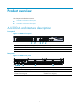
Product overview This chapter includes these sections: • A-U200-A architecture description • A-U200-S architecture description A-U200-A architecture description Front panel Figure 1 A-U200-A front panel (1) Copper Ethernet ports (GE0 through GE5) (2) Console port (3) USB interface (4) CF card eject button (5) CF card slot Rear panel Figure 2 A-U200-A rear panel (1) Grounding terminal and mark (2) “OPEN BOOK” mark (3) AC power switch (ON/OFF) (4) AC power receptacle (5) Slot1 (with an NSQ1GT2U
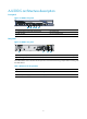
A-U200-S architecture description Front panel Figure 3 A-U200-S front panel (1) Copper Ethernet ports (GE0 through GE4) (2) Console port (3) USB interface (4) CF card eject button (5) CF card reader Rear panel Figure 4 A-U200-S rear panel (1) AC power receptacle (2) Slot (with a 2GE interface module installed in this diagram) (3) Grounding terminal and mark (4) “OPEN BOOK” mark The OPEN BOOK mark indicates that the operator must read the following chapters before working with the UTM device: Tabl
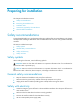
Preparing for installation This chapter includes these sections: • Safety recommendations • Examining the installation site • Installation tools • Accessories supplied by the UTM device • Checklist before installation Safety recommendations To avoid possible bodily injury and equipment damage, read the safety recommendations in this chapter carefully before installing a UTM device. The recommendations do not cover every possible hazardous condition.
• Do not work alone when the UTM device has power. • Always check that the power has been disconnected. Safety with laser • Do not stare into the optical port or fiber connector because the laser light emitted from the optical fiber may hurt your eyes. • Install a dust plug on the transceiver module to avoid damage to the transceiver module. Examining the installation site The UTM device can only be used indoors.
Altitude Table 4 Altitude requirements Item Altitude Operating altitude –60 m (–196.85 ft) to 3 km (1.86 miles) Storage altitude –60 m (–196.85 ft) to 4.5km(2.8 miles) Cleanness Dust buildup on the chassis may result in electrostatic adsorption, which causes poor contact of metal components and contact points, especially when indoor humidity is low. In the worst case, electrostatic adsorption can cause communication failure.
Figure 5 UTM device airflow • Make sure there is enough space (greater than 10 cm (3.94 in)) around the air intake and outlet vents on the UTM device for good ventilation. • Make sure the installation site has a good cooling system. ESD prevention To prevent electrostatic discharge (ESD), note the following guidelines: • Make sure that the UTM device and the floor are well grounded. • Take dust-proof measures for the equipment room. • Maintain the humidity and temperature at a proper level.
Figure 6 Use an ESD-preventive wrist strap 1 2 3 (1) ESD-preventive wrist strap (2) Lock (3) Alligator clip CAUTION: • Check the resistance of the ESD-preventive wrist strap for safety. The resistance reading should be in the range of 1 to 10 megohm (Mohm) between human body and the ground. • No ESD-preventive wrist strap is provided with the HP UTM device. Prepare it yourself.
• Install a lightning arrester at the input end of the power supply to enhance the lightning protection capability of the power supply. Rack-mounting Before mounting the UTM device in a standard 19-inch rack, adhere to the following requirements: • The rack is sturdy enough to support the UTM device and installation accessories.
Checklist before installation Table 7 Checklist before installation Item Requirements • There is a minimum clearance of 10 cm (3.9 in) around Ventilation the inlet and exhaust vents for heat dissipation of the UTM device chassis. • A ventilation system is available at the installation site. Operating temperature 0°C to 45°C (32°F to 113°F) Operating humidity 10% to 95% Cleanness Dust concentration ≤ 3 × 10⁴ particles/m3 • The equipment and floor are well grounded.
Item Requirements Safety precautions • The UTM device is far away from any moist area and heat source. • The emergency power switch in the equipment room is located.
Installing the UTM device This chapter includes these sections: • Installation flow • Installing the UTM device in a 19-inch rack • Grounding the UTM device • Installing interface modules • Installing a CF card • Connecting Ethernet cables • Connecting a power cord Installation flow Figure 7 HP A-U200-A/A-U200-S UTM device installation flow Start Install the UTM to a 19' rack Ground the UTM Install an interface module Install a CF card Connect Ethernet cables Connect the power cord End
Figure 8 Install cage nuts Step2 Install the mounting brackets to both sides of the front panel. Figure 9 Install the mounting brackets to both sides of the front panel Step3 Supporting the UTM device bottom with one hand, push the UTM device into the rack horizontally. Step4 Fix the UTM device horizontally by fastening the front mounting brackets at both sides to the rack with appropriate pan head screws.
Grounding the UTM device WARNING! Correctly connecting the UTM device grounding cable is crucial to lightning protection and EMI protection. Follow these steps to connect the grounding cable: Step1 Remove the grounding screw from the rear panel of the UTM device chassis. Step2 Attach the grounding screw to the OT terminal of the grounding cable. Step3 Use a screwdriver to fasten the grounding screw into the grounding screw hole.
Step3 Use a screwdriver to fasten the captive screws on the 2GE interface module. Figure 12 Install a 2GE interface module Installing an NSQ1GT2UA0 or NSQ1GP4U0 interface module The A-U200-A supports NSQ1GT2UA0 and NSQ1GP4U0 interface modules. The installation procedure of the two interface modules are the same. This section takes an NSQ1GP4U0 interface module for example.
Installing a CF card CAUTION: The UTM device supports only HP-provided CF cards, and does not guarantee compatibility with any other CF cards. Follow these steps to install a CF card: Step1 Push the CF card eject button all the way into the slot, and make sure that the button does not project from the panel. Step2 Insert the CF card into the slot following the direction shown in Figure 14, and make sure it does not project from the slot.
Connecting an optical fiber Before connecting an optical fiber to the SFP port of an NSQ1GP4U0 interface module, you must install a transceiver module to the SFP port, and then insert a LC fiber connector to the transceiver module. WARNING! When connecting an optical fiber, note the following guidelines: • Never bend or curve a fiber when connecting it. After a fiber is installed well, the bend radius must be not less than 10 cm (3.94 in). • Keep the fiber end clean.
Figure 16 Install the transceiver module Step3 Remove the dust cap from the transceiver module and the protective caps from the fibers. Step4 Plug the LC connectors on one end of the fiber cable into the Rx and Tx ports, and plug the LC connectors on the other end to the Tx and Rx ports on the peer device, as shown in Figure 17. Figure 17 Connect the fiber connectors Step5 Check the LED of the fiber port when you power on the UTM device.
Figure 18 Connect an AC power cord to the UTM device (A-U200-A for example) 18
Logging in to the UTM device and configuring basic settings This chapter includes these sections: • Logging in to the UTM device through the console port • Powering on the UTM device • Logging in to the UTM device through Telnet • Logging in to the UTM device through a web browser • Performing basic settings for the UTM device This chapter describes only the commonly used methods for logging in to the UTM device.
Figure 19 Connect the console cable CAUTION: • When you connect a PC to a powered-on UTM device, connect the DB-9 connector of the console cable to the PC before connecting the RJ-45 connector to the UTM device. • When you disconnect a PC from a powered-on UTM device, disconnect the DB-9 connector of the console cable from the PC after disconnecting the RJ-45 connector from the UTM device.
Figure 20 Connection description of the HyperTerminal Step2 Type the name of the new connection in the Name text box and click OK. The following dialog box appears. Select the serial port to be used from the Connect using drop-down list. Figure 21 Set the serial port used by the HyperTerminal connection Step3 Click OK after selecting a serial port and the following dialog box appears. Set Bits per second to 9600, Data bits to 8, Parity to None, Stop bits to 1, and Flow control to None.
Figure 22 Set the serial port parameters NOTE: To use the default settings, click Restore Defaults. Step4 Click OK after setting the serial port parameters and the system enters the following interface.
Figure 23 HyperTerminal window Step5 Click Properties in the HyperTerminal window to enter the aaa Properties dialog box. Click the Settings tab, set the Emulation to VT100, and then click OK. Powering on the UTM device Checking before power-on Before powering on the UTM device, verify the following items: • The power cord and grounding cable are properly connected. • The power source matches that required by the UTM device.
Logging in to the UTM device through Telnet NOTE: For more information about the Telnet login, see the configuration guides for the UTM device. You can use the default information to log in to the A-U200-A/A-U200-S UTM device. The default login information includes: • Username: admin • Password: admin • IP address of port GigabitEthernet 0/0: 192.168.0.
Launch the web browser on the PC. Type 192.168.0.1 in the address bar and press Enter. The login dialog box appears, as shown in Figure 24. In this dialog box, enter your user name (admin), password (admin), verify code and click Login. Figure 24 Web login dialog box Then, the web interface of the UTM device appears. Performing basic settings for the UTM device This section describes the fast configuration by using the basic configuration wizard.
Figure 25 Basic configuration wizard: 1/6 Configuring the system name and user password Click Next on the first page of the basic configuration wizard to enter the basic information configuration page, as shown in Figure 26.
Figure 26 Basic configuration wizard: 2/6 (basic information) Table 8 Basic information configuration items Item Description Sysname Set the system name. By default, the system name of the UTM device is HP. Modify Current User Password Specify whether to modify the login password of the current user. New Password To modify the password of the current user, set the new password and the confirm password, and the two passwords must be identical.
Figure 27 Basic configuration wizard: 3/6 (service management) Table 9 Service management configuration items Item FTP Telnet Description Specify whether to enable FTP on the device. Disabled by default. Specify whether to enable telnet on the device. Disabled by default. Specify whether to enable HTTP on the device, and set the HTTP port number. Enabled by default.
Item Description Specify whether to enable HTTPS on the device, and set the HTTPS port number. HTTPS is the HTTP protocol that supports the Secure Sockets Layer (SSL) protocol. It can improve device security. Disabled by default. IMPORTANT: HTTPS • If the current user logged in to the web interface through HTTPS, disabling HTTPS or modifying the HTTPS port number will result in disconnection with the device; therefore, perform the operation with caution.
Table 10 Interface IP address configuration items Item Description Set the approach for obtaining the IP address, including: • None: The IP address of the interface is not specified, that is, the interface has no IP address. • Static Address: Specify the IP address for the interface IP Configuration manually; if you select this item, you need to specify both the IP address and the mask. • DHCP: The interface obtains an IP address automatically through the DHCP protocol.
Table 11 NAT configuration items Item Description Interface Select an interface on which the NAT configuration will be applied. Generally, it is the outgoing interface of the device. Specify whether to enable dynamic NAT on the interface. Dynamic NAT If dynamic NAT is enabled, the IP address of the interface will be used as the IP address of a matched packet after the translation. By default, dynamic NAT is disabled.
Figure 30 Basic configuration wizard: 6/6 This page lists all configurations you have made in the basic configuration wizard. Confirm the configurations. To modify your configuration, click Prev to go back to the previous page; if no modification is needed, click Finish to execute all configurations.
Hardware management and maintenance This chapter includes these sections: • Displaying detailed information about the UTM device • Displaying software and hardware version information of the UTM device • Displaying the electrical label information of the UTM device • Displaying the CPU usage of the UTM device • Displaying the memory usage of the UTM device • Displaying the CF card information • Displaying the operational status of the fans • Displaying the operational status of a power module
Driver :1.0 CPLD :2.0 The SubCard1 on Board0: Status :Normal Type :ETH82571-2GE CARD Hardware :B Driver :1.0 CPLD :1.0 Displaying software and hardware version information of the UTM device Use the display version command to display software and hardware version information of the UTM device. display version HP Comware Platform Software Comware Software, Version 5.20, Release 5116P18 Copyright (c) 2010-2011 Hewlett-Packard Development Company, L.P.
VENDOR_NAME :HP slot 1 DEVICE_NAME :NONE DEVICE_SERIAL_NUMBER:NONE MAC_ADDRESS :NONE MANUFACTURING_DATE :NONE VENDOR_NAME :HP Displaying the CPU usage of the UTM device Use the display cpu-usage command to display the CPU usage of a UTM device. display cpu-usage Unit CPU usage: 1% in last 5 seconds 1% in last 1 minute 1% in last 5 minutes Displaying the memory usage of the UTM device Use the display memory command to display the memory usage of a UTM device.
Displaying the operational status of the fans Use the display fan command to display the operational status of the fans. display fan Fan 1 State: Normal Table 13 Output description Field Fan Description 1 Number of the fan The fan state: • Normal—The fan is operating properly. • Absent—The fan is not in position. • Fault—The fan fails. State Displaying the operational status of a power module Use the display power command to display the operational status of a power module.
Field Description SlotNO Number of the slot holding the interface module Temperature Current temperature Lower limit Lower threshold Upper limit Upper threshold Displaying operational statistics of the UTM device When you perform routine maintenance or the system fails, you may need to display the operational information of each functional module for locating failures. Generally, you need to run the display commands one by one.
during the process. The safe saving mode is preferred in environments where a stable power supply is unavailable or remote maintenance is involved.
CAUTION: • If the main host software file is not specified, do not use the reboot command to reboot the UTM device. In this case, you should specify the main host software file first, and then reboot the UTM device. • The precision of the rebooting timer is 1 minute. One minute before the rebooting time, the device prompts “REBOOT IN ONE MINUTE” and reboots in one minute. • If you are performing file operations when the device is to be rebooted, the system does not execute the reboot command for security.
Replacement procedures This chapter includes these sections: • Safety recommendations • Replacing an interface module • Replacing a CF card • Replacing a transceiver module Safety recommendations 1. Always wear an ESD-preventive wrist strap or ESD-preventive gloves when maintaining the UTM device hardware. 2.
Figure 31 Remove an interface module Step3 If you do not install a new interface module in the slot, install the filler panel. To install an interface module, see the chapter “Installing the UTM device.” Replacing a CF card CAUTION: • To avoid hardware damage, do not remove the CF card when the UTM device is booting or the CF card LED is blinking. • To protect the CF card, place it into an antistatic bag. Follow these steps to replace a CF card: Step1 Make sure that the CF card LED is not blinking.
Figure 33 Press the eject button to eject the CF card Step4 Install a new CF card. For more information, see the chapter “Installing the UTM device.” Replacing a transceiver module NOTE: When replacing a transceiver module, make sure that the two transceiver modules connected by the same optical fiber have the same wavelength. WARNING! • Do not stare into the optical fibers. • When removing a transceiver module, do not touch the golden finger of the transceiver module.
Step4 Insert the dust cap to the removed transceiver module, and put the module into its original shipping materials. Step5 Install a new transceiver module. For more information, see the chapter “Installing the UTM device.
Troubleshooting This chapter includes these sections: • Power supply system failure • Fan failure • Configuration terminal problems • Password loss • Cooling system failure • Interface module failure NOTE: • The barcode stuck on the UTM device chassis contains production and servicing information. Before you return a faulty UTM device for serving, provide the barcode information of the UTM device to your local sales agent.
Configuration terminal problems If the configuration environment setup is correct, the configuration terminal displays boot information when the UTM device is powered on. If the setup is incorrect, the configuration terminal displays nothing or garbled text. No terminal display If the configuration terminal displays nothing when the UTM device is powered on, check the following items: • The power supply system works properly. • The console cable is properly connected.
When you set the password by using the set authentication password { cipher | simple } password command, follow these guidelines. • If the cipher keyword is specified, the password is stored in cipher text. You cannot view the password by using the display current-configuration command. • If the simple keyword is specified, the password is stored in plain text. You can use the display current-configuration command to view the password in the current configuration.
Cooling system failure When the temperature inside the UTM device exceeds 45°C (113°F), the cooling system may have failed. Follow these steps to troubleshoot the cooling system: Step1 Check whether the fans are running properly. Step2 Check whether the working environment of the UTM device is well ventilated.
Appendix A Technical specifications Dimensions and weight Table 15 Dimensions and weight Item Specification Dimensions (H × W × D), excluding feet and mounting brackets A-U200-A: 44.2 × 442 × 400 mm (1.74 × 17.40 × 15.75 in.) Weight (fully configured) A-U200-S: 43.6 × 300 × 260 mm (1.72 × 11.81 × 10.24 in.) A-U200-A: 5.9 kg (13.01 lb) A-U200-S: 2.22 kg (4.
Item Specification A-U200-A: 1.6A Maximum input current A-U200-S: 1.
Appendix B LEDs LEDs Figure 35 A-U200-A LEDs 1 4 3 2 6 5 Figure 36 A-U200-S LEDs Table 21 Description of A-U200-A/A-U200-S LEDs LED (green) (green) (green) Status Meaning Off The system is powered off or faulty. Slow blinking (at 1 Hz) The UTM device is operating normally as configured. Fast blinking (at 8 Hz) Software is being loaded or the system is not working. Off No interface module is in the slot or the interface module is faulty.
LED LINK (green) ACT (yellow) Status Meaning Off No link is present. On A link is present. Off No data is being received or transmitted. Blinking Data is being received or transmitted.
Appendix C Interface modules NOTE: • The UTM device does not support hot-swapping of interface modules. • The A-U200-A supports NSQ1GT2UA0 and NSQ1GP4U0 interface modules, and the A-U200-S supports 2GE interface module. 2GE interface module Introduction The 2GE interface module provides two RJ-45 copper ports.
Item Description Interface standards 802.3, 802.3u, 802.3ab Autosensing Interface type Frame formats Maximum transmission distance Rate and negotiation mode When working in the forced mode, Ethernet does not support MDI/MDIX autosensing. Ethernet_II Ethernet_SNAP 100 m (328.08 ft.
Interface cable The NSQ1GT2UA0 interface module can use either standard network cables or crossover cables. For how to connect an Ethernet twisted pair, see the chapter “Installing the UTM device.” NSQ1GP4U0 interface module Introduction The NSQ1GP4U0 interface module provides four SFP fiber ports.
Item Specification Central wavelength 850 nm 1310 nm 1310 nm 1550 nm 1550 nm Max. transmission distance 0.55 km (0.34 miles) 10 km (6.21 miles) 40 km (24.86 miles) 40 km (24.86 miles) 70 km (43.50 miles) Fiber type 62.5/125 μm multi-mode 9/125 μm single-mode 9/125 μm single-mode 9/125 μm single-mode 9/125 μm single-mode Interface cable The NSQ1GP4U0 interface module can work with SFP optical transceivers using optical fibers with LC-type connectors.
Appendix D AC power cables used in different countries or regions 10A AC power cables used in different countries or regions Table 26 10A AC power cables used in different countries or regions 1 2 Connect or type Code (Length) Countries or regions where the type of power cables conforms to local safety regulations and can be used legally I type 04041104 (3 m, i.e., 9.
F type 4 5 6 04041056 (3 m, i.e., 9.8 ft) Holland, Denmark, Sweden, Finland, Norway, Germany, France, Austria, Belgium, and Italy Indonesia, Turkey, Russia, and CIS Connector outline Power cable outline Connect or type Code (Length) Countries or regions where the type of power cables conforms to local safety regulations and can be used legally Other countries or regions using this type of power cables G type 04040890 (3 m, i.e., 9.8 ft) U.K.
7 8 9 Connector outline Power cable outline Connect or type Code (Length) Countries or regions where the type of power cables conforms to local safety regulations and can be used legally I type 04040888 (3 m, i.e., 9.8 ft) Australia Connector outline Power cable outline Connect or type Code (Length) Countries or regions where the type of power cables conforms to local safety regulations and can be used legally J type 04041119 (3 m, i.e., 9.
16A AC power cables used in different countries or regions Table 27 16A AC power cables used in different countries or regions 1 Connector type Code (Length) Countries or regions where the type of power cables conforms to local safety regulations and can be used legally I type 04043396 (3 m, i.e., 9.
F type 4 5 6 0404A061 (3 m, i.e., 9.8 ft) Holland, Denmark, Sweden, Finland, Norway, Germany, France, Austria, Belgium, and Italy Indonesia, Turkey, Russia, and CIS Connector outline Power cable outline Connector type Code (Length) Countries or regions where the type of power cables conforms to local safety regulations and can be used legally Other countries or regions using this type of power cables G type 0404A060 (3 m, i.e., 9.8 ft) U.K.
I type 0404A01A (3 m, i.e., 9.
Support and other resources Contacting HP For worldwide technical support information, see the HP support website: http://www.hp.
Conventions This section describes the conventions used in this documentation set. Command conventions Convention Description Boldface Bold text represents commands and keywords that you enter literally as shown. Italic Italic text represents arguments that you replace with actual values. [] Square brackets enclose syntax choices (keywords or arguments) that are optional. { x | y | ... } Braces enclose a set of required syntax choices separated by vertical bars, from which you select one.
Network topology icons Represents a generic network device, such as a router, switch, or firewall. Represents a routing-capable device, such as a router or Layer 3 switch. Represents a generic switch, such as a Layer 2 or Layer 3 switch, or a router that supports Layer 2 forwarding and other Layer 2 features. Port numbering in examples The port numbers in this document are for illustration only and might be unavailable on your device.
Index ACDEFGILNPRS A G Accessories supplied by the UTM device,8 Grounding the UTM device,13 A-U200-A architecture description,1 I A-U200-S architecture description,2 Installation flow,11 C Installation tools,8 Checklist before installation,9 Installing a CF card,15 Configuration terminal problems,45 Installing interface modules,13 Connecting a power cord,17 Installing the UTM device in a 19-inch rack,11 Connecting Ethernet cables,15 Interface module failure,47 Contacting HP,62 L Conventi
Safety recommendations,40 Saving the running configuration of the UTM device,37 Safety recommendations,3 Storages,48 66