
Specifications

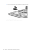

4. Turn the computer right-side up, with the front toward you.
5. Open the computer as far as possible.
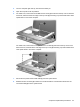
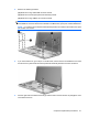
6. On model 2133, remove the Torx8 T8M2.5×10.0 screw (1) that secures the top cover to the base
enclosure, and then lift the rear edge of the top cover (2) and swing it up and forward until it rests
upside down in front of the computer.
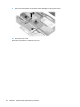
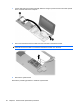
On model 2140, remove the four Phillips PM2.0×7.0 screws (1) that secure the top cover to the
base enclosure, and then lift the rear edge of the top cover (2) and swing it up and forward until it
rests upside down in front of the computer.
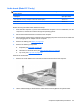
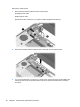
7. Disconnect the power switch board cable (1) from the system board.
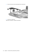
8. Release the ZIF connector (2) to which the TouchPad cable is connected and disconnect the
TouchPad cable (3) from the system board.
Component replacement procedures 53