HP 2533t Mobile Thin Client End-User Reference Guide
© Copyright 2008 Hewlett-Packard Development Company, L.P. Windows is a U.S. registered trademark of Microsoft Corporation. SD Logo is a trademark of its proprietor. The information contained herein is subject to change without notice. The only warranties for HP products and services are set forth in the express warranty statements accompanying such products and services. Nothing herein should be construed as constituting an additional warranty.
Safety warning notice WARNING! To reduce the possibility of heat-related injuries or of overheating the computer, do not place the computer directly on your lap or obstruct the computer air vents. Use the computer only on a hard, flat surface. Do not allow another hard surface, such as an adjoining optional printer, or a soft surface, such as pillows or rugs or clothing, to block airflow.
iv Safety warning notice
Table of contents 1 Notebook tour Identifying the hardware ....................................................................................................................... 1 Top components .................................................................................................................. 1 Pointing devices .................................................................................................. 1 Lights .........................................................................
Initiating Standby (fn+f3) .................................................................................................... 20 Switching the screen image (fn+f4) ................................................................................... 20 Viewing battery charge information (fn+f8) ........................................................................ 20 Decreasing screen brightness (fn+f9) ................................................................................
Using multimedia software ................................................................................................. 40 Preventing playback disruptions ........................................................................................ 40 Observing the copyright warning ....................................................................................... 41 7 Wireless About integrated wireless devices .............................................................................................
11 Drives Identifying installed drives .................................................................................................................. 62 Handling drives ................................................................................................................................... 62 Using optical drives (select models only) ........................................................................................... 63 Inserting an optical disc (CD or DVD) .............................
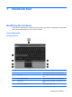
1 Notebook tour Identifying the hardware Components included with the computer may vary by region and model. The illustrations in this chapter identify the standard features on most computer models. Top components Pointing devices Component Description (1) Left TouchPad button* Functions like the left button on an external mouse. (2) TouchPad* Moves the pointer and selects or activates items on the screen. (3) Left pointing stick button* Functions like the left button on an external mouse.
(6) Right pointing stick button* Functions like the right button on an external mouse. (7) TouchPad scroll zone Scrolls up or down. (8) Right TouchPad button* Functions like the right button on an external mouse. *This table describes factory settings. To view or change pointing device preferences, select Start > Control Panel > Printers and Other Hardware > Mouse. Lights Component Description (1) ● On: The computer is on. ● Blinking: The computer is in Standby.
Component Description (6) ● Turquoise: Computer sound is on. ● Amber: Computer sound is off. ● Amber: A battery is charging. ● Turquoise: A battery is close to full charge capacity. ● Blinking amber: A battery that is the only available power source has reached a low battery level. When the battery reaches a critical battery level, the battery light begins blinking rapidly.
Component Description If the computer has stopped responding and Windows® shutdown procedures are ineffective, press and hold the power button for at least 5 seconds to turn off the computer. To learn more about your power settings, right-click the Power Meter icon in the notification area, and then click Adjust Power Properties (2) Info button Launches Info Center. (3) Internal display switch Turns off the display if the display is closed while the power is on.
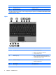
Component Description (2) fn key Executes frequently used system functions when pressed in combination with a function key or the esc key. (3) Windows logo key Displays the Windows Start menu. (4) Windows applications key Displays a shortcut menu for items beneath the pointer. (5) Embedded numeric keypad keys Can be used like the keys on an external numeric keypad. (6) Function keys Execute frequently used system functions when pressed in combination with the fn key.
Front components Component Description (1) ● Blue: An integrated wireless device, such as a wireless local area network (WLAN) device, is on. ● Off: All wireless devices are off. ● On: The computer is on. ● Blinking: The computer is in Standby. ● Off: The computer is off. ● Amber: A battery is charging. ● Turquoise: A battery is close to full charge capacity. ● Blinking amber: A battery that is the only available power source has reached a low battery level.
Right-side components Component Description (1) PC Card slot* Supports optional Type I and Type II 32-bit (CardBus) or 16-bit PC Cards. (2) SD Card Reader* Supports the Secure Digital (SD) Memory Card and MultiMediaCard (MMC) optional digital card formats. (3) Audio-out (headphone) jack Produces sound when connected to optional powered stereo speakers, headphones, ear buds, a headset, or television audio.
Left-side components NOTE: Refer to the illustration that most closely matches your computer. Component Description (1) Power connector Connects an AC adapter. (2) RJ-11 (modem) jack Connects a modem cable. (3) Powered USB port* Provides power to an external device if used with a powered USB cable. (4) USB port* Connects an optional USB device. (5) Vent Enables airflow to cool internal components. *For information regarding the status of the USB ports, contact your network administrator.
Component Description (5) Reads an optical disc. Optical drive (select models only) *For information regarding the status of the USB port, contact your network administrator. Rear components Components Description (1) RJ-45 (network) jack Connects a network cable. (2) Security cable slot Attaches an optional security cable to the computer. NOTE: The security cable is designed to act as a deterrent, but it may not prevent the computer from being mishandled or stolen.
Bottom components Component Description (1) Speaker Produces sound. (2) Memory module compartment Contains a memory module slot and a WLAN module slot. CAUTION: To prevent an unresponsive system, replace the wireless module only with a wireless module authorized for use in the computer by the governmental agency that regulates wireless devices in your country or region. If you replace the module and then receive a warning message, remove the module to restore computer functionality.
Wireless antennae Wireless antennae send and receive signals from one or more wireless devices. These antennae are not visible from the outside of the computer. NOTE: For optimal transmission, keep the areas immediately around the antennae free from obstructions. To see wireless regulatory notices, refer to the section of the Regulatory, Safety and Environmental Notices that applies to your country or region. These notices are located in the printed Getting Started guide.
Identifying the labels The labels affixed to the computer provide information you may need when you troubleshoot system problems or travel internationally with the computer: ● Service tag—Provides important information including the following: the product brand and series name, serial number (s/n), and product number (p/n) of your computer. ◦ Product name (1). This is the product name affixed to the front of your computer. ◦ Serial number (s/n) (2).
2 Enhanced Write Filter The Enhanced Write Filter (EWF) provides a secure environment for your computer by protecting it from undesired flash memory writes. In order to save changes to your system configuration settings, you must commit your changes in the EWF. Otherwise, the new settings will be lost when the computer is shut down or restarted. NOTE: For additional information on the EWF, see your network administrator.
3 Applications Citrix Program Neighborhood Citrix Program Neighborhood is a feature of ICA introduced with MetaFrame 1.8 that enables users to connect to MetaFrame and WinFrame servers and published applications. Program Neighborhood allows complete administrative control over application access and provides a seamless desktop integration. For additional information on the ICA client application, go to the Citrix Corporation Web site at http://www.citrix.com.
HP PC Session Allocation Manager (SAM) Client The Consolidated Client Infrastructure (CCI) solution from HP centralizes computing and storage resources into easily managed, highly secure data centers, while providing end users the convenience and familiarity of a traditional environment. Additionally, companies have long used server-based computing (SBC) to create virtual instances of desktop applications on a server that multiple remote users can access.
HP DHCP Settings Update Client The HP DHCP Settings Update Client is a utility located in the Control Panel. It allows an IT Administrator to apply settings to an HP XP Embedded operating system. The settings are applied through an .ini file that uses a subset of parameters from Microsoft’s sysprep.inf as well as several XPe/HP-specific keys. XPePrep can run by specifying a local .
Microsoft Internet Explorer Version 7.0 of the Microsoft Internet Explorer browser is installed locally on the computer. The Internet options settings for the browser have been preselected at the factory to limit writing to the flash memory. These settings should not be modified. You can access another browser through an ICA or RDP account if you need more browser resources. Service Pack 2 improves Microsoft Internet Explorer 7.
4 Keyboard Using pointing devices Setting pointing device preferences Use Mouse Properties in Windows to customize settings for pointing devices, such as button configuration, click speed, and pointer options. To access Mouse Properties, select Start > Control Panel > Printers and Other Hardware > Mouse. Using the TouchPad To move the pointer, slide your finger across the TouchPad surface in the direction you want the pointer to go.
Using hotkeys Hotkeys are combinations of the fn key (1) and either the esc key (2) or one of the function keys (3). The icons on the f3, f4, and f8 through f10 keys represent the hotkey functions. Hotkey functions and procedures are discussed in the following sections. Function Hotkey Display system information. fn+esc Initiate Standby. fn+f3 Switch the image. fn+f4 Display battery information fn+f8 Decrease screen brightness. fn+f9 Increase screen brightness.
Initiating Standby (fn+f3) Press fn+f3 to initiate Standby. When Standby is initiated, the power lights blink and the screen clears. Your computer is disconnected from the network. CAUTION: To reduce the risk of information loss, save your work before initiating Standby. The computer must be on before you can initiate Standby. To exit Standby, press the power button or any key on the keyboard. NOTE: In all Windows operating system windows, references to the Sleep button apply to the fn+f3 hotkey.
Using the HP Quick Launch Buttons The HP Quick Launch Buttons enable you to quickly open programs, files, or Web sites you use frequently. You can use the factory settings, which are described in the following table. Or you can reprogram the buttons by opening the Q Menu in the Quick Launch Buttons control panel. The Quick Launch Buttons include the info button (1) and the presentation button (2). The following table describes the factory settings for the Quick Launch Buttons.
Accessing the Quick Launch Buttons control panel The Q Menu in the Quick Launch Buttons control panel enables you to set your own preferences for the info button and the presentation button. Both buttons can be used to launch frequently used programs. You can open the Quick Launch Buttons control panel in any of the following ways: ● Select Start > Control Panel > Printers and Other Hardware > Quick Launch Buttons.
Using the keypads The computer has an embedded numeric keypad and also supports an optional external numeric keypad or an optional external keyboard that includes a numeric keypad. Component Description (1) fn key Executes frequently used system functions when pressed in combination with a function key or the esc key. (2) Num lock light On: Num lock is on. (3) Embedded numeric keypad Can be used like the keys on an external numeric keypad.
Switching key functions on the embedded numeric keypad You can temporarily alternate the functions of keys on the embedded numeric keypad between their standard keyboard functions and their keypad functions by using the fn key or the fn+shift key combination. ● To change the function of a keypad key to keypad functions while the keypad is disabled, press and hold the fn key while pressing the keypad key.
5 Power Power control and light locations The following illustration and table identify and describe the power control and light locations. Component Description (1) ● When the computer is off, press the button to turn on the computer. ● When the computer is on, press the button to turn off the computer. ● When the computer is in Standby, press the button briefly to exit Standby.
Component Description If the computer has stopped responding and Windows shutdown procedures are ineffective, press and hold the power button for at least 5 seconds to turn off the computer. To learn more about your power settings, right-click the Power Meter icon in the notification area, and then click Adjust Power Properties. (2) Power lights* (2) ● On: The computer is on. ● Blinking: The computer is in Standby. ● Off: The computer is off.
If the computer is unresponsive and you are unable to use the preceding shutdown procedures, try the following emergency procedures in the sequence provided: ● Press and hold the power button for at least 5 seconds. ● Disconnect the computer from external power and remove the battery. Setting power options Using power-saving states The computer has one power-saving state enabled at the factory: Standby. When Standby is initiated, the power lights blink and the screen clears.
Using the battery meter The battery meter is located in the notification area, at the far right of the taskbar. The battery meter allows you to quickly access power settings, view remaining battery charge, and select a different power plan: ● To display the percentage of remaining battery charge and the current power plan, move the pointer over the battery meter icon. ● To access Power Options, or to change the power plan, click the battery meter icon and select an item from the list.
You can keep a battery in the computer or in storage, depending on how you work. Keeping the battery in the computer whenever the computer is plugged into AC power charges the battery and also protects your work in case of a power outage. However, a battery in the computer slowly discharges when the computer is off and unplugged from external power.
2. Insert the battery into the battery bay (1) until it is seated. The battery release latches (2) automatically lock the battery into place. To remove the battery: 30 1. Turn the computer upside down on a flat surface, with the battery bay toward you. 2. Slide the left battery release latch (1) until it locks into place. 3. Slide the right battery release latch (2) to release the battery. 4. Remove the battery (3).
Charging a battery WARNING! Do not charge the computer battery while you are onboard aircraft. The battery charges whenever the computer is plugged into external power through an AC adapter, an optional power adapter, or an optional docking device. The battery charges whether the computer is off or in use, but it charges faster when the computer is off. Charging may take longer if a battery is new, has been unused for 2 weeks or more, or is much warmer or cooler than room temperature.
Resolving a low battery level CAUTION: To reduce the risk of losing information when the computer reaches a critical battery level, do not restore power until the power lights turn off. Resolving a low battery level when external power is available ▲ Connect one of the following devices: ● AC adapter ● Optional docking device ● Optional power adapter Resolving a low battery level when a charged battery is available 1. Turn off the computer. 2.
Conserving battery power ● Select low power-use settings through Power Options. ● Turn off wireless and local area network (LAN) connections and exit modem applications when you are not using them. ● Disconnect external devices that are not plugged into an external power source, when you are not using them. ● Stop, disable, or remove any external media cards that you are not using. ● Use the fn+f9 and fn+f10 hotkeys to adjust screen brightness as needed.
Using external AC power External AC power is supplied through one of the following devices: WARNING! To reduce potential safety issues, use only the AC adapter provided with the computer, a replacement AC adapter provided by HP, or a compatible AC adapter purchased from HP. ● Approved AC adapter ● Optional docking device Connect the computer to external AC power under any of the following conditions: WARNING! Do not charge the computer battery while you are onboard aircraft.
3. Plug the other end of the power cord into an AC outlet (3).
6 Multimedia Using multimedia hardware Using the audio features The following illustration and table describe the audio features of the computer. 36 Component Description (1) Volume mute button Mutes and restores computer sound. (2) Internal microphone Records sound. (3) Volume scroll zone Adjusts speaker volume. Slide your finger to the left to decrease volume and to the right to increase volume.
Using the audio-in (microphone) jack The computer is equipped with a stereo (dual-channel) microphone jack that supports an optional stereo array or monaural microphone. Using sound recording software with external microphones allows for stereo recordings. When connecting a microphone to the microphone jack, use a microphone with a 3.5-mm plug. Using the audio-out (headphone) jack WARNING! To reduce the risk of personal injury, adjust the volume before putting on headphones, earbuds, or a headset.
Adjusting the volume You can adjust the volume using the following controls: ● ● Computer volume buttons: ◦ Volume mute button ◦ Volume scroll zone Windows volume control: a. Click the Volume icon in the notification area, at the far right of the taskbar. b. Increase or decrease the volume by moving the slider up or down. Select the Mute check box to mute the volume. – or – a. Double-click the Volume icon in the notification area. b.
Using the video features Using the external monitor port The external monitor port connects an external display device, such as an external monitor or a projector, to the computer. ▲ To connect a display device, connect the device cable to the external monitor port. NOTE: If a properly connected external display device does not display an image, press fn+f4 to transfer the image to the device.
Using multimedia software The computer includes preinstalled multimedia software. Depending on the hardware and software included with the computer, you can play digital media, including audio and video CDs, audio and video DVDs, and Internet radio. NOTE: For information about using software included with the computer, refer to the software manufacturer's instructions, which may be provided on disc, in the software Help, or on the software manufacturer's Web site.
Observing the copyright warning It is a criminal offense, under applicable copyright laws, to make unauthorized copies of copyrightprotected material, including computer programs, films, broadcasts, and sound recordings. Do not use this computer for such purposes.
7 Wireless About integrated wireless devices Wireless technology transfers data across radio waves instead of wires. Your computer may be equipped with a wireless local area network (WLAN) device. This device connects the computer to wireless local area networks (commonly referred to as Wi-Fi networks, wireless LANs, or WLANs) in corporate offices, your home, and public places such as airports, restaurants, coffee shops, hotels, and universities.
NOTE: The terms wireless router and wireless access point are often used interchangeably. ● A large-scale WLAN, such as a corporate or public WLAN, typically uses wireless access points that can accommodate a large number of computers and accessories and can separate critical network functions.
Connecting to a WLAN To connect to a WLAN, follow these steps: 1. Verify that the WLAN device is turned on. If it is on, the wireless light is on. If the wireless light is off, press the wireless button. 2. Open Connect to a Network by selecting Start > Network Connections. 3. Double-click your wireless network in the list. 4. Type the encryption key. NOTE: You must commit these changes in order for them to be saved. Refer to Chapter 2, “Enhanced Write Filter,” for additional information.
8 Modem and LAN Using a modem The modem must be connected to an analog telephone line using a 6-pin, RJ-11 modem cable (purchased separately). In some countries, a country-specific modem cable adapter is also required. Jacks for digital PBX systems may resemble analog telephone jacks, but they are not compatible with the modem. WARNING! Connecting the internal analog modem to a digital line can permanently damage the modem.
2. Plug the modem cable into the RJ-11 telephone wall jack (2). Connecting a country-specific modem cable adapter Telephone jacks vary by country. To use the modem and the modem cable outside the country in which you purchased the computer, you must obtain a country-specific modem cable adapter. To connect the modem to an analog telephone line that does not have an RJ-11 telephone jack, follow these steps: 46 1. Plug the modem cable into the modem jack (1) on the computer. 2.
Selecting a location setting Viewing the current location selection To view the current location setting for the modem, follow these steps: 1. Select Start > Control Panel. 2. Click Date, Time, Language, and Regional Options. 3. Click Regional and Language Options. 4. Your location is displayed under Location. NOTE: You must commit these changes in order for them to be saved. Refer to Chapter 2, “Enhanced Write Filter,” for additional information.
Adding new locations when traveling By default, the only location setting available to the modem is a location setting for the country in which you purchased the computer. As you travel to different countries, set the internal modem to a location setting that meets the operating standards of the country in which you are using the modem. As you add new location settings, they are saved by the computer so that you can switch among settings at any time. You can add multiple location settings for any country.
Solving travel connection problems If you experience modem connection problems when using the computer outside of the country in which you purchased it, try the following suggestions. ● Check the telephone line type. The modem requires an analog, not a digital, telephone line. A line described as a PBX line is usually a digital line. A telephone line described as a data line, fax machine line, modem line, or standard telephone line is usually an analog line. ● Check for pulse or tone dialing.
5. Click Modem. 6. Clear the check box for Wait for dial tone before dialing. 7. Click OK twice. NOTE: You must commit these changes in order for them to be saved. Refer to Chapter 2, “Enhanced Write Filter,” for additional information. Connecting to a local area network Connecting to a local area network (LAN) requires an 8-pin, RJ-45 network cable (purchased separately).
9 Security Protecting the computer NOTE: Security solutions are designed to act as deterrents. These deterrents may not prevent a product from being mishandled or stolen. Your computer is designed for security. All information is saved to the network and no user information can be stored on the computer. Additional security features provided with your computer can protect the computer and your data from a variety of risks.
Using passwords Most security features use passwords. Whenever you set a password, write down the password and store it in a secure location away from the computer. Note the following password considerations: ● Setup and power-on passwords are set in Computer Setup and are managed by the system BIOS. ● Windows passwords are set only in the Windows operating system. ● If you forget the setup password set in Computer Setup, you will not be able to access the utility.
Managing a setup password A setup password is set, changed, and deleted in Computer Setup. To set, change, or delete this password, follow these steps: 1. Open Computer Setup by turning on or restarting the computer, and then pressing f10 while the “F10 = ROM Based Setup” message is displayed in the lower-left corner of the screen. 2. Use the arrow keys to select Security > Setup password, and then press enter. 3.
Managing a power-on password A power-on password is set, changed, and deleted in Computer Setup. To set, change, or delete this password, follow these steps: 1. Open Computer Setup by turning on or restarting the computer, and then pressing f10 while the “F10 = ROM Based Setup” message is displayed in the lower-left corner of the screen. 2. Use the arrow keys to select Security > Power-On password, and then press enter. 3.
Installing a security cable NOTE: The security cable (purchased separately) is designed to act as a deterrent, but it may not prevent the computer from being mishandled or stolen. 1. Loop the security cable around a secured object. 2. Insert the key (1) into the cable lock (2). 3. Insert the cable lock into the security cable slot on the computer (3), and then lock the cable lock with the key. NOTE: Your computer may look different from the illustration.
10 Hardware upgrades Using a USB device Universal Serial Bus (USB) is a hardware interface that can be used to connect an optional external device, such as a USB keyboard, mouse, drive, printer, scanner, or hub. Devices can be connected to the computer or an optional docking device. Some USB devices may require additional support software, which is usually included with the device. For more information about device-specific software, refer to the manufacturer's instructions.
Removing a USB device CAUTION: To prevent damage to a USB connector, do not pull on the cable to remove the USB device. To remove a USB device, safely remove the device from the USB port. Using the expansion port The expansion port connects the computer to an optional docking device or expansion product, so that additional ports and connectors can be used with the computer. NOTE: The computer has only one expansion port. The term expansion port 3 describes the type of expansion port.
Using PC Cards NOTE: For information regarding the status of the PC Card slot, contact your network administrator. Inserting and removing a PC Card CAUTION: To prevent damage to the computer and external media cards, do not insert an ExpressCard into a PC Card slot. CAUTION: To prevent damage to the connectors: Use minimal force when inserting a PC Card. Do not move or transport the computer when a PC Card is in use. The PC Card slot may contain a protective insert.
2. Insert the card into the PC Card slot, and then push in on the card until it is firmly seated. NOTE: An inserted PC Card uses power even when idle. To conserve power, stop or remove a PC Card when it is not in use. To remove a PC Card, follow these steps: 1. Close all programs and complete all activities that are associated with the PC Card. NOTE: 2. To stop a data transfer, click Cancel in the operating system Copying window. Release and remove the PC Card: a. Press the PC Card eject button (1).
Using SD Card Reader cards Optional digital cards provide secure data storage and convenient data sharing. These cards are often used with digital media–equipped cameras and PDAs as well as with other computers. The SD Card Reader supports the following digital card formats: ● MultiMediaCard (MMC) ● Secure Digital (SD) Memory Card NOTE: For information regarding the status of the SD Card Reader, contact your network administrator.
Removing a digital card 1. Save your information and close all programs associated with the digital card. NOTE: 2. To stop a data transfer, click Cancel in the operating system Copying window. To eject the digital card, press in on the digital card (1), and then remove it from the slot (2).
11 Drives Identifying installed drives To view the drives installed on the computer, select Start > HP System Information. NOTE: Windows includes the User Account Control feature to improve the security of your computer. You may be prompted for your permission or password for tasks such as running utilities or changing Windows settings. Refer to Windows Help for more information. Handling drives Drives are fragile computer components that must be handled with care.
Using optical drives (select models only) An optical drive, such as a DVD-ROM drive, supports optical discs (CDs and DVDs). These discs store or transport information and play music and movies. DVDs have a higher storage capacity than CDs. All optical drives can read from optical discs, as described in the following table.
5. Gently press the disc (3) down onto the tray spindle until the disc snaps into place. 6. Close the disc tray. NOTE: After you insert a disc, a short pause is normal before playback begins. Removing an optical disc (CD or DVD) There are 2 ways to remove a disc, depending on whether the disc tray opens normally or not. When the disc tray opens 1. 64 Press the release button (1) on the drive bezel to release the disc tray, and then gently pull out the tray (2) until it stops.
2. Remove the disc (3) from the tray by gently pressing down on the spindle while lifting the outer edges of the disc. Hold the disc by the edges and avoid touching the flat surfaces. NOTE: 3. If the tray is not fully accessible, tilt the disc carefully as you remove it. Close the disc tray and place the disc in a protective case. When the disc tray does not open 1. Insert the end of a paper clip (1) into the release access in the front bezel of the drive. 2.
3. Remove the disc (3) from the tray by gently pressing down on the spindle while lifting the outer edges of the disc. Hold the disc by the edges and avoid touching the flat surfaces. NOTE: If the tray is not fully accessible, tilt the disc carefully as you remove it. 4. 66 Close the disc tray and place the disc in a protective case.
A Routine care Cleaning the display CAUTION: To prevent permanent damage to the computer, never spray water, cleaning fluids, or chemicals on the display. To remove smudges and lint, frequently clean the display with a soft, damp, lint-free cloth. If the screen requires additional cleaning, use premoistened antistatic wipes or an antistatic screen cleaner.
CAUTION: Avoid exposing a drive to magnetic fields. Security devices with magnetic fields include airport walk-through devices and security wands. Security devices that use x-rays to check luggage moving on conveyor belts will not damage drives. ● If you plan to use the computer during a flight, check with the airline in advance. In-flight computer use is at the discretion of the airline.
Index A AC adapter, connecting 34 administrator password 52 airport security devices 62 antennae 11 applications key, Windows 5 audio features 36 audio-in (microphone) jack 7, 36, 37 audio-out (headphone) jack 7, 36, 37 B battery charging 31 conserving power 33 disposing 33 inserting 29 low battery levels 31 removing 29 storing 33 battery bay, identifying 10 battery charge information 20 battery light 26, 31 battery light, identifying 3, 6 battery power 28 battery release latches 10, 29 battery temperature
decreasing screen brightness 20 description 19 displaying system information 19 increasing screen brightness 20 initiating Standby 20 switching screen image 20 using 19 HP DHCP Settings Update Client 16 HP ThinState Capture 16 hubs 56 I image capture 16 info button identifying 4 internal display switch, identifying 4 internal microphone, identifying 5, 36 Internet connection setup 43 J jacks audio-in (microphone) 7, 36, 37 audio-out (headphone) 7, 36, 37 RJ-11 (modem) 8 RJ-45 (network) 9 K keyboard hotkeys,
conserving 33 control and light locations 25 power button identifying 3, 25 power connector, identifying 8 power light identifying 2, 26 power light, identifying 6 powered USB port, identifying 8 presentation button identifying 4 product name and number, computer 12 programs, using 40 projector, connecting 39 protecting playback 40 public WLAN connection 44 Q Quick Launch Buttons 21 Quick Launch Buttons control panel 22 R readable media 27 regulatory information modem approval label 12 regulatory label 12 w