
HP ProBook 450 G4 Notebook PC and HP ProBook 455 G4 Notebook PC - Maintenance and Service Guide

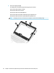


Display assembly
Description Spare part number
Display panel assembly, touch; models without WWAN
Touch display are only spared as entire hinge-ups. Individual components are not spared.
Non-touch displays are ONLY spared at the subcomponent level. For more information about display
components, see Display components on page 21.
907724-001
Display panel assembly, touch; models with WWAN 907725-001
This section describes removing components that require you to completely remove the display panel. For
more information about removing display components that do not require that you remove the assembly
from the computer, see Display subcomponents (bezel, webcam, panel) on page 48.
Before removing the display assembly, follow these steps:
1. Shut down the computer. If you are unsure whether the computer is o or in Hibernation, turn the
computer on, and then shut it down through the operating system.
2. Disconnect all external devices connected to the computer.
3. Disconnect the power from the computer by rst unplugging the power cord from the AC outlet, and
then unplugging the AC adapter from the computer.
4. Remove the following components:
a. Service door (see Service door on page 33).
b. Hard drive (see Hard drive on page 36)
c. Optical drive (Optical drive on page 34)
d. WLAN module (see WLAN/Bluetooth combo card on page 40)
e. WWAN module (see WWAN module on page 42)
f. Keyboard (see Keyboard on page 45)
g. Top cover (see Top cover on page 52)
h. Battery (see Battery on page 66)
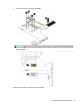
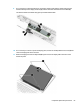
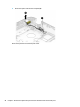
Remove the display assembly:
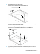
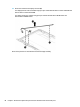
1. Position the computer upright on a at surface.
2. Disconnect the display cable from the system board (1).
3. Pull the wireless antennas through the hole in the computer (2), as applicable to your model.
4. Lift the conductive tape from atop the power connector cable and display hinge (3).
NOTE: When installing the display, be sure to replace the conductive tape atop the display hinge and
power connector cable. This tape is required to properly regulate electrostatic discharge.
5. Remove the 4 Phillips PM2.5×7.0 screws (4) from the display hinges.
82 Chapter 6 Removal and replacement procedures for Authorized Service Provider parts