
HP Z440, Z640, and Z840 Workstation Series - Maintenance and Service Guide
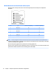

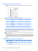
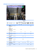
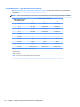

HP Z840 Workstation slot identication and description
Maximum power used by all slots must not exceed total system power and is subject to conguration
limitations.
Slot Type Mechanical compatibility Electrical compatibility
1 PCIe3 x4 x4 x4
2 PCIe3 x16 x16 x16
3 PCIe3 x8 x8 x8
4 PCIe3 x16 x16 x16
5 PCIe2 x8 x8 x4
5 PCIe3 x8 (CPU1) x8 x8
6 PCIe3 x16 x16 x16
7 PCIe2 x1 x1 x1
NOTE: The PCIe designators indicate the mechanical connector size and number of electrical PCIe lanes
routed to an expansion slot. For example, x16(8) means that the expansion slot is mechanically an x16 length
connector, with 8 PCIe lanes supported.
NOTE: Slots one and ve use open-ended PCIe connectors, so a PCIe x16 card can be inserted. This allows
the workstation to support more PCIe x16 expansion cards. An x16 card typically trains and runs at the
maximum lane width available by the expansion slot. The card runs at the reduced lane width, with a
corresponding performance decrease.
NOTE: A eighth slot opening in the chassis has no corresponding expansion connector on the system board.
This slot opening is provided for devices that do not require system board plug-in capability.
NOTE: It is normal for the expansion card retention clamp to have a slight (5-10 degree) angle when closed.
If the angle is greater than this, open the clamp and ensure that all cards are properly seated and all the
brackets are mated to the chassis, and then re-close the clamp.
56 Chapter 3 Component replacement information and guidelines