
HP ProBook 640 G2 Notebook PC, HP ProBook 645 G2 Notebook PC, HP ProBook 650 G2 Notebook PC and HP ProBook 655 G2 Notebook PC - Maintenance and Service Guide
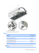

IMPORTANT: Make special note of each screw and screw lock size and location during removal and
replacement
Before removing the system board, follow these steps:
1. Shut down the computer.
2. Disconnect all external devices connected to the computer.
3. Disconnect the power from the computer by rst unplugging the power cord from the AC outlet and then
unplugging the AC adapter from the computer.
4. Remove the following components:
a. Service door (see Service door on page 37).
b. Battery (see Battery on page 38).
c. Hard drive (see Hard drive on page 39).
d. Solid-state drive (see Solid-state drive (select products only) on page 41).
e. WWAN module (see WWAN module (select products only) on page 42).
f. WLAN module (see WLAN module on page 44).
g. Optical drive (see Optical drive on page 46).
h. Keyboard (see Keyboard on page 48).
i. Hinge covers (see Hinge cover on page 55).
j. Base enclosure (see Base enclosure on page 57).
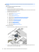
Remove the system board:
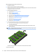
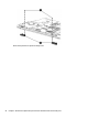
1. Disconnect the RTC battery cable (2) and the power button board cable (2).
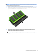
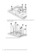
2. Loosen 3 P1 captive screws (1) on the fan, remove 4 M2x3L P1 screws (2) from the system board, and
remove 2 M2x3L screws from the ODD board (3).
60 Chapter 6 Removal and replacement procedures for Authorized Service Provider parts