
HP ProBook 640 G2 Notebook PC, HP ProBook 645 G2 Notebook PC, HP ProBook 650 G2 Notebook PC and HP ProBook 655 G2 Notebook PC - Maintenance and Service Guide

11. Optical drive (see Optical drive on page 46).
12. Keyboard (see Keyboard on page 48).
13. Hinge covers (see Hinge cover on page 55).
14. Base enclosure (see Base enclosure on page 57).
15. System board (see System board on page 59).
16. Fan/heat sink assembly (see Fan and heat sink assembly on page 61).
17. Top cover (see Top cover and TouchPad on page 65).
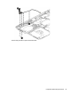
Remove the display assembly components:
1. Position the computer upright, with the front toward you.
2. Open the computer as far as possible.
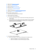
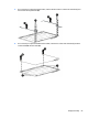
3. If it is necessary to replace the display bezel:
a. Close the computer, position it so you can access the bottom of the display, and then open the
computer slightly.
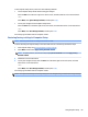
b. Flex the inside edges of the top edge (1), the left and right sides (2), and the bottom edge (3) of
the display bezel until the bezel disengages from the display enclosure. The display bezel is
available using spare part number 840658-001.
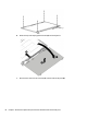
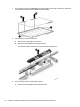
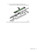
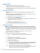
4. If it is necessary to replace the display panel:
a. Remove the four M2x3L P1 screws that secure the display panel to the display enclosure.
●
781959-001—35.6-cm (14.0-in), LED, AntiGlare display panel, UWVA
●
784476-001—35.6-cm (14.0-in), LED, AntiGlare display panel, SVA HD+
Display assembly 83