CMC AC Variable Speed Drive Series S 1 - 30 HP (230/46 (230/460V) Installation, Operation and Maintenance Instruction Read this manual carefully before installing, wiring, operating, servicing or inspecting the drive. Keep this manual within easy reach for quick reference.
Thank you for purchasing CMC Variable Frequency Drives ! SAFETY INSTRUCTIONS Always follow safety instructions to prevent accidents and potential hazards from occurring. In this manual, safety messages are classified as follows: WARNING CAUTION Improper operation may result in serious personal injury or death. Improper operation may result in slight to medium personal injury or property damage.
Operate the switches with dry hands. Otherwise, you may get an electric shock. Do not use the cable when its insulating tube is damaged. Otherwise, you may get an electric shock. Do not subject the cables to scratches, excessive stress, heavy loads or pinching. Otherwise, you may get an electric shock. CAUTION Install the inverter on a non-flammable surface. Do not place flammable material nearby. Otherwise, fire could occur. Disconnect the input power if the inverter gets damaged.
Environment Use the inverter under the following environmental conditions: Ambient temperature Relative humidity Storage temperature Location Altitude, Vibration Atmospheric pressure - 10 ~ 40 ℃ (non-freezing) 90% RH or less (non-condensing) - 20 ~ 65 ℃ Protected from corrosive gas, combustible gas, oil mist or dust Max. 1,000m above sea level, Max. 5.9m/sec2 (0.
Use an insulation-rectified motor or take measures to suppress the micro surge voltage when driving 400V class motor with inverter. A micro surge voltage attributable to wiring constant is generated at motor terminals, and may deteriorate insulation and damage motor. Before operating unit and prior to user programming, reset user parameters to default settings. Inverter can easily be set to high-speed operations, Verify capability of motor or machinery prior to operating unit.
CONTENTS USER SELECTION GUIDE (ACTIONMASTER SPECIFICATIONS) .....................................................................II CHAPTER 1 1.1 1.2 1.3 1.4 1.5 1.6 1.7 1.8 Inspection..........................................................................................................................................................1-2 Environmental Conditions ...............................................................................................................................1-2 Mounting....
6.6 Application Group [APP]..................................................................................................................................6-2 CHAPTER 7 7.1 7.2 7.3 7.4 7.5 7.6 Sub-A board ......................................................................................................................................................7-2 Sub-B Board ........................................................................................................................................
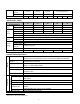
USER SELECTION GUIDE (ACtionMaster SPECIFICATIONS) 230V Class (1 ~ 30HP) Model Number SV xxx ACtionMaster - 2 008 015 022 037 055 075 110 150 185 220 2 3 5 7.5 10 15 20 25 30 Motor HP 1 Rating1 kW 0.75 1.5 2.2 3.7 5.5 7.5 11 15 18.5 22 Capacity2 [kVA] 1.9 3.0 4.5 6.1 9.1 12.2 17.5 22.9 28.2 33.
Max. Continuous Baking Time 5 seconds 5 seconds 15 seconds Controlled by Braking Unit 5 3 % ED 2 % ED 5 % ED 5 % ED Max. Duty Weight [lbs] 10.4 10.4 10.6 10.8 17.0 17.0 30.6 31.7 44.1 44.
Output Sig.
CHAPTER 1 - INSTALLATION 1.1 Inspection Inspect the inverter for any damage that may have occurred during shipping. Check the nameplate on the inverter. Verify the inverter unit is the correct one for the application. The numbering system for the inverter is as shown below. SV CMC Inverter Motor Capacity 008: 1 HP 185: 25 HP 015: 2 HP 220: 30 HP 022: 3 HP 300: 40 HP 037: 5 HP 370: 50 HP 055: 7.
Chapter 1 - Installation 1.4 Other Precautions Do not carry the inverter by the front cover. Do not install the inverter in a location where excessive vibration is present. Be cautious when installing on presses or moving equipment. The life span of the inverter is greatly affected by the ambient temperature. Install in a location where temperature are within permissible limits (- 10 ~ 40 ℃). The inverter operates at high-temperatures - install on a non-combustible surface.
Chapter 1 - Installation 1.5 Dimensions Frame # 1: 1 ~ 5 HP Frame # 2: 7.5 ~ 10 HP Frame HP 1 2 Frame # 1 3 5 7.5 Frame # 2 10 Model Number SV008ACtionMa ster-2/4 SV015ACtionMa ster-2/4 SV022ACtionMa ster-2/4 SV037ACtionMa ster-2/4 SV055ACtionMa ster-2/4 SV075ACtionMa ster-2/4 W1 W2 H1 H2 D1 150 (5.91) 130 (5.12) 284 (11.18) 269 (10.69) 156.5 (6.16) 200 (7.87) 180 (7.09) 355 (13.98) 340 (13.39) 182.5 (7.
Chapter 1 - Installation BLANK 1-4
Chapter 1 - Installation Frame # 3: 15 ~ 20 HP Frame # 4: 25 ~ 30 HP mm (inches) Frame Frame # 3 HP 15 20 25 Frame # 4 30 Model Number SV110ACtionMa ster-2/4 SV150ACtionMa ster-2/4 SV185ACtionMa ster-2/4 SV220ACtionMa ster-2/4 W1 W2 H1 H2 D1 250 (9.84) 230 (9.06) 385 (15.16) 370 (14.57) 201 (7.91) 304 (11.97) 284 (11.18) 460 (18.11) 445 (17.52) 234 (9.
Chapter 1 - Installation BLANK 1-6
Chapter 1 - Installation 1.
Chapter 1 - Installation 1.7 Power Terminals Type A Configuration: 1 ~ 5 HP (SV008ACtionMaster-2, SV015ACtionMaster-2, SV022ACtionMaster-2, SV037ACtionMaster-2, SV008ACtionMaster-4, SV015ACtionMaster-4, SV022ACtionMaster-4, SV037ACtionMaster-4) R S T G N B1 B2 U V W Type B Configuration: 7.
Chapter 1 - Installation 1.7.1 Type A Configuration As standard on the ACtionMaster inverter, this type of configuration has internal dynamic braking resistor of 3% ED. When an application requires more braking duty, an external dynamic braking resistor may be connected instead of the internal resistor. R S T G N B1 B2 U 3 Phase Power Input V W Motor Dynamic Braking Resistor Figure 1 – Type A Dynamic Braking Resistor Installation 1.7.
Chapter 1 - Installation 1.7.3 Type C Configuration A Dynamic Braking Unit or a DC Bus Choke or both of them may be added to ACtionMaster series inverters that have a Type A Configuration power terminal strip. Jumper Between P1 and P2 Must Be Removed in Order to Install a DC Bus Choke.
Chapter 1 - Installation 1.7.4 Wiring Power Terminals Wiring Precautions The internal circuits of the inverter will be damaged if the incoming power is connected and applied to output terminals (U, V, W). Use ring terminals with insulated caps when wiring the input power and motor wiring. Do not leave wire fragments inside the inverter. Wire fragments can cause faults, breakdowns, and malfunctions. For input and output, use wires with sufficient size to ensure voltage drop of less than 2%.
Chapter 1 - Installation Wires and Terminal Lugs Refer to the following table for wires, terminal lugs, and screws used to connect the inverter power input (R, S, T) and output (U, V, W). Inverter Capacity 200V Class 400V Class 1 ~ 3 HP 5 HP 7.5 HP 10 HP 15 HP 20 HP 25 HP 30 HP 1 ~ 5 HP 7.5 HP 10 HP 15 HP 20 HP 25 HP 30 HP Screw Torque8 (Kgf·cm)/lb-in Terminal Screw Size M3.5 M3.5 M4 M4 M5 M5 M6 M6 M3.
Chapter 1 - Installation 1.8 Control Terminals P1 30A Type 30C 30B Symbol Starting Contact Function Select FX RX JOG BX RST CM NC Analog frequency setting Input signal P1, P2, P3 VR V1 I Contact Output signal Analog 5G FM 30A 30C 30B AXA, AXC Comm. AXA AXC CN3 P2 JOG CM P3 CM Name FX RX NC BX RST VR I FM V1 5G Description Multi-Function Input 1, 2, 3 Forward Run Command Reverse Run Command Jog Frequency Reference Used for Multi-Function Input Terminal.
Chapter 1 - Installation 1.8.1 Wiring Control Terminals Wiring Precautions CM and 5G terminals are insulated to each other. Do not connect these terminals with each other and do not connect these terminals to the power ground. Use shielded wires or twisted wires for control circuit wiring, and separate these wires from the main power circuits and other high voltage circuits.
Chapter 1 - Installation 1.8.2 Keypad Connection Connect keypad to the keypad connector as illustrated below. The LCD output will not be displayed on the keypad if the keypad is not connected properly.
Chapter 1 - Installation Notes: 1-16
CHAPTER 2 - OPERATION The ACtionMaster series inverter has seven parameter groups separated according to their applications as indicated in the following table. The ACtionMaster series inverter provides two kinds of keypad. One is of 32-character alphanumeric LCD keypad and the other is of 7-Segment LED keypad. 2.
Chapter 2 - Operation 2.2 LCD Keypad LCD keypad can display up to 32 alphanumeric characters, and various settings can be checked directly from the display. The following is an illustration of the keypad. The Program Button is used to go into programming mode to change data. 32 character, back light, LCD display. The back light is adjustable. The Enter Button is used to enter changed data within a parameter.
Chapter 2 - Operation 2.2.1 LCD Keypad Display 3) Frequency Setting Source 2) Run/Stop Source 1) Parameter group 4) Output Current DRV¢ºT/K 00 STP 0.0 A 0.00 Hz 5) Parameter Code 7) Drive Output Frequency During Run, Command Frequency During Stop 6) Operating Status Displays 1) Parameter Group 2) Run/Stop Source 3) Frequency Setting Source 4) Output Current 5) Parameter Code 6) Operating Status 7) Drive Output Frequency Command Frequency Description Displays the parameter group.
Chapter 2 - Operation 2.2.2 Procedure for Setting Data (LCD Keypad) 1. Press [MODE] key until the desired parameter group is displayed. 2. Press [▲] or [▼] keys to move to the desired parameter code. If you know the desired parameter code, you can set the code number of each parameter group in “Jump code”, except DRV group. 3. Press [PROG] key to go into the programming mode, the cursor starts blinking. 4. Press [SHIFT/ESC] key to move the cursor to the desired digit. 5.
Chapter 2 - Operation 2.2.3 Parameter Navigation (LCD Keypad) The parameter group moves directly to DRV group by pressing [SHIFT/ESC] key in any parameter code. Drive Group FU1 Group FU2 Group I/O Group MODE DRV▶ T/K 0.0 A 00 STP 0.00 Hz MODE FU1▶ Jump code 00 1 ▶ ▶ ◀ ▶ ◀ ▶ ▶ ◀ ▶ I/O▶ V1 volt x2 04 10.00 V ▶ ◀ ▶ ◀ FU2▶ Last trip-5 05 ------- MODE I/O▶ V1 freq y2 05 60.
Chapter 2 - Operation 2.3 7-Segment Keypad * Parameter Group Display LEDs. 7-segment display [SHIFT] This button is used to move cursor across display in programming mode. [ESC] This button is used to move the program code to DRV 00 from any program code. Encoder knob Used to move you through parameter groups and parameter code. Also, used to change data by rotating knob. Run Button is used to run the drive. The motor direction is set in DRV 13. The Run LED blinks when the drive Accels or Decels.
Chapter 2 - Operation 2.3.1 7-Segment Keypad Display 1) Parameter Group DRV FU1 FU2 I / O EXT 2) Parameter Code and Operating Status 3) Output Frequency during run, Command Frequency during stop Display 1) Parameter Group 2) Parameter Code and Operating Status 3) Output Frequency, Command Frequency Description Displays the parameter groups of DRV, FU1, FU2, I/O, EXT, COM, APP groups.
Chapter 2 - Operation 2.3.2 Procedure for Setting Data (7-Segment Keypad) In DRV Group: 1. Rotate the encoder knob until the desired parameter code is displayed. 2. Press [PROG/ENT] key to go into the programming mode, then the display blinks. 3. Press [SHIFT/ESC] key to move the cursor to the desired digit. 4. Rotate the encoder knob to change the data. 5. Press [PROG/ENT] key to enter the changed data. In FUN1 Group: 1.
Chapter 2 - Operation 2.3.3 Parameter Navigation (7-Segment Keypad) The parameter group moves directly to DRV group by pressing [SHIFT/ESC] key in any parameter code.
Chapter 2 - Operation 2.4 Operation Method The ACtionMaster has several operation methods as shown below. Operation Method Operation using Keypad Operation using Control Terminals Operation using both Keypad and Control Terminals Operation using Option Boards Function Run/Stop command and frequency are set only through the keypad. Closing FX or RX terminal performs Run/Stop. Frequency reference is set through V1 or I or V1+I terminal. Run/Stop is performed by the keypad.
Chapter 2 - Operation Notes: 2-11
CHAPTER 3 - QUICK-START PROCEDURES These Quick-Start Up instructions are for those applications where: The user wants to get the ACtionMaster inverter started quickly The factory-preset values are suitable for the user application The factory-preset values are shown on the ‘Chapter 4 - Parameter List’. The ACtionMaster inverter is configured to operate a motor at 60Hz (base frequency).
Chapter 3 - Quick-Start Procedures 3.1 Operation using Keypad LCD Display 1. Apply AC power. DRV►T/K 00 STP 7-Segment Display 0.0 A 0.00Hz The DRV LED is ON. 2. 3. LCD: Press [▲] key three times. 7-Seg: Rotate the encoder knob until ‘03’ is displayed. DRV► Drive mode 03 Fx/Rx-1 LCD: Press [PROG] key. 7-Seg: Press[PROG/ENT] key. DRV► Drive mode 03 Fx/Rx-1 The DRV LED is turned ON. The PROG/ENT LED turned ON. 4. LCD: Press [▼] key one time. 7-Seg: Rotate the encoder knob left.
Chapter 3 - Quick-Start Procedures 3.2 Operation using Control Terminals LCD Display 1. 7-Segment Display Install a potentiometer on terminals V1, VR, 5G and connect wiring as shown below. 1 ㏀, 1/2 W P1 P2 P3 FX RX NC VR VI JOG CM CM BX RST 2. I FM 5G Apply AC power. DRV►T/K 00 STP 0.0 A 0.00Hz The DRV LED is ON. 3. Confirm that the DRV 03 is set at ‘Fx/Rx-1’. DRV► Drive mode 03 Fx/Rx-1 4. LCD: Press [▲] key to move DRV 04. 7-Seg: Rotate encoder knob until ‘04’ is displayed.
Chapter 3 - Quick-Start Procedures 3.3 Operation using Keypad and Control Terminals 3.3.1 Frequency set by External Source and Run/Stop by Keypad 1. Install a potentiometer on terminals V1, VR, 5G and connect wiring as shown below left. When a ‘4 to 20mA’ current source is used as the frequency reference, use terminals I and 5G as shown below right. DRV 04 must be set at V1. DRV 04 must be set at I.
Chapter 3 - Quick-Start Procedures 3.3.2 1. Frequency set by Keypad and Run/Stop by External Source. LCD Display Connect wiring as shown below. 7-Segment Display P1 P2 P3 FX RX NC VR VI JOG CM CM BX RST 2. I FM 5G Apply AC power. DRV►T/K 00 STP 0.0 A 0.00Hz The DRV LED is ON. 3. Confirm that the DRV 03 is set at ‘Fx/Rx-1’. DRV► Drive mode 03 Fx/Rx-1 4. Confirm that the DRV 04 is set at ‘Keypad-1’. DRV► 04 5. Press [SHIFT/ESC] key. DRV►T/K 00 STP 6. LCD: Press [PROG] key.
CHAPTER 4 - VARIOUS FUNCTION SETTING & DESCRIPTION 4.1 Function Setting 4.1.1 Basic function parameter setting It is the basic function setting. All settings are factory defaults unless users make change. It is recommended to use factory setting value unless the parameter change is necessary. 1) Common parameter setting The following table shows common parameter setting that should be checked before use but making change does not affect inverter control type.
Chapter 4 – Function Settings 3) V/F + PG control If FU2-39 [control mode] is set to V/F with PG (encoder) feedback using SUB-B or SUB-D boards, the control type is automatically changed to V/F + PG. The following parameters should be set accordingly to enable PG feedback using SUBB or SUB-D boards.
Chapter 4 – Function Settings FU2-40 Description No Motor constants calculation disabled All All constants can be measured in this code but different constants are tuned according to control mode type; For V/F, Slip compen , Sensorless_S, Sensorless_T: (No-load current, stator resistance, leakage inductance, stator inductance available) Note) Only no-load current can be calculated during V/F and Slip compensation.
Chapter 4 – Function Settings Before selecting Vector control mode, encoder setting should be done as indicated above. If the parameter value of actual motor is set in common setting, execute Auto-tuning before selecting vector control mode.
Chapter 4 – Function Settings 2) Sensorless vector control Related parameters for starting during Sensorless vector control when FU2-39 [Control Mode Selection] is set to 2 {Sensorless_S}. Status Code FU1-14 When starting I/O12~14 EXT2~4 Description Setting pre-excitation time Multi-function input terminal P1- P6 define 3) Vector control [Vector_SPD, Vector_TRQ] Related parameters for starting/ running/ stopping during Vector control when FU2-39 [Control Mode Selection] is set to 4 {Vector_SPD}.
Chapter 4 – Function Settings 5) Parameter initialize Parameter Name Code Description Software version FU2-79 Display the inverter software version Parameter Read/Write/Initialize/Write protection FU2-91 FU2-92 FU2-93 FU2-94 [FU2-91], [FU2-92]: Copying parameters from other inverter enabled [FU2-93]: Initializing parameters to factory setting values [FU2-94] : Parameter write disabled 6) Protection & fault detection level setting Parameter Name Electronic thermal Overload alarm and trip Stall p
Chapter 4 – Function Settings 8) Operation-starting method Parameter Name Code Description Starting method FU2-20 FU2-21 FU2-26 FU2-27 Motor starting method: [FU2-20] : Power-on run, [FU2-21] Restart after Fault Reset, [FU2-26] Number of Auto Restart Attempt [FU2-27] Delay Time Before Auto Restart See parameter description for more.
Chapter 4 – Function Settings 3) Auto sequence operation If I/O-50 [Auto (Sequence) Operation selection] is set to 1 {Auto-A} or 2 {Auto-B}, up to 5 sequences can be set with max of 8 steps (speed) in each sequence. Therefore, max 40 operating steps can be made. Two different types of auto sequence (A, B) operation are available.
Chapter 4 – Operation Examples 4.2 Operation Example Operation Example (1) V/F Control + Analog Voltage Input (V1) + Operation via Terminal (FX/RX) [Operation condition] -. Control mode : V/F control -. Frequency command : 50[Hz] analog input via V1 terminal -. Accel/Decel time : Accel – 15 [Sec], Decel – 25 [Sec] -.
Chapter 4 - Operation Examples Operation example (2) (V/F + PG) Control + operation (Run/Stop) via Keypad [Operation condition] -. Control mode: V/F + PG control -. Frequency command: 50[Hz] Digital input via Keypad -. Accel time : 15[sec], Decel time : 25 [sec] -. Drive mode : Run/Stop via Keypad -. Wiring block diagram when an Open Collector- type encoder is used.
Chapter 4 - Operation Examples Operation Example (3) 2nd motor operation [Operation condition] -. Control mode: V/F control -. 1st motor + 2nd motor Operation by exchange using [2nd Func] (Values can be set differently) -. Frequency command : Using Multi-speed 1st motor --- Apply 50[Hz] as main speed 2nd motor --- Apply 20[Hz] with P1 terminal set as multi-speed operation st -.
Chapter 4 - Operation Examples Operation Example (4) Sensorless_S Control + Multi-speed operation + Analog output (FM) [Operation condition] -. Control mode : Sensorless Speed control -. Frequency command : Multi-function input from SUB-A and 8 step speed operation (Multi-speed 7 + jog freq 1) -. Accel time : 5 [Sec], Decel time: 5 [Sec] -.
Chapter 4 - Operation Examples Operation Example (5) Vector_SPD Control [Operation condition] -. Control Mode : Vector_SPD Control, -. Encoder specification : Pulse number (1024), Line Drive type -. Freq command : set it 55[Hz] via KPD-1 -. Accel/Decel time : Accel – 15 [sec], Decel – 25 [sec], -.
Chapter 4 - Operation Examples Notes: 4-14
CHAPTER 5 - PARAMETER LIST 5.1 Drive Group [DRV] Code Description Keypad Display LCD Setting Range 7-Segment Adj. During Page Run Units Factory Default 0 to FU1-20 (Max. freq) 0.01 0.00 [Hz] Yes 6-2 0 to 6000 0.1 10.0 [sec] Yes 6-2 0.1 20.0 [sec] Yes 6-2 - Fx/Rx-1 No 6-2 - Keypad-1 No 6-2 Yes 6-2 LCD 7-Segment Command Frequency or Command Torque (Output Frequency/ DRV-0010 Torque during motor run, Reference Frequency/ Torque during motor Cmd. freq or Cmd.
Chapter 5 - Parameter List Code Description Keypad Display LCD DRV-20 FU1 Group Selection DRV-21 FU2 Group Selection DRV-22 I/O Group Selection DRV-2312 EXT Group Selection DRV-24 COM Group Selection DRV-25 APP Group Selection 12 Setting Range 7-Segment LCD 7-Segment Rpm disp 1 Units Factory Default Adj. During Page Run 6-2 20 Not displayed in LCD keypad 21 Press 22 Not available 23 25 Code DRV-23 through DRV-24 appears only when a Sub-Board or an Option Board is installed.
Chapter 5 - Parameter List 5.
Chapter 5 - Parameter List Code FU1-25 High Limit Frequency FU1-26 FU1-27 FU1-28 Manual/Auto Torque Boost Selection Torque Boost in Forward Direction Torque Boost in Reverse Direction FU1-29 Volts/Hz Pattern FU1-3015 User V/F – Frequency 1 FU1-31 User V/F – Voltage 1 FU1-32 User V/F – Frequency 2 FU1-33 User V/F – Voltage 2 FU1-34 User V/F – Frequency 3 FU1-35 User V/F – Voltage 3 FU1-36 User V/F – Frequency 4 FU1-37 User V/F – Voltage 4 FU1-38 Output Voltage Adjustment FU1-39 Energy Save Level FU1-50
Chapter 5 - Parameter List Code Description FU1-99 Return Code Keypad Display LCD Not displayed Setting Range 7-Segment LCD 99 Not available 7-Segment Units Factory Default - - Adj.
Chapter 5 - Parameter List 5.3 Function 2 Group [FU2] Code Description FU2-00 Jump to desired code # LCD Setting Range 7-Segment LCD 7-Segment FU2-05 Previous Fault History 5 Jump code Not displayed 1 to 94 Not available Last trip-1 01 By pressing [PROG] and [▲] key, Last trip-2 02 the frequency, current, and Last trip-3 03 operational status at the time of fault Last trip-4 04 can be seen.
Chapter 5 - Parameter List Code Description Keypad Display Setting Range 7-Segment Retry Delay 27 0 to 60 [sec] 0.1 1.0 [sec] Yes 6-2 FU2-28 Speed Search Hold Time SS blk time 28 0 to 60 [sec] 0.1 1.0 [sec] No 6-2 - 18 No Delay Time Before Auto Restart FU2-30 Rated Motor Selection FU2-31 Number of Motor Poles FU2-32 Rated Motor Slip FU2-33 FU2-34 Rated Motor Current (RMS) No Load Motor Current Motor select 30 7-Segment Factory Adj.
Chapter 5 - Parameter List Code FU2-43 Description Stator Inductance of Motor FU2-44 Rotor Time Constant FU2-45 FU2-46 P Gain for Sensorless Control I Gain for Sensorless Control FU2-47 PID Operation Selection FU2-4822 PID Reference Frequency Selection PID Reference Mode FU2-49 Selection FU2-50 FU2-51 PID Output Direction Selection PID Feedback Signal Selection FU2-52 P Gain for PID Control FU2-53 I Gain for PID Control FU2-54 D Gain for PID Control FU2-55 FU2-56 High Limit Frequency for PID Con
Chapter 5 - Parameter List Code Description FU2-72 Power On Display FU2-73 User Display Selection FU2-74 FU2-75 FU2-7623 Gain for Motor Speed Display DB (Dynamic Braking) Resistor Mode Selection Duty of Dynamic Braking Resistor FU2-79 Software Version Keypad Display Setting Range LCD 7-Segment PowerOn disp 72 User disp 73 RPM factor 74 DB mode 75 DB %ED 76 LCD 7-Segment 0 to 12 Voltage 0 Watt 1 1 to 1000 [%] None 0 Int. DB-R 1 Ext. DB-R 2 0 to 30 [%] Units Factory Adj.
Chapter 5 - Parameter List Code FU2-94 Keypad Display Description Parameter Write Protection Setting Range LCD 7-Segment Para. Lock 94 Not FU2-99 Return Code displayed LCD 7-Segment 0 to 255 Units Factory Adj. During Default Run Page 1 0 Yes 6-2 - 1 Yes 6-2 [PROG/ENT] Not available 99 or [SHIFT/ESC] 5.
Chapter 5 - Parameter List Code I/O-13 I/O-14 Description Multi-function Input Terminal ‘P2’ Define Multi-function Input Terminal ‘P3’ Define I/O-15 Terminal Input Status I/O-16 Terminal Output Status Keypad Display LCD P2 define Setting Range 7-Segment LCD 7-Segment Up 10 Down 11 3-Wire 12 Ext Trip-A 13 Ext Trip-B 14 iTerm Clear 15 Open-loop 16 Main-drive 17 Analog hold 18 XCEL stop 19 P Gain2 20 SEQ-L 21 SEQ-M 22 SEQ-H 23 Manual 24 Go step 25 Hold step 26 T
Chapter 5 - Parameter List Code I/O-26 Deceleration Time 1 for Step Frequency I/O-27 Acceleration Time 2 I/O-28 Deceleration Time 2 I/O-29 Acceleration Time 3 I/O-30 Deceleration Time 3 I/O-31 Acceleration Time 4 I/O-32 Deceleration Time 4 I/O-33 Acceleration Time 5 I/O-34 Deceleration Time 5 I/O-35 Acceleration Time 6 I/O-36 Deceleration Time 6 I/O-37 Acceleration Time 7 I/O-38 Deceleration Time 7 I/O-40 FM (Frequency Meter) Output Selection I/O-41 FM Output Adjustment I/O-42
Chapter 5 - Parameter List Code I/O-45 Description Fault Output Relay Setting (30A, 30B, 30C) I/O-4625 Inverter Number I/O-47 I/O-48 I/O-49 I/O-50 I/O-51 I/O-52 I/O-5326 I/O-54 I/O-55 I/O-56 I/O-57 Baud Rate Operating selection at Loss of Freq. Reference Waiting Time after Loss of Freq.
Chapter 5 - Parameter List Code I/O-58 I/O-59 I/O-60 I/O-99 Keypad Display Description Transient Time to 1st Step of Sequence 2 Steady Speed Time at 1st Step of Sequence 2 Motor Direction of 1st Step of Sequence 2 Return Code Setting Range LCD 7-Segment Units Factory Adj. During Default Run Page LCD 7-Segment Seq1 / 2T 58 0.1 to 6000 [sec] 0.1 1.1 [sec] Yes Seq1 / 2S 59 0.1 to 6000 [sec] 0.1 1.
Chapter 5 - Parameter List Code EXT-03 EXT-04 Description Multi-Function Input Terminal ‘P5’ Define Multi-Function Input Terminal ‘P6’ Define EXT-05 V2 Mode Selection EXT-06 EXT-07 Filtering Time Constant for V2 Input Signal V2 Input Minimum Voltage Keypad Display LCD P5 define Setting Range 7-Segment LCD 7-Segment Main-drive 17 Analog hold 18 XCEL stop 19 P Gain2 20 SEQ-L 21 SEQ-M 22 SEQ-H 23 Manual 24 Go step 25 Hold step 26 Trv Off.Lo 27 Trv Off.
Chapter 5 - Parameter List Code EXT-14 EXT-15 Description Encoder Feedback Frequency Pulse Input Signal Selection EXT-16 Encoder Pulse Number EXT-17 EXT-18 Filtering Time Constant for Pulse Input Signal Pulse Input Minimum Frequency Keypad Display Setting Range LCD 7-Segment ENC FeedBack 14 F pulse set LCD 7-Segment * [Hz] 15 A+B 0 A 1 - (A+B) 2 Units Factory Adj.
Chapter 5 - Parameter List Code EXT-31 EXT-32 Description Multi-function Output Terminal ‘Q2’ Define Multi-function Output Terminal ‘Q3’ Define Keypad Display LCD Q2 define Setting Range 7-Segment LCD 7-Segment Stop 13 Steady 14 INV line 15 COMM line 16 Ssearch 17 Step pulse 18 Seq pulse 19 Ready 20 Trv. ACC 21 Trv.
Chapter 5 - Parameter List Code Description EXT-56 Torque Detection Level EXT-57 Torque Detection Bandwidth EXT-99 Return Code Keypad Display Setting Range LCD 7-Segment Units Factory Adj. During Default Run Page LCD 7-Segment TD Level 50 0 to 150 [%] 0.1 100 [%] Yes TD Band 51 0 to 10 [%] 0.1 5 [%] Yes - 1 Yes [PROG/ENT] Not Not available 99 displayed or [SHIFT/ESC] 5.6 Communication Group [COM] COM group appears only when the corresponding Option Boards are installed.
Chapter 5 - Parameter List Code Keypad Display Description LCD 7-Segment COM-13 Device Net Input Instance In Instance COM-17 PLC Option Station Setting Range 13 LCD 7-Segment 101 3 70 0 71 1 110 2 111 3 Units Factory Adj.
Chapter 5 - Parameter List Code Description Keypad Display Setting Range 7-Segment Trv. Amp 02 0.0 to 20.0 [%] 0.1 0.0 [%] Yes 6-2 Trv. Scr 03 0.0 to 50.0 [%] 0.1 0.0 [%] Yes 6-2 APP-04 Traverse Accel Time Trv Acc Time 04 0 to 6000 [sec] 0.1 2.0 [sec] Yes 6-2 APP-05 Traverse Decel Time Trv Dec Time 05 0 to 6000 [sec] 0.1 3.0 [sec] Yes 6-2 Trv Off Hi 06 0.0 to 20.0 [%] 0.1 0.0 [%] Yes 6-2 Trv Off Lo 07 0.0 to 20.0 [%] 0.1 0.
Chapter 5 - Parameter List Code Description Keypad Display Setting Range 7-Segment WakeUp Level 25 0 to 100 [%] 1 35 [%] Yes 6-2 AutoCh-Mode 26 0 to 2 1 1 Yes 6-2 APP-27 Auto Change Time AutoEx-intv 27 00:00 to 99:00 00:01 70:00 Yes APP-28 Auto Change Level AutoEx-level 28 0 to 100 [%] 0.
Chapter 5 - Parameter List 5.
Chapter 5 - Parameter List Notes: 5-23
CHAPTER 6 - PARAMETER DESCRIPTION 6.1 Drive group [DRV] Setting the DRV-04 [Frequency or Torque Mode] (Note: In torque mode, speed unit is automatically displayed in [%]) DRV-00: Command Frequency or Command Torque/ Output Current (LCD) DRV► Cmd. Freq* 00 0.00 Hz Factory Default: F* 0.00 Hz Setti DRV-04 ng 0.00 0.00 0 KeyPad1 1 KeyPad2 2 V1 3 I 4 V1+I * In Torque mode : LCD display - Cmd. Trq 7 Segment - r In FU2-39[Control Mode Selection], 4 (Sensorless_T) 6 (Vector_TRQ) is torque mode.
Chapter 6 - Parameter Description [DRV] Code Keypad display I/O-06 I filter I/O-07 I curr x1 V1 Input Minimum Voltage I/O-08 I freq y1 I/O-09 I curr x2 V1 freq y1 Frequency Corresponding to V1 Input Minimum Voltage I/O-10 I freq y2 I/O-04 V1 volt x2 V1 Input Maximum Voltage I/O-05 V1 freq y2 Frequency Corresponding to V1 Input Maximum Voltage Code Keypad Display Parameter Name I/O-01 V1 filter Filter Time Constant for V1 Signal Input I/O-02 V1 volt x1 I/O-03 Parameter Name Fil
Chapter 6 - Parameter Description [DRV] ➨ Note: I/O-12 to I/O-14: Sets the terminal function of P1, P2, DRV-02: Deceleration Time DRV► Dec. time 02 20.0 sec Factory Default: P3 terminal inputs. 02 20.0 Code The inverter targets the FU2-70 when accelerating or decelerating. When the FU2-70 is set to “Maximum Frequency”, the acceleration time is the time taken by the motor to reach FU1-20 from 0 Hz. The deceleration time is the time taken by the motor to reach 0 Hz from FU1-20 [Maximum Frequency].
Chapter 6 - Parameter Description [DRV] Setting Range Description LCD 7-Seg 0 Keypad Run/Stop is controlled by Keypad. Control Terminals FX, RX and 5G 1 Fx/Rx-1 control Run/Stop. (Method 1) Control Terminals FX, RX and 5G 2 Fx/Rx-2 control Run/Stop.
Chapter 6 - Parameter Description [DRV] DRV-05 ~ DRV-07: Step Frequency 1 ~ 3 Output Frequency DRV► Step freq-1 05 10.00 Hz Freq. max Factory Default: Reference Freq. Range 0V Analog Signal Input (V1) 10V Factory Default: Freq. Max Factory Default: Reference Freq. Range 4mA [Freq Mode: ‘I’] Output Frequency Reference Freq. Range 10V+20mA 20.00 20.00 07 30.00 30.00 30.00 Hz Binary Combination of P1, P2, P3 Speed-L Speed-M Speed-H 0 0 0 1 0 0 0 1 0 1 1 0 Freq.
Chapter 6 - Parameter Description [DRV] DRV-11: User Display Selection Related Functions: I/O-12 to I/O-14 [Reference Inputs] I/O-17 [Filtering Time Constant] I/O-21 to I/O-21 [Step Frequency 4~7] I/O-01 to I/O-10: Scaling the analog input signals (V1 and I) for frequency reference. I/O-17: Adjusts the response sensibility of the input terminal to eliminate contact noise. I/O-21 to I/O-24: Sets the step frequency from 4 to 7. ☞ Note: The frequency setting method of ‘Speed 0’ is decided by DRV-04.
Chapter 6 - Parameter Description [DRV] Output Phase Loss Inverter Over-Load Phase Open Inv. OLT This code shows the Reference Frequency and Feedback Frequency while PID operation. This code appears only when ‘PID’ is selected in FU2-47. PO IOLT ☞ Note: There are WDOG error, EEP error, and ADC Offset DRV-16: Hz/Rpm Display for the inverter Hardware Fault - the inverter will not reset when H/W fault occurs. Repair the fault before turning on the power.
Chapter 6 - Parameter Description [DRV] Notes: 6-8
Chapter 6 - Parameter description [FU1] 6.2 Function 1 Group [FU1] Different combinations of acceleration and deceleration patterns can be selected according to the application. FU1-00: Jump to Desired Code # FU1► 00 Setting Range LCD 7-Seg Jump code 1 Factory Default: Linear 0 S-curve 1 U-curve 2 Minimum 3 Optimum 4 1 Jumping directly to any parameter code can be accomplished by entering the desired code number. This code is available only with LCD keypad.
Chapter 6 - Parameter description [FU1] Setting Range Description LCD 7-Seg 0 Decel Inverter stops by the deceleration pattern. Inverter stops with DC injection braking. Inverter outputs DC voltage when the 1 frequency reached the DC injection Dc-brake braking frequency set in FU1-08 during decelerating. Free-run Inverter cuts off its output immediately 2 (Coast to stop) when the stop signal is commanded. Output Frequency Time Acc. Pattern Dec.
Chapter 6 - Parameter description [FU1] By introducing a DC voltage to the motor windings this function stops the motor immediately. Selecting ‘DC-Brake’ in FU1-07 activates FU1-08 through FU1-11. Output Frequency Output Cutoff FU1-08 [DC Injection Braking Frequency] is the frequency at which the inverter starts to output DC voltage during deceleration. FU1-09 [DC Injection Braking On-delay Time] is the inverter output blocking time before DC injection braking.
Chapter 6 - Parameter description [FU1] FU1-12: Starting DC Injection Braking Time FU1-13: Staring DC Injection Braking Time FU1► 12 DcSt value 50 % Factory Default: FU1► 13 12 when either FU1-12 or FU1-13 is set to “0”. ☞ Note: FU1-12 [Starting DC Injection Braking Voltage] is also used as the DC Injection Braking Voltage for the multifunction input when the multifunction input is set to “DC braking”. 50 50 50 % DcSt time 0.
Chapter 6 - Parameter description [FU1] FU1-15: Hold Time FU1► 15 Hold Time 1000 ms Factory Default: 15 1000 Code LCD display Factory setting Setting range FU1-16 Flux Force 100 [%] 100 ~ 500 [%] Motor magnetic flux 1000 1000 ms Excited current To set the time to maintain holding torque at zero speed and stop the operation in a shortest time during Vector_SPD mode operation FX-CM The inverter runs to maintain speed 0 for the hold time in Vector_SPD mode and decelerates to stop after the
Chapter 6 - Parameter description [FU1] Output Frequency Output Voltage Reference Frequency Curve Freq. Max Rated Voltage FU1-24 Output Frequency Curve FU1-25 FU1-22. Time Output Frequency FU1-21. [Freq. limit: ‘Yes’] FU1-20 ☞ Note: If the command frequency is set lower than the ☞ Note: Frequency limit does not work during accelerating starting frequency, inverter does not output voltage to motor. and decelerating.
Chapter 6 - Parameter description [FU1] ☞ Note: When FU2-40 [Control Mode] is set to ‘Sensorless’, FU1-29: Volts/Hz Pattern the torque boost value is the rate per thousand of inverter rated voltage. [Auto Torque Boost]: Inverter outputs high starting torque by automatic boosting according to the load. ☞ Note: Auto torque boost is only available for the 1st motor. FU1► V/F pattern 29 Linear Factory Default: Manual torque boost must be used for the 2nd motor.
Chapter 6 - Parameter description [FU1] FU1-30 ~ FU1-37: User V/F Frequency and Voltage Output Voltage 100% FU1► User freq 1 30 15.00 Hz Factory Default: Freq. Base Output Frequency 31 25 25 25 % □ □ □ Output Voltage 100% FU1-37 FU1► User freq 4 36 60.00 Hz FU1-35 FU1-33 Factory Default: FU1-31 FU1-30 FU1-32 15.00 15.00 15.00 Hz FU1► User volt 1 31 25 % Factory Default: [V/F Pattern: ‘Square’] 30 FU1-36 FU1-34 [V/F Pattern: ‘User V/F’] Output Frequency Freq. Base 15.00 15.00 60.
Chapter 6 - Parameter description [FU1] Related Functions: FU1-21 [Base Frequency] FU1-22 [Starting Frequency] FU1-29 [Volts/Hz Pattern] Output Voltage 100% 80% FU1-38: Output Voltage Adjustment FU1►Volt control 38 100.0 % Factory Default: 38 100 100 100.0 % Reference Frequency (Steady Speed) This function is used to adjust the output voltage of the inverter. This is useful when using a motor with a lower rated voltage than the main input voltage.
Chapter 6 - Parameter description [FU1] power a cooling fan. As the motor speed changes, the cooling effects doe not change. the motor has overheated. It trips in one minute when 150% of rated motor current established in FU2-33 flows for one minute. Output Current ☞ Note: The set value is the percentage of FU2-33 [Rated Motor Current]. FU1► ETH cont 52 100 % Factory Default: Forced-Cool 100% 95% 52 Self-Cool 100 65% 100 100 % This is the current at which the motor can run continuously.
Chapter 6 - Parameter description [FU1] ☞ Note: The set value is the percentage of FU2-33 [Rated Motor Current]. Motor Current].
Chapter 6 - Parameter description [FU1] ☞ Note: The set value is the percentage of FU2-33 [Rated Output Current Motor Current].
Chapter 6 - Parameter description [FU1] Notes: 6-14
Chapter 6 - Parameter description [FU2] 6.
Chapter 6 - Parameter Description [FU2] FU2-10 ~ FU2-16: Frequency Jump FU2-07: Dwell Frequency FU2-08: Dwell Time FU2► Dwell freq 07 5.00 Hz Factory Default: FU2► Jump freq 10 --- No --- 07 Factory Default: Factory Default: 5.00 5.00 Hz FU2► Dwell time 08 0.0 sec 5.00 08 0.0 sec FU2► 11 0.0 FU2► 12 This function is used to output torque in an intended direction. It is useful in hoisting applications to get enough torque before a releasing mechanical brake.
Chapter 6 - Parameter Description [FU2] Ex) If DRV-10: 1 sec, FU2-17: 40%, FU2-18: 20%, Actual Accel Time = 1 sec + (1sec*0.4)/2 + (1sec*0.2)/2 = 1.3 sec ☞ Note: When the reference frequency is set inside the jump frequency, the output frequency goes to the frequency marked by “n” symbol. ☞ Note: If one frequency jump range is required, set all ranges to the same range.
Chapter 6 - Parameter Description [FU2] Input Power reset. If the motor is rotating by inertia at the time power is restored, the inverter may trip. To avoid this trip, use ‘Speed Search’ function by setting FU2-22 to ‘xx1x’.
Chapter 6 - Parameter Description [FU2] FU2► SS Sup-Curr 23 100 % Factory Default: 23 FU2-25 [I Gain] is the Integral gain used for speed search. Set this value according to load inertia set in FU2-37.
Chapter 6 - Parameter Description [FU2] This function is used to allow the inverter to reset itself for a selected number of times after a fault has occurred. The inverter can restart itself automatically when a fault occurs. To use the speed search function during auto restarting set FU2-22 to ‘xx1x’. See FU2-22 ~ FU2-25. When an under voltage (LV) fault, inverter disable (BX) or Arm short occurs, the drive does not restart automatically.
Chapter 6 - Parameter Description [FU2] motor capacity. The motor related parameters are FU2-32 [Rated Motor Slip], FU2-33 [Rated Motor Current], FU2-34 [No Load Motor Current], FU2-42 [Stator Resistance], FU2-43 [Rotor Resistance], and FU2-44 [Leakage Inductance]. If you know the motor parameters, set the values in the relevant codes for better control performance. output frequency higher than the reference frequency to increase the motor speed.
Chapter 6 - Parameter Description [FU2] This parameter affects the audible sound of the motor, noise emission from the inverter, inverter termperature, and leakage current. If the ambient temperature where the inverter is installed is high or other equipment may be affected by potential inverter noise, set this value lower. If set above 10kHz, use it by reducing 5%[1kHz] of the rated current. Setting Carrier freqeuncy set below 2.
Chapter 6 - Parameter Description [FU2] Over current fault can occur if the FU2-41 [Stator Resistance (Rs)] is set to a value more than twice the auto tuned value Max setting range is 300 Hz. Conditions for Sensorless Vector Control Conditions for sensorless control are as follows. If one of the following conditions is not satisfied, the inverter may malfunction with insufficient torque, irregular rotation, or excessive motor noise. It is recommended to use V/F control.
Chapter 6 - Parameter Description [FU2] [Motor rotation mode when set to All, Enc Test, Tr] 1. With PG Option installed: if FU2-40 is set to All, Stator resistance (Rs), Leakage inductance (Lsigma), Stator inductance (Ls), No-load current (NoloadCurr), Speed Encoder status and Rotor constants (Tr) are calculated. 2. Without PG Option installed: if FU2-40 is set to All, Stator resistance (Rs), Leakage inductance (Lsigma), Stator inductance (Ls) and No-load current (Noload-Curr) are calculated. 3.
Chapter 6 - Parameter Description [FU2] T5 FU2-40 0 LCD display No 1 All 2 Rs + Lsigma 3 Enc Test 4 Tr Tr Tuning Description Auto-tuning disabled Auto-tuning all parameters Stator resistance (Rs) and Leakage inductance (Lsigma) Auto-tuning PG status check Rotor constant(Tr) calculation [Keypad error display after Encoder test] Display Code Description LED 7-Segment T6 Displayed when incorrect Enc Err Encoder wiring error occurs FU240 T7 Displayed when Encoder Enc Rev wiring is connected reversl
Chapter 6 - Parameter Description [FU2] FU2► SL I-gain 46 3276 Factory Default: 46 Related Functions: 3276 3276 3276 SL I-gain is the integral gain of speed controller. If this value is set low, you can get better transient response characteristic and steady state characteristic. However, if this value is set too low, there may be an overshoot in speed control. ☞ Note: The response time of a system is affected by the load inertia.
Chapter 6 - Parameter Description [FU2] FU2-51: PID Feedback Signal Selection FU2-52: P Gain for PID Control FU2-53: I Gain for PID Control FU2-54: D Gain for PID Control FU2-55: High Limit Frequency for PID Control FU2-56: Low Limit Frequency for PID Control FU2► PID F/B 51 I Factory Default: 51 FU2-57: PID Output Inversion FU2-58: PID Output Scale FU2-59: PID P2 Gain FU2-60: P Gain Scale 0 0 I This is the frequency at which the output frequency is limited over during PID control.
Chapter 6 - Parameter Description [FU2] [P Control] This is to compensate the error of a system proportionally. This is used to make the controller response fast for an error. When P control is used alone, the system is easily affected by an external disturbance during steady state. [I Control] This is to compensate the error of a system integrally. This is used to compensate the steady state error by accumulating them. Using this control alone makes the system unstable.
Chapter 6 - Parameter Description [FU2] Process PID Control Multi-Function Input (P1~P6:Open-Loop) Target Frequency DRV-14 V/F,Sensorless, Slip compen,drv.
Chapter 6 - Parameter Description [FU2] The Accel/Decel time is the time that takes to reach a target frequency from a frequency (currently operating frequency). FU2-69: Accel/Decel Change Frequency Delta freq FU2►Acc/Dec ch F 69 0.00 Hz Factory Default: 69 0 Related Functions: 0 0.00 Hz This function is used to change Accel/Decel ramp at a certain frequency. This is useful in textile machine application.
Chapter 6 - Parameter Description [FU2] 4 5 6 7 8 9 10 11 12 DRV-04 [Frequency Mode] DRV-05 [Step Frequency 1] DRV-06 [Step Frequency 2] DRV-07 [Step Frequency 3] DRV-08 [Output Current] DRV-09 [Motor Speed] DRV-10 [DC link Voltage DRV-11 [User Display selected in FU2-73] DRV-12 [Fault Display] FU2-75: DB (Dynamic Braking) Resistor Mode Selection FU2► DB mode 75 Int. DB-R Factory Default: Select the display as shown below in FU2-73 [User display selection].
Chapter 6 - Parameter Description [FU2] duty is calculated by ‘%ED=Decel time * 100 / (Accel time + Steady speed time + Decel time + Stop status time)’. ☞ Exchange the motor connection from the 1st motor to the 2nd motor or the opposite when the motor is stopped. Over voltage or over current fault can occur when the motor connection is exchanged during operation. FU2-79: Software Version ☞ The ‘User V/F’ function of FU1-29 [V/F Pattern] is used for FU2► S/W Version 79 Ver 2.0 Factory Default: 79 Ver.
Chapter 6 - Parameter Description [FU2] This function is used to lock the parameters from being changed. When the parameters are locked, the display arrow changes from solid to dashed line. The lock and unlock code is ‘12’. FU2-93: Parameter Initialize FU2► Para. init 93 --- No --Factory Default: 93 0 0 No FU2-99: Return Code (7-Segment Keypad) This is used to initialize parameters back to the factory default values. Each parameter group can be initialized separately.
Chapter 6 - Parameter Description [FU2] Notes: 6-34
Chapter 6 - Parameter description [I/O] 6.4 Input/Output Group [I/O] I/O► V1 volt x2 04 0.00 V I/O-00: Jump to Desired Code # I/O► 00 Factory Default: Jump code Factory Default: 1 Jumping directly to any parameter code can be accomplished by entering the desired code number. This code is available only with LCD keypad. Factory Default: 01 I/O-05 I/O-03 10 02 Analog Voltage Input (V1) [Reference Frequency vs.
Chapter 6 - Parameter Description [I/O] This is the filtering time constant for ‘I’ signal input. If the ‘I’ signal is affected by noise causing unstable operation of the inverter, increase this value. Increasing this value makes response time slower. Related Functions: DRV-04 [Frequency Mode] FU1-20 [Maximum Frequency] I/O-11: Criteria for Analog Input Signal Loss I/O► 07 I curr x1 4.00 mA Factory Default: 07 4.00 4.00 4.
Chapter 6 - Parameter Description [I/O] Setting Range LCD 7-Seg 0 Speed-L 1 Speed-M 2 Speed-H 3 XCEL-L 4 XCEL-M 5 XCEL-H 6 Dc-brake 7 2nd Func 8 Exchange 9 -Reserved10 Up 11 Down 12 3-Wire 13 Ext Trip-A 14 Ext Trip-B 15 iTerm Clear The following table shows the selection in I/O-48. Setting Range LCD 7-Seg None 0 FreeRun 1 Stop 2 Description Continuous operating after loss of frequency reference. Inverter cuts off its output after determining loss of frequency reference.
Chapter 6 - Parameter Description [I/O] Step Frequency Step Freq-0 Step Freq-1 Step Freq-2 Step Freq-3 Step Freq-4 Step Freq-5 Step Freq-6 Step Freq-7 0: OFF, 1: ON Parameter Code DRV-00 DRV-05 DRV-06 DRV-07 I/O-21 I/O-22 I/O-23 I/O-24 Speed-H (P3) 0 0 0 0 1 1 1 1 Speed-M (P2) 0 0 1 1 0 0 1 1 and ‘XCEL-H’ respectively, up to 8 different Accel and Decel times can be used. The Accel/Decel time is set in DRV-01 ~ DRV-02 and I/O-25 ~ I/O-38.
Chapter 6 - Parameter Description [I/O] [Dc-brake] DC Injection Braking can be activated during inverter stopped by configuring one of the multi-function input terminals (P1, P2, P3) to ‘Dc-bake’. To activate the DC Injection Braking, close the contact on the assigned terminal while the inverter is stopped. Speed Search Output Frequency [Exchange] Exchange is used to bypass the motor from the inverter line to commercial power or the opposite.
Chapter 6 - Parameter Description [I/O] [iTerm Clear] This function is used for PID control. When this terminal is ON, the accumulated value by I-Gain is set to ‘0’. Refer to PID Control Block Diagram. [3-Wire] This function is for 3-wire start/stop control. This function is mainly used with a momentary push button to hold the current frequency output during acceleration or deceleration.
Chapter 6 - Parameter Description [I/O] [XCEL stop] Inverter stops accelerating and decelerating when this terminal is ON. [Hold step] This is used to hold the last step frequency in Auto-A operation. [P Gain2] This function is used to change P-Gain during PID operation. When this terminal is ON, PID controller changes P-Gain with PID P2-Gian set in FU2-59. Refer to PID Control Block Diagram.
Chapter 6 - Parameter Description [I/O] [Trv Off.Lo] This function is used to make negative offset during traverse operation. Related Functions: I/O► Out status 16 0000 Factory Default: APP-06 ~ APP-07 [Traverse Offset] 16 0000 0000 This code displays the output status of control terminals. [Trv Off.Hi] This function is used to make positive offset during traverse operation.
Chapter 6 - Parameter Description [I/O] I/O-21 ~ I/O-24: Step Frequency 4, 5, 6, 7 I/O► Step freq-4 21 40.00 Hz Factory Default: 21 I/O-25 ~ I/O-38: 1st ~ 7th Accel/Decel Time I/O► Acc time-1 25 20.0 sec 40.00 40.00 40.00 Hz Factory Default: □ □ □ I/O► Step freq-7 24 30.00 Hz 24 I/O► Dec time-7 38 20.0 sec 30.00 30.00 30.00 Hz Factory Default: These codes set the step frequencies. These frequencies are applied when the multi-function input terminals (P1, P2, P3) select the step.
Chapter 6 - Parameter Description [I/O] 400V class -> 440V 2. Max DC link voltage : 200V class -> 400V 400V class -> 800V 3. Refer to chapter 2 Specification for inverter rated current. [Current] FM terminal outputs inverter output current. The output value is determined by, FM Output Voltage = (Output current / Rated current) × 10V × IO-41 / 150 [Voltage] FM terminal outputs inverter output voltage. The output value is determined by, FM Output Voltage = (Output voltage / Max.
Chapter 6 - Parameter Description [I/O] Setting Range LCD 7-Seg 11 Lost Command 12 Run 13 Stop 14 Steady 15 INV line 16 COMM line 17 Ssearch 18 Step pulse 19 Seq pulse 20 Ready 21 Trv. ACC 22 Trv.
Chapter 6 - Parameter Description [I/O] Related Functions: Output Frequency I/O-42 [IOL] AXA-AXC is CLOSED when the output current is above the 150% of rated inverter current for 36 seconds. If this situation is continued for one minute, the inverter will cut off its output and displays ‘IOL’ (Inverter overload) Trip. See the nameplate for the rated inverter current.
Chapter 6 - Parameter Description [I/O] Related Functions: [Stop] AXA-AXC is CLOED when the inverter is stopped. FU1-59 [Stall Prevention Mode] FU1-60 [Stall Prevention Level] [INV line, COMM line] This function is used in conjunction with ‘Exchange’ function of multi-function input for commercial line exchange. To use both signal of ‘INV line’ and ‘COMM line’, the optional Sub-A or Sub-C board must be installed. [OV] AXA-AXC is CLOSED when the DC link voltage is above the Over-voltage level.
Chapter 6 - Parameter Description [I/O] [Ready] AXA-AXC is CLOED when the inverter is ready to run. [Trv. ACC] CLOSED when output frequency reaches Accel frequency. [Trv. DEC] CLOSED when output frequency reaches Decel frequency. [MMC] Automatically set to ‘MMC’ when ‘MMC’ is selected in APP-01.
Chapter 6 - Parameter Description [I/O] (Coast to stop) I/O-46: Inverter Number I/O-47: Baud Rate I/O► 46 Inv No. 46 1 Factory Default: Stop 1 1 Baud rate 9600 bps Factory Default: 47 I/O► 49 Related Functions: This code sets the communication speed. This is used in communication between inverter and communication board. Factory Default: 48 0 I/O► 50 Loss of analog frequency reference is applied when DRV04 [Frequency Mode] is set to other than ‘Keypad-1’ or ‘Kepad-2’.
Chapter 6 - Parameter Description [I/O] [Auto-A] This mode will allow the inverter to operate automatically followed by its pre-programmed sequence. According to this sequence, eight different steps of Frequency, Transient Time, Steady Speed time and Motor Direction can be initiated with only a single multi-function input contact closure (I/O-12 ~ I/O-14). The sequence and steps are set in I/O-51 ~ I/O-84.
Chapter 6 - Parameter Description [I/O] ☞ Note: When a new sequence is selected during a sequence operating, the new sequence starts after the current sequence is finished. I/O-53 ~ I/O-84: Frequency, Transient Time, Steady Speed Time, Motor Direction setting of each Step and Sequence These parameter codes set the frequency, transient time, steady speed time, and motor direction. These codes are displayed according to the sequence number and steps.
Chapter 6 - Parameter Description [I/O] Notes: 6-52
Chapter 6 - Parameter Description [EXT] 6.5 External Group [EXT] EXT-02 ~ EXT-04: Multi-Function Input Terminal Define (P4, P5, P6) – Sub-A, Sub-C EXT group appears only when an optional Sub-Board is installed. EXT► 02 EXT-00: Jump to Desired Code # EXT► 00 Factory Default: Jump code 1 Factory Default: 1 EXT-01: Sub-Board Display Sub B/D Sub-A Factory Default: 01 1 1 Sub-A This code automatically displays the types of Sub-Board installed.
Chapter 6 - Parameter Description [EXT] Setting Range Description LCD 7-Seg 31 Interlock3 32 Interlock4 Pre excite 33 Pre-excitation Sensored Vector_SPD/TRQ Spd/Trq 34 Operation change Sensored Vectro_SPD ASR P/PI 35 P/PI control selection This is the filtering time constant for ‘V2’ signal input. If the ‘V2’ signal is affected by noise causing unstable operation of the inverter, increase this value. Increasing this value may make response time slower. EXT► V2 volt x1 07 0.00 V Factory Default: 07 0.
Chapter 6 - Parameter Description [EXT] Reference Frequency Related Functions: DRV-04 [Frequency Mode] I/O-01 ~ I/O-05 [V1 Adjustment] EXT-21 EXT-12: Usage of Pulse Input Signal – Sub-B EXT► 14 F mode None Factory Default: 14 None 0 EXT-19 0 EXT-18 Related Functions: [None] The encoder pulse signal is not used. Related Functions: Pulse Input (0 to 10 kHz) [Reference Frequency vs. Pulse Input] This function is to select the usage of encoder pulse signal of ‘Sub-B’ board.
Chapter 6 - Parameter Description [EXT] EXT-16: Encoder Pulse Number – Sub-B EXT► F pulse num 16 1024 Factory Default: 16 1024 EXT► F pulse x2 20 10.0 kHz Factory Default: 1024 1024 EXT► 21 F filter 10 ms Factory Default: 17 10 21 60.00 60.00 60.00 Hz This is the maximum frequency the inverter outputs when there is the maximum pulse frequency (EXT-20). 10 10 ms 10.0 10.0 kHz F freq y2 60.00 Hz Factory Default: EXT► 17 10.
Chapter 6 - Parameter Description [EXT] EXT-24: Slip Frequency for ‘Sub-B’ Board EXT► 30 EXT►PG Slip Freq 24 100 % Factory Default: Factory Default: 24 100 100 100 % This is the limit frequency the inverter uses to compensate the motor speed drop due to load fluctuation. The set point value is the percentage of FUN-32 [Rated Motor Slip].
Chapter 6 - Parameter Description [EXT] [Current] LM terminal outputs inverter output current. The output value is determined by, LM Output Voltage = (Output current / Rated current) × 10V × EXT-35 / 150 [Voltage] LM terminal output inverter output voltage. The output value is determined by, LM Output Voltage = (Output voltage / Max. output voltage) × 10V × EXT-35 / 100 [DC link vtg] LM terminal outputs the DC link voltage of inverter.
Chapter 6 - Parameter Description [EXT] range of EXT-50 [Speed Limit Level] + EXT-51 [Speed bias]. When the motor rotates in Reverse direction, REV torque is controlled in EXT-51[Speed Limit Bias] and torque is controlled constant in the above speed range. EXT-52 [Speed limit gain] is the curve value to reduce the FWD torque or to increase to the constant torque in Reverse direction. AM Output Voltage = (Output voltage / Max.
Chapter 6 - Parameter Description [EXT] The following illustrations show the relationship between torque, motor speed and speed limit direction. Torque Dir. FWD REV Speed limit direction FWD REV EXT-27 Trq + Limit Output TRQ Output TRQ EXT-27 Trq + Limit EXT-50 Speed Limit SPD EXT-28 Trq Limit SPD Torque change EXT-28 Trq Limit EXT_51 EXT-50EXT_51 Speed Speed Speed Limit Bias Bias EXT-51 Speed Bias Torque Dir.
Chapter 6 - Parameter Description [EXT] EXT-54: Zero Speed Detection Level EXT-55: Zero Speed Detection Bandwidth EXT-56: Torque Detection Level Used to set the zero speed detection (SUB-B) Use to set output torque detection (SUB-B) EXT-57: Torque Detection Bandwidth Only valid when FU2-39 [Control mode selection] is set to Vector_SPD, Vector_TRQ. Detect Torque using I/O-44 [Multi-function auxiliary contact output selection].
Chapter 6 - Parameter Description [APP] 6.6 Application Group [APP] APP-00: Jump to desired code # Thread APP► 00 Jump code 1 Factory Default: Jumping directly to any parameter code can be accomplished by entering the desired code number. This code is available only with LCD keypad. App. mode None Factory Default: 01 None APP-02 Trv. Amp APP-03 Trv. Scr APP-06 Offset-High Reference Speed APP-07 Offset-Low 0 0 This code sets the application mode.
Chapter 6 - Parameter Description [APP] motors including main motor. For mode ‘2’, external sequence (Refer to APP-26) should be configured. [Draw]: This is a kind of Open-Loop Tension Control. This is used to maintain constant tension of material with the speed difference between main motor and subordinate motor. ♦ Abnormal motor can be skipped from running by using the multi-function input terminals (P1, P2, P3, and P4).
Chapter 6 - Parameter Description [APP] Sets the acceleration and deceleration time for traverse operation. APP-08: Running Auxiliary Motor Number Display APP►Aux Mot Run 08 0 ☞ The ‘Trv Acc’ terminal set in EXT-30 to EXT-32 is ON during traverse acceleration time. (Open Collector Output) Factory Default: ☞ The ‘Trv Dec’ terminal set in EXT-30 to EXT-32 is ON during traverse deceleration time. (Open Collector Output) 08 0 0 0 This code shows how many auxiliary motors are running by MMC control.
Chapter 6 - Parameter Description [APP] APP►Start freq3 13 49.99 Hz Factory Default: 49.99 APP►Aux Start DT 19 60.0 sec 49.99 49.99 Hz APP►Start freq4 14 49.99 Hz Factory Default: 13 APP-19: Delay Time before Operating Aux. Motor APP-20: Delay Time before Stopping Aux. Motor 14 Factory Default: 49.99 The inverter turns on AUX, RLY1, RLY2, and RLY3 in order if the output frequency is over the frequencies set in APP-11 to APP-14, respectively, and the time is over APP19.
Chapter 6 - Parameter Description [APP] APP-22: PID Bypass Selection APP►Regul Bypass 22 --- No --Factory Default: 22 APP-23: Sleep Delay Time APP-24: Sleep Frequency APP-25: Wake-Up Level 0 APP►Sleep Delay 23 60.0 sec 0 No This is used to bypass the PID operation selected in FU247. Select this code to ‘Yes’ when using MMC function without PID control. The frequency is determined by real value of control amount instead PID controller output.
Chapter 6 - Parameter Description [APP] APP-26: Auto Change Mode Selection APP►AutoCh_Mode 26 0 Factory Default: 26 230VAC 0 SVCM 0 0 RLY This function is used to change the running order of the motors to regulate their run-time when multiple motors are connected for MMC. Main Auto K2 K1 K1 K2.1 K2 K1 K1.1 K2 K2.1 M1/main APP-27: Auto Change Time APP-28: Auto Change Level APP►AutoEx-intv 27 72:00 Factory Default: Factory Default: 3 Phase Input K2.2 K1.
Chapter 6 - Parameter Description [APP] count time for Auto Change is depend on Auto Change Mode (APP-26). In mode ‘0’, inverter starts counting only when auxiliary motor is running. In mode ‘1’ or ‘2’, inverter starts counting when any motor is running including main motor.
Chapter 6 - Parameter Description [APP] Draw & Override Control Terminal LPF Gain/Bias I/O-1 I/O-2~5 V1 Control Termianl LPF Reference Frequency Frequency Mode DRV-0 Miti-Step Frequency DRV-4 Gain/Bias EXT-2 ~ 4 keypad-1 I I/O-12 ~ 14 keypad-2 I/O-6 SUB-A or SUB-C I/O-7~10 I LPF Gain/Bias V2 EXT-6 EXT-7~10 None V1 V1+I DRV-5 DRV-6 Step1 DRV-7 Step3 I/O-21 Step4 I/O-22 I/O-23 EXT-5 V2 Mode Override Step2 None Limit Override_Freq wTarFreq Draw_Freq Step5 FU1-20 Step6
CHAPTER 7 - OPTIONS The ACtionMaster series inverter provides many options for various applications. See the following option table and select the proper options according to your application.
Chapter 7 - Options Option Remote Cable Dynamic Braking Name Remote Cable DB Resistor DB Unit Description 2m, 3m, 5m long keypad cables for separate keypad installation Enables Inverter to decelerate rapidly DB units are provided as an option for 15 ~ 30 HP inverters Note) Refer to option manual for more details.
Chapter 7 - Options The following table shows the Sub-Board Selection Guide According To Functions.
Chapter 7 - Options 7.1 Sub-A board 7.1.
Chapter 7 - Options 7.1.2 Terminal Configuration +24V DC 24V Ground VR 7.1.3 V2 Input Contact Input Output NC Q1 Q2 Q3 EXTG NC P4 P5 P6 LM CM Terminal Description Section Analog Frequency Reference +15V Pulse Output Terminal Name P4, P5, P6 Multi-Function Input CM VR V2 5G Common Terminal Power Supply for V2 Analog Voltage Input Common Terminal LM Load Meter CM Open Collector Output 7.1.
Chapter 7 - Options 7.2 Sub-B Board 7.2.
Chapter 7 - Options 7.2.2 Terminal Configuration (total 14 pins) AOC BOC 7.2.
Chapter 7 - Options 1.
Chapter 7 - Options 2.
Chapter 7 - Options 7.3 Sub-C Board (Isolated) 7.3.
Chapter 7 - Options 7.3.2 Terminal Configuration +24V DC 24V Ground Q1 EXTG NC 7.3.3 Input Contact Input Terminal P4, P5, P6 CM VR Analog Frequency Reference V2 5G AM1 Output P5 P6 CM NC GND V2 AM1 AM2 VR GND Terminal Description Section 7.3.4 P4 Analog Voltage AM2 Open Collector Output GND Q1 EXTG NC Name Description Used as the extended function of P1, P2, P3 Multi-Function Input (I/O-12 ~ I/O-14).
Chapter 7 - Options 7.4 Sub-D Board 7.4.
Chapter 7 - Options 7.4.2 Parameters of Sub-D board Sub-D board comprises of Multi-function input P4, P5, P6, Multi-function output Q1, Q2, input/output terminal for Auxiliary analog frequency V2, and Encoder interface to receive pulse encoder input.
Chapter 7 - Options 7.4.3 Terminals Configuration (10 pins + 14 pins) Q1 Q2 7.4.
Chapter 7 - Options 7.5 Communication option boards 7.5.1 F-Net (Needed for Communcation with CMC GLOFA PLC) Open network system protocol based on IEC/ISA FIeldBus Specification Topology : Linear Bus Topology Band Method : Baseband Protocol : Fnet Protocol Media Access Method : Token Drive link : Fiber optics Number of nodes : up to 64 nodes/Bus Max. Data transmission size : 256byte Baud rate : 1Mbps Transmission distance : 750m Max.
Chapter 7 - Options 7.5.3 RS485 Communication The serial interface supports operation, configuration and monitoring of inverter functions through RS485 connection. 1) Terminal block configuration P N G S T1 T2 2) Terminal Description Terminal Name T1,T2 S G P N 7.5.
Chapter 7 - Options 7.5.5 Mounting the option boards Connect the option board to Control board using Connector CN2. .
Chapter 7 - Options 7.6 External options 7.6.1 Optional Keypads SV-ACtionMaster inverter has two different types of keypads for your convenience.
Chapter 7 - Options 7.6.2 DB Resistors 1) Internal DB Resistor SV-ACtionMaster inverters up to 3.7kW have built-in DB resistor on Power stack as factory installation. Installing the external DB resistor (Optional) kit is strongly recommended when the unit is used for continuous operation or motor rating is above 3.7kW. Voltage 200V Class 400V Class Applied motor capacity (kW/HP) 0.75 / 1 1.5 / 2 2.2 / 3 3.7 / 5 0.75 / 1 1.5 / 2 2.2 / 3 3.
Chapter 7 - Options 4 0 0 V Applied motor capacity (kW / HP) 3.7 / 5 5.5 / 7.5 7.5 / 10 11 / 15 15 / 20 18.
Chapter 7 - Options • DB resistor wiring for 1 – 5 HP Inverter TH1 DB Resistor TH2 B1 B2 Max distance : 5m B1 R S T G FWD Run / Stop REV Run / Stop Fault reset Jog B2 U V W IM Analog freq output 2) (0-10V) 24 V + FX FM FM Max Current thru PC : 5mA RX BX RST 5G JO P1 Multi-function input terminal P2 (I/O-12 Setting : Ext Trip-B) P3 CM DB resistor terminal B1, B2 TH1, TH2 Terminal description Connect the DB Resistor to Inverter terminal B1,B2.
Chapter 7 - Options • DB resistor wiring for 7.5 - 10HP Inverter TH1 TH2 B1 B2 Max distance : 5m B2 N P B1 R U V W S T G DB Resistor IM Analog freq output 2) (0-10V) 24 V + FWD Run / Stop REV Run / Stop FX RX FM FM Max Current thru PC : 5mA BX Fault reset RST Jog JOG 5G P1 Multi-function input terminal P2 (I/O-12 Setting : Ext Trip-B) P3 CM DB resistor terminal B1, B2 TH1, TH2 Terminal description Connect the DB Resistor to Inverter terminal B1,B2.
Chapter 7 - Options • DB Resistor/Unit wiring for 15-30 HP Inverter DB Unit DB Resistor B2 TH1 B1 B2 B1 P TH2 Max distance : 5m G N Max distance : 5m The wire should be TWISTED Short P1 R S T G FWD Run / Stop REV Run / Stop Fault reset Jog N P2 U V W Analog freq output 2) (0-10V) 24 V + FX RX IM FM FM Max Current thru PC : 5mA BX RST 5G JO P1 Multi-function input terminal P2 (I/O-12 Setting : Ext Trip-B) P3 CM DB resistor terminal B1, B2 TH1, TH2 Terminal description Connect the D
Chapter 7 - Options 4) DB Reisistor Dimensions DB Reisitor Inverter Model Type BR0400W150J SV 008ACTIONMAST ER-2 SV 015ACTIONMAST ER-2 SV 022ACTIONMAST ER-2 SV 037ACTIONMAST ER-2 SV 055ACTIONMAST ER-2 SV 075ACTIONMAST ER-2 SV 110ACTIONMAST ER-2 SV 150ACTIONMAST ER-2 SV 185ACTIONMAST ER-2 SV 220ACTIONMAST ER-2 SV 008ACTIONMAST ER-4 SV 015ACTIONMAST ER-4 SV 022ACTIONMAST ER-4 SV 037ACTIONMAST ER-4 BR0400W060J BR0400W050J BR0600W033J BR0800W020J BR1200W015J BR2400W010J BR2400W008J BR3600W005J BR
Chapter 7 - Options BR1000W085J BR1200W060J BR2000W040J BR2400W030J BR3600W020J BR3600W020J SV 055ACTIONMAST ER-4 SV 075ACTIONMAST ER-4 SV 110ACTIONMAST ER-4 SV 150ACTIONMAST ER-4 SV 185ACTIONMAST ER-4 SV 220ACTIONMAST ER-4 SV 300ACTIONMAST ER-4 SV 370ACTIONMAST ER-4 SV 450ACTIONMAST ER-4 SV 550ACTIONMAST ER-4 SV 750ACTIONMAST ER-4 3 220 345 93 140 330 7.8 3 220 345 93 140 330 7.8 3 220 445 93 140 430 7.8 3 220 445 93 140 430 7.8 3 220 445 165 140 430 7.
Chapter 7 - Options * Type 1 (Max. 400 Watt) * Type 2 (Max.
Chapter 7 - Options * Type 3 7-27
Chapter 7 - Options 7.6.3 DB (Dynamic Brake) Unit 1) DBU models Inverter 200V 200V 400V 400V 400V 400V 400V Applicable motor rating 11 ~ 15 kW 18.5 ~ 22 kW 11 ~ 15 kW 18.
Chapter 7 - Options 4) Dimension Dynamic Braking Unit WIRING R U S V W T (P2) P N IM B1 B2 G B2 B1 N P 7-29
Chapter 7 - Options 5) LED Indicator lamp description DBU has three LED indicator lamps. Display POWER RUN OHT Description Power LED turns Red when input power is applied to DBU. RUN LED is blinking while the DBU is activated by motor regenerating energy. The unit shuts down the output and turns OHT LED ON when the heatsink is overheated in operation by its protection function. ▶ POWER LED (Red) : indicates input power is applied. ▶ RUN LED (Green) : indicates Dynamic braking is active.
Chapter 7 - Options 7.6.4 Micro surge filter (Designed for Inverter-driven 400V Class motor) In the PWM type inverter, a surge voltage attributable to wiring constants is generated at the motor terminals. Especially for a 400V class motor, the surge voltage may deteriorate the insulation.
CHAPTER 8 - TROUBLESHOOTING & MAINTENANCE 8.1 Fault Display When a fault occurs, the inverter turns off its output and displays the fault status in DRV-07. The last 5 faults are saved in FU2-01 through FU2-05 with the operation status at the instance of fault.
Chapter 8 - Troubleshooting & Maintenance Keypad Display LCD 7-Segment Protective Function Option (**) OPT Option Fault HW-Diag HW Inverter H/W Fault COM Error CPU Error Err LOP LOR LOV LOI LOX LP LR LV LI LX Inv. OLT IOLT NTC open NTC MC Fail MCF Description Fault at the internal option of the inverter. A fault signal is output when an error occurs to the control circuitry of the inverter.
Chapter 8 - Troubleshooting & Maintenance 8.2 Fault Remedy Protective Function Over Current Protection Cause Remedy 1) Acceleration/Deceleration time is too short compared to the GD²of the load 2) Load is larger than the inverter rating 3) Inverter turns output on when the motor is free running.
Chapter 8 - Troubleshooting & Maintenance Protective Function Cause Remedy 2) Incorrect encoder parameter setting 3) Sub-B board or Encoder fault Option Fault Faulty option connector connection 1) Wdog error (CPU fault) H/W Fault 2) EEP error (memory fault) 3) ADC Offset (current feedback circuit fault) Communication 1) Faulty connection between inverter and keypad Fault 2) Inverter CPU malfunction LOP (Loss of reference from the Option), Operating Method when the LOR (Remote) LOV (V1), Speed Reference
Chapter 8 - Troubleshooting & Maintenance 8.3 Troubleshooting Condition The Motor Does Not Rotate The Motor Rotates in Opposite Directions The Difference Between the Rotating Speed and the Reference is Too Large The Inverter Does Not Accelerate or Decelerate Smoothly The Motor Current is Too High The Rotating Speed Does Not Increase The Rotating Speed Oscillates When the Inverter is Operating.
Chapter 8 - Troubleshooting & Maintenance 8.4 How to Check Power Components Before checking the power components, be sure to disconnect AC Input supply and wait until the Main Electrolytic Capacitors (DCP-DCN) is discharged.
Chapter 8 - Troubleshooting & Maintenance 8.5 Maintenance The ACtionMaster series is an industrial electronic product with advanced semiconductor elements. However, temperature, humidity, vibration and aging parts may still affect it. To avoid this, it is recommended to perform routine inspections. 8.5.1 Precautions Be sure to remove the drive power input while performing maintenance. Be sure to perform maintenance only after checking that the bus has discharged.
Chapter 8 - Troubleshooting & Maintenance R S T U V W DC 500V Meggar Ground Figure 5 - Megger test 8.5.5 Parts Replacements The life expectancy of a part depends on the type of part, the environment, and operating conditions. Parts should be replaced as shown below. When the internal fuse is opened the IGBT should be checked thoroughly before replacing the fuse. Contact the factory for fuse replacement information.
Chapter 8 - Troubleshooting & Maintenance All Ambient Environment Equipment Input Voltage Main Circuit All Conductor/ Wire Terminal IGBT Module /Diode Module Smoothing Capacitor Relay Motor Display Cooling System Control Circuit Protective Circuit Resistor Operation Check Is there any dust? Is the ambient temperature and humidity adequate? Is there any abnormal oscillation or noise Is the input voltage of the main circuit normal 2 year Inspection 1 year Period Daily Inspection Item Inspec
APPENDIX A - FUNCTIONS BASED ON USE Set the function properly according to the load and operating conditions. Application and related functions are listed in the following table.
APPENDIX B - PARAMETERS BASED ON APPLICATION Application DRV Group When you want to change the frequency setting When you want to change the acceleration and deceleration time of the motor When you want to change the run/stop method When you want to change the frequency reference source When you want to set the multi-function When you want to see the output current, motor speed and the DC link voltage of inverter When you want to see the output voltage, output power, output torque from the user display When
Application When you want to use the auto tuning function When you want to operate using PID feedback When you want to change the reference frequency for acceleration and deceleration When you want to change the acceleration and deceleration time scale When you want to set the initial keypad display that is displayed when the power is turned ON When you want to set the user defined display When you want to adjust the gain for the motor RPM display When you want to set the dynamic braking (DB) resistor mode
APPENDIX C - PERIPHERAL DEVICES Inverter Motor MCCB, ELB Models [HP] (CMC) SV008ACti 1 ABS33a, EBS33 2 Magnetic Wire, mm2 (AWG) AC Input AC Reactor DC Reactor 10 A 2.13 mH, 5.7 A 7.00 mH, 5.4 A 3.5 (12) 15 A 1.20 mH, 10 A 4.05 mH, 9.2 A 2 (14) 3.5 (12) 25 A 0.88 mH, 14 A 2.92 mH, 13 A 3.5 (12) 3.5 (12) 3.5 (12) 40 A 0.56 mH, 20 A 1.98 mH, 19 A SMC-25P 5.5 (10) 5.5 (10) 5.5 (10) 40 A 0.39 mH, 30 A 1.37 mH, 29 A ABS63a, EBS63 SMC-35P 8 (8) 8 (8) 5.5 (10) 50 A 0.
SV220ACti 30 ABS103a, EBS103 SMC-50P 22 (4) 14 (6) 14 (6) 40 ABS103a, EBS103 GMC-65 22 (4) 22 (4) 50 ABS103a, EBS103 GMC-85 22 (4) 60 ABS103a, EBS103 GMC-100 75 ABS103a, EBS103 100 ABS103a, EBS103 70 A 0.39 mH, 58 A 1.54 mH, 55 A 14 (6) 0.287mH, 80A 1.191mH, 76A 22 (4) 14 (6) 0.232mH, 98A 0.975mH, 93A 38(2) 38(2) 22 (4) 0.195mH, 118A 0.886mH, 112A GMC-125 38(2) 38(2) 22 (4) 0.157mH, 142A 0.753mH, 135A GMC-150 60(2/0) 60(2/0) 22 (4) 0.122mH, 196A 0.
DECLARATION OF CONFORMITY Council Directive(s) to which conformity is declared: CD 73/23/EEC and CD 89/336/EEC Units are certified for compliance with: EN50178 (1997) EN 50081-2 (1993) EN 55011 (1994) EN 50082-2 (1995) EN 61000-4-2 (1995) ENV 50140 (1993) & ENV 50204 (1995) EN 61000-4-4 (1995) ENV 50141 (1993) EN 61000-4-8 (1993) Type of Equipment: Model Name: Trade Mark: Representative: Address: Inverter (Power Conversion Equipment) SV - ACtionMaster Series Cleveland Motion Controls IMC, International M
TECHNICAL STANDARDS APPLIED The standards applied in order to comply with the essential requirements of the Directives 73/23/CEE "Electrical material intended to be used with certain limits of voltage" and 89/336/CEE "Electromagnetic Compatibility" are the following ones: • EN 50178 (1997) “Safety of information technology equipment”. • EN 50081-2 (1993) “Electromagnetic compatibility. Generic emission standard. Part 2: Industrial environment.
EMC INSTALLATION GUIDE CMC inverters are tested to meet Electromagnetic Compatibility (EMC) Directive 89/336/EEC and Low Voltage (LV) Directive 73/23/EEC using a technical construction file. However, Conformity of the inverter with CE EMC requirements does not guarantee an entire machine installation complies with CE EMC requirements. Many factors can influence total machine installation compliance.
7-) Connect any control cables as instructed in the inverter instructions manual. IT IS IMPORTANT THAT ALL LEAD LENGHTS ARE KEPT AS SHORT AS POSSIBLE AND THAT INCOMING MAINS AND OUTGOING MOTOR CABLES ARE KEPT WELL SEPARATED.
RFI Filters (Footprint - Standard) for ACtionMaster SERIES iS5 series VARIADOR INVERTER TRIFASICOS SV008iS5-2 SV015iS5-2 SV022iS5-2 SV037iS5-2 SV055iS5-2 SV075iS5-2 SV110iS5-2 SV150iS5-2 SV185iS5-2 SV220iS5-2 SV008iS5-4 SV015iS5-4 SV022iS5-4 SV037iS5-4 SV055iS5-4 SV075iS5-4 SV110iS5-4 SV150iS5-4 SV185iS5-4 SV220iS5-4 POT.
DIMENSIONS TIPO FS – 1 FS – 2 FS – 3 FS – 4 x D 21 28.
Revisions Publication date 1 2 3 4 5 6 Ordering Number Changeds to be made Feb, 1999 April, 2000 March, 2001 July, 2001 May, 2002 June, 2002 xi Software Version No. 1.00 1.03 1.05 1.06 1.07 2.
Cleveland Motion Controls CMC constantly endeavors to improve its product so that information in this manual is subject to change without notice. Visit Our Website: http://www.cmccontrols.