
Instruction Manual


Each hardware component is identified in the following sections and is descr ibed in detail in Storage
System Hardware Components.
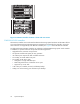
Fibre Channel drive enclosure
Each FC drive enclosure includes the following features:
•3Udrive enclos
ure
• Dual-redundant, active-to-active, 2-Gbps FC loops
• Fourteen 1-inch FC d isks per enclosure
• Environmenta
l Monitoring Unit (EMU)
• Dual 2-Gbps FC I/O modules—A and B loops
• Enhanced fault detection
•SingleGigab
it Interface Converter
• Dual 500-W redundant hot-plug power s upplies and blowers
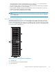
For ease of reference, the disk drives are referred to by their physical location, the drive bay number.
Figure 5 shows the front view of the FC drive enclosure and the physical location of each drive bay.
CXO7942A
1
2
3
4
5
6
7
8
9
10
11
12
13
14
15
Figure 5 F
Cdriveenclosure
1–14 drive bays
15 enclosure status indicators
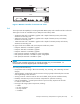
Fibre Channel loop switches
The EVA5000 uses four FC loop switches to connect all of the drive enclosures to the controller pair
via FC cables. Each switch acts as a central point of interconnection and establishes a fault-tolerant
physical loop topology.
The major features of the FC loop switches are:
• 2.125 Gbps operating speed
• Twelve ports
• Half-width, 1U size
• System and p ort status LED indicators
• Universal power supply that operates between 100 to 250 VAC and 50 to 60 Hz
• Small Form-factor Pluggable (SFP) transceivers
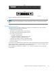
Figure 6 shows the bezel and front view of the FC loop switch.
24
System description