
Instruction Manual


CXO7951
A
12
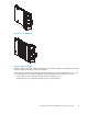
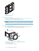
Figure 23 I/O module locations
1. I/O module A
2. I/O module B
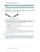
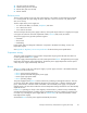
The I/O modules are major components in the Fibre Channel loop. Each module has two ports that
can both transmit and receive data for bidirectional operation. Activating a port requires connecting a
transceiver to the port via fibre optic cables. The por t function d epends upon the loop (see Figure 2 4).
CXO7954
A
3 1
4 2
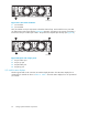
Figure 24 Input and output ports
1. Loop A bottom port
2. Loop A top port
3. Loop B bottom port
4. Loop B top port
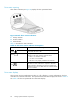
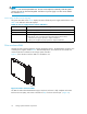
I/O module status displays
The three green LEDs on the A and B I/O mod ules display the status. The LED status displays for an
operational I/O module are shown in Table 1 0. Table 11 shows the status displays for a non operational
I/O module.
62
Storage system hardware components