
Instruction Manual


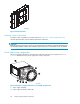

• The I/O module is replaced, if defective.
• The overcurrent condition no longer exists.
NOTE:
A disabled I/O module cannot transfer data and disconnects all the drives in the enclosure from the loop.
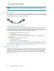
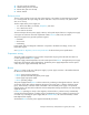
Fiber optic cables
The Enterprise Virtual Array Fibre Channel 9000-Series implementation uses orange, 50-µm, multi-mode,
fibre optic cables. Figure 25 shows the fibre optic cable assembly, which consists of t wo, 2-m fibre optic
strands and small form-factor connectors on each end.
CXO7972
A
Figure 25 2-Gb fibre optic components
To ensure optimum o peration, the fibre optic components (that i s, the transceivers, the fiber optic cable
connectors, and the fiber within the cable) require protection from contamination and mechanical
hazards. Failure to provide this p rotection can reduce the amount of light passing through a component,
thereby degrading operation. Actions that ca n avoid degradation include:
• To avoid breaking the fiber within the cable, do not:
•Kinkthecable.
• Use a cable bend-radius of less than 30 mm (1.18 in).
• To avoid deforming, or possibly breaking the fibre within the cable, do not place heavy objects
on the cable.
• To avoid contaminating the optical connectors:
• Do n ot touch the connectors.
• Never leave the connectors exposed to the air.
• Install a dust cover on each transceiver and fiber cable connector when they are disconnected.
If an open connector is exposed to dust, or there is any doubt about the cleanliness of the connector,
clean the connector as described in Protecting Fiber Optic Connections.
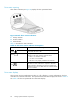
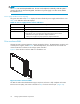
Copper Fibre Channel cables
The Enterprise Virtual Array Fibre Channel 10000-Series implementation uses copper Fibre Channel
cables to connect the drive enclosures to each other, or to the loop switches and to the HSV controllers.
The cables are available in 0.6 -meter and 2.0-meter lengths. Copper cables provide performance
comparable to fiber optic cables. Copper cable connectors differ from fiber o ptic small form-factor
connectors (see Figure 26).
64
Storage system hardware components