
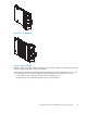
Instruction Manual
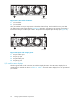


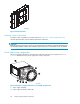
3. AC Input connector with bail
4. Module latch (port-wine colored)
5. Blower tabs (port-wine colored)
6. Blower element
Enclosure pow
er
The two power s
upplies m ou nt in the rear of the enclosure. The supplies are autoranging a nd operate
on a country-s
pecific AC input voltage of 202 to 240 VAC ±10%, 50 to 60 Hz, ±5%, (188 to 264
VAC, 47 to 63 Hz).
The D C outputs of this power supply are:
• +5.1 VDC for t
he EMU, I/O module, backplane, and drives
• +12.1 VDC for the drives
• +12 .5 VDC for the drives
The nominal
output of each power supply is 499 W, with a peak output of 681 W. A single power supply
can support
an enclosure with a full complement of disks, blowers,EMU,andI/Omodule.
The power supply circuitry provides protection against:
• Overloads
• Short circu
its
• Overheating
Power supply status and diagnostic information is reported to the EMU with voltage, current, and
temperature signals.
See Appendix A: Regulatory notices and specifications for the enclosure power specifications.
Temperature sensing
The power supply temperature sensor provides a temperature range signal to the EMU. The E MU can
use this signal to set the blower speed.
The power supply internal temperature can also set the speed of the blower. The higher the power supply
temperature, the faster the speed of the blower. Should the power supply temperature exceed a preset
value, the power supply automatically shuts down.
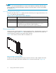
Blowers
The blower mounts on the rear of the power supply. A power supply connector is the interface bet ween
the blow
er and the enclosure for:
•Blowerspeed control to the blower
•Blowerspeed to the EMU through the power supply
• Power s
upply high speed enable
•Bloweroperating voltage
The power-supplymounted blowers cool the enclosure by circulating air through the enclosure. The rate
at which air moves (the air flow) determines the amount of cooling and is a function of blower speed
(rpm). These blowers, under the control of the EMU or the associated power supply, can o perate at
multi
ple speeds. This ensures that when the enclosure temperature changes the blowers can automatically
adjus
ttheairflow.
If a blower is operating too slowly or has stopped (a “blower failure”), internal circuitry automatically
operates the remaining blower at a higher speed. Simultaneously, the error condition is reported to you
in several ways, including the power supply LED, the audible alarm, the enclosure fault LEDs, a nd the
EMU a
lphanumeric display.
Should both blowers fail, the power supplies automatically shut down.
Enterprise Virtual Array 3000/5000 user guide (VCS 3.110)
69