
Instruction Manual
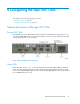
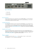
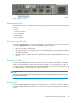
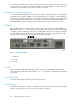
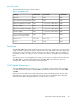
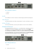
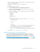

Figure 15 Chassis LEDs
.
1. Heartbeat LED
2. Input Power LED
3. System Fault LED
Power LED (green)
The Power LED indicates the input voltage status at the mpx100/100b logic circuit board. During
normal operation, this LED is illuminated to indicate that the mpx100/100b logic circuit board is
receiving the DC voltage from the power supply.
Heartbeat LED (green)
The Heartbeat LED indicates the status of the internal mpx100/100b processor and any power-on
self test (POST) error results. Following a normal power-up, the Heartbeat LED blinks about once per
second to indicate that the mpx100/100b passed the POST and that the internal mpx100/100b
processor is running. See “Heartbeat LED blink patterns” on page 174 for a description of all Heartbeat
LED blink codes.
System Fault LED (amber)
The System Fault LED illuminates to indicate that a fault exists in the mpx100/100b firmware or
hardware. Fault conditions include POST errors and over-temperature conditions. The Heartbeat LED
shows a blink code for POST errors, IP address conflicts, and the over-temperature condition. See
“Heartbeat LED blink patterns” on page 174 for more information.
Chassis controls
The Maintenance button shown in Figure 16 is the only chassis control; it is used to reset the
mpx100/100b or to recover a disabled mpx100/100b.
Configuring the mpx100/100b52