
Instruction Manual
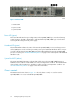
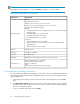

Alert LED (yellow)
The Alert LED indicates any port fault conditions.
Table 13 Port LED messages
Yellow LEDGreen LEDAmber LEDActivity
OFFOFFOFFPower off
ONONONPower on (before F/W Initialization)
OFF3 seconds on—Flash off onceOFFOn-Line link established at 1-Gbps
OFF3 seconds on—Flash off onceONActivity at 1-Gbps
OFF3 seconds on—Flash off twiceOFFOn-Line Link established at 2-Gbps
OFF3 seconds on—Flash off twiceONActivity at 2-Gbps
ONONOFF
Power on (after FW initialization
and/or loss of synchronization)
ONError codeError codeFirmware error
FlashFlashFlashBeacon
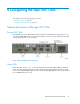
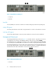
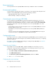
Transceivers
The mpx100/100b supports SFP optical transceivers for the FC ports. A transceiver converts electrical
signals to and from optical laser signals to transmit and receive data. Duplex fiber optic cables plug
into the transceivers, which then connect to the devices. A 1 Gb/s/–2 Gb/s FC port is capable of
transmitting at 1 Gb/s or 2 Gb/s; however, the transceiver must also be capable of delivering these
rates.
The SFP transceivers are hot-pluggable. This means you can remove or install a transceiver while the
mpx100/100b is operating without harming the mpx100/100b or the transceiver. However,
communication with the connected device will be interrupted.
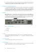
iSCSI/Gigabit Ethernet ports
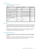
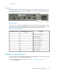
The iSCSI/Gigabit Ethernet ports shown in Figure 18 are RJ-45 connectors that provide connection
to an Ethernet network through a 10/100/1000 Base-T Ethernet cable. The ports are labeled GE1
and GE2.
These ports have two LEDs: the Link Status LED (green) and the Activity LED (green). The Link Status
LED illuminates continuously when an Ethernet connection has been established. The Activity LED
illuminates when data is being transmitted or received over the connection.
EVA iSCSI Connectivity User Guide 55