
Instruction Manual
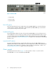
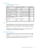

2. Activity LED
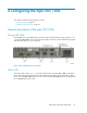
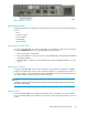
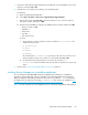
Serial port
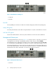
The mpx100/100b is equipped with an RS-232 serial port for maintenance purposes. The serial port
location is shown in Figure 20, and is labeled IOIOI. You can manage the mpx100/100b through
the serial port using the CLI.
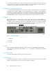
Figure 20 Serial port
.
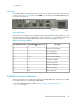
The serial port is connected using a standard 8-wire Ethernet cable and the supplied dongle to convert
the Ethernet RJ–45 connector to a female DB9 connector. Refer to Table 14 for definitions of the serial
port pins for both the mpx100's/100b's RJ–45 connector and the dongle DB9 connector.
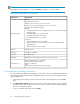
Table 14 Serial port pin definition
Descriptionmpx100/100b RJ–45 pin num-
ber
Dongle DB9 pin number
Data carrier detect (DCD)51
Receive data (RxD)62
Transmit data (TxD)33
Data terminal ready (DTR)2 & 74
Signal ground (GND)45
Data set ready (DSR)56
Request to send (RTS)17
Clear to send (CTS)88
Ring indicator (RI)N/C9
Installation and maintenance
This section describes how to install and configure the mpx100/100b. It also describes how to update
new firmware and recover a disabled mpx100/100b.
For the mpx100/100b hardware installation, see “Installing and upgrading EVA iSCSI
connectivity” on page 41.
EVA iSCSI Connectivity User Guide 57