
Datasheet


Connectors, LEDs, and Switches
Front Panel LEDs
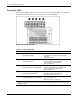
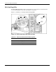
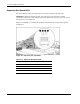
The set of five LEDs on the front of the server indicate system health. Figure 4-4 and Table
4-4 identify and describe the location and function of each of the LEDs.
Figure 4-4: Front panel LEDs
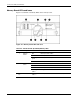
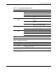
Table 4-4: Front Panel LEDs
LED Description State
1 UID button and LED
Blue = Activated
Blue flashing = System is being managed
remotely
Off = Deactivated
2
Internal health LED*
Green = Normal (system on)
Amber = System health degraded
Red = System has critical failure
Off = System is off
3
External health (power supply) LED
Green = Normal (system on)
Amber = Redundant power supply failure
Red = Critical power supply failure
Off = System is off
4
Embedded NIC activity LED
Green = Network link
Blinking = Network link with activity
Off = No network connection
5
Power On/Standby button and LED
Amber = System is off (auxiliary power present)
Green = System is on
Off = Server has no A/C power
*The internal health LED identifies service events for internal components in a prefailure or failed
condition. For a list of these events, refer to the HP ProLiant ML570 Generation 2 Server Setup and
Installation Guide.
4-6 HP ProLiant ML570 Generation 2 Server Maintenance and Service Guide