
User Manual

Connectors, LEDs, and Switches
System Board LEDs
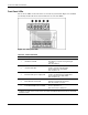
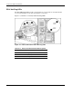
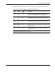
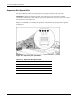
Figure 4-5 and Table 4-5 identify system board LED locations and status indications.
Figure 4-5: System board LEDs
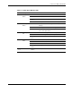
Table 4-5: System Board LEDs
LED Description State
1 PPM 1
2
Processor 1
3
PPM 2
4
Processor 2
Amber = Processor or PPM failed
Off = Normal
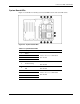
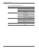
5 Thermal warning
Amber = Thermal event
Off = Normal
6
Memory board interlock
LED
Amber = Memory boards interlock failed
Off = Normal
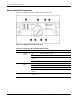
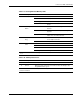
7
Processor 3
8
PPM 3
9
Processor 4
10
PPM 4
Amber = Processor or PPM failed
Off = Normal
HP ProLiant ML570 Generation 2 Server Maintenance and Service Guide 4-7