Service Handbook HP 9000 Series 300 Computers Model 319C+ HP Part Number 98564-90039 FliOW HEWLETT ~~ PACKARD Hewlett-Packard Company 3404 East Harmony Road, Fort Collins, Colorado 80525
NOTICE The Information contained in this document is subject to change without notice. HEWLETT-PACKARD MAKES NO WARRANTY OF ANY KIND WITH REGARD TO THIS MANUAL. INCLUDING. BUT NOT LIMITED TO. THE IMPLIED WARRANTIES OF MERCHANTABILITY AND FITNESS FOR A PARTICULAR PURPOSE. Hewlett-Packard shall not be liable for errors contained herein or direct. indirect. special. incidental or consequential damages in connection with the furnishing. performance. or use of this material.
Printing History New editions of this manual will incorporate all material updated since the previous edition. Update packages may be issued between editions and contain replacement and additional pages to be merged into the manual by the user. Each updated page will be indicated by a revision date at the bottom of the page. A vertical bar in the margin indicates the changes on each page. Note that pages which are rearranged due to changes on a previous page are not considered revised.
Notices Radio Frequency Interference Statements FCC Statement Federal Communications Commission Radio Frequency Interference Statement (U.S.A. Only) The Federal Communications Commission (in Subpart J of Part 15, Docket 20780) has specified that the following notice be brought to the attention of the users of this product.
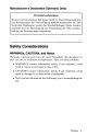
Manufacturer's Declaration (Germany Only) Herstellerbescheinigung Hiermit wird bescheinigt, daB dieses Gerat in Ubereinstimmung mit den Bestimmungen der Postverfiigung 1046/84 funkentstort ist. Der Deutschen Bundespost wurde das Inverkehrbringen dieses Geratcs angezeigt und die Berechtigung zur Uberpriifung der Serie auf Einhaltung der Bestimmungen eingeraumt.
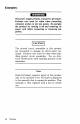
Examples: WARNING The power supply presents a hazard to personnel. Extreme care must be taken when connecting voltmeter probes to the test points. De-energize the product by turning it off and removing its power cord before connecting or removing test probes. I CAUTION I The printed circuit assemblies in this product are susceptible to damage by electro-static discharge. Extreme care must be taken when handling printed circuit assemblies.
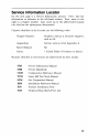
Service Information Locator On the next page is a Service Information Locator. First, find the information to reference in the left-hand column. Next, move to the right to a chapter number. Last, move up to the abbreviated manual title that has the information documented. Chapter identifiers in the Locator use the following codes: Chapter Number: Numbers, such as 2. Inclusive chapters, such as 4-6. Appendices: Letters, such as A for Appendix A.
Service Information Locator Service Information Assembly replacement Block diagrams Booting Operating Systems SIM SHB CRM TTM SPM 1, 2 4 2 Configurations 1 3 1, 5 5 Electrical requirements 1 1 3, A Environmental req uir('ments 1 2 4, A Functional descriptions 3 1, 2, 3 All Monitors People who can help All 4 * * 2, 3 HP -HIL device tests I/O Bus architecture TDS 9 1, 5 Installation PIN 2 Computer tests (;S/80 tests IRM 2 2 All All All 3 All A 1 All 1.
Service Information Locator (cont.) SIM SHB Options/ Accessories 1.3 3 Ordering spare parts 6 8 Part numbprs 6 8 All Periphprals 1 3 All Preventive maintpnancp SPM All 1 All All Product numbers 1 1.3 All A Reference material 7 10 * 4. 5 5 1 11 Site preparation 5 Systems 1 3 Trouhleshooting 5 4 31 4 41 5 Thrn-on TDS All All * All All All All All All All * 1.
x
Table of Contents Chapter 1: Product Information Introduction. . . . . . . . . . . . . . . . . . . . . . . . . . . . . . . . . . . . . . . . . . . .. Features ............................................... , Hewlett-Packard Support ................................. Repair Philosophy ................................... HP Repair Serv ices .................................. , Repair by Customers ................................ , Operating Systems Support .......................... , Serial Numbers . . . . .
Chapter 3: Configuration Bundled Systems ....................................... Supported Configurations. . . . . . . . . . . . . . . . . . . . . . . . . . . . . . .. SPU Configuration Switches. . . . . . . . . . . . . . . . . . . . . . . . . . . . .. HP -HIL Accessories . . . . . . . . . . . . . . . . . . . . . . . . . . . . . . . .. 21 21 22 23 Chapter 4: Troubleshooting Analytic Troubleshooting ................................ Initial Troubleshooting Flowchart. . . . . . . . . . . . . . . . . . . . .
Chapter 9: Diagrams SPU Block Diagram .................................... , Power Supply .......................................... Processor / Add-On RAM Board .......................... , Video-HS HP-IB/SCSI Board ............................ Video Circuit. . . . . . . . . . . . . . . . . . . . . . . . . . . . . . . . . . . . . .. SCSI Circuit ....................................... High-Speed HP-IB Circuit ...........................
xiv
1 Product Information Introduction Information in this handbook refers to the HP 9000 Series 300 tvlodel 319c+ Workstation's SPU. Features Table 1-1. Model 319C+ Workstation Features Product Number Description System Processing Unit MC68020 CPU at 16.67 MHz MC68881 Floating Point Co-CPU, 16.67 MHz MC68851 Memory Management Unit, 16.67 MHz 4, 8, 12, or 16 Mbytes of RAM SPU Interfaces IEEE-488 HP-IB Interface RS-232C Serial Interface IEEE 802.
Table 1-2. Model 319C+ Workstation Options Product Number Options Available Opt. 010 Opt. 011 Opt. 022 Opt. 045 Opt. 060 Opt. 084 Opt. 108 Opt. 112 Opt. 116 Opt. 305 Opt. 306 Opt. 751 2 Product Information Description Add High-Speed HP-IB Interface Add SCSI Interface (Available early 1988) HP-UX on 0.25-inch Tape HP-UX on 3.
Hewlett-Packard Support Support services and policies mentioned in this section are subject to change. Please consult your local Hewlett-Packard Sales and Service Office for the current support policies. Repair Philosophy Field Repair Philosophy for this SPU is assembly, or board level. This means that when a failure occurs, the problem is diagnosed to the assembly having the failed part. That assembly is then replaced. Replacement assemblies are available through local HP Sales and Service Offices.
HP Repair Services There are many hardware support options available, from utilizing customer's maintenance groups to buying full support from the local HP Sales Office. Please contact your local Hewlett-Packard Sales and Service Office for complete information.
Scheduled On-Site Service Provides the lowest on-site support costs for a minimum of twenty-five HP workstation products. HP will make weekly visits to a single central site which the customer specifies. Repair by Customers In addition; customers may obtain service training courses and spare parts to do their own repair. Contact your nearest HP Sales and Service Office for information concerning service training, special tools and test equipment, and spare parts.
Support For An Additional System The following options support an additional syst('m: • Additional System Coverage extends AMS or RCS coverage on the operating system to one additional system under the same system manager. All support is delivered through the central system. • Extended Materials Support extends SMS by providing the right to make one copy of all central system materials for use on one additional system.
Serial Numbers Serial No. XXXX A 01234 ' - - v - ' "'-v-' ~ Location: On the outside of the rear panel. Description: ~._ t 5-digit unique identifying number. Country of Origin Code. Product Code, decoded as: First 2 digits + 60 = Last 2 digits of year product was introduced or significantly changed. Last 2 digits = number of week in year product was introduced or significantly changed.
Technical Data Physical Dimensions Height 104 mm (4.1 inches) Width 325 mm (12.8 inches) Length 444 mm (17.5 inches) Weight 4.55 kg (10 pounds) maximum Vibration Standard Meets Class B requirements Processor Board CPU Type Motorola MC68020 Clock Frequency 16.
LAN Interface Media ThinLAN coax cable (RG 58U) Protocols IEEE 802.
Video-SCSI/HP-IB Board Video Interface High-Resolution Color Shipping Information The shipping container for each SPU includes the Localization Kit, which includes power cords, keyboard cable, HP-HIL cable, Safety and Regulatory Information, and Installation Picture Card. Shipping Weight 9.1 kg (20 pounds) Container Dimensions Width - 533 mm (21 inches) Length - 584 mm (23 inches) Depth - 292 mm (11.5 inches Cube - 0.085 m 3 (3.
HP-HIL Accessories Table 1-3.
Monitors The HP 98551A and 98785A High-Resolution Monochrome Monitor is supported with Model 319C+ Workstations. System Software Table 1-4. HP-UX Operating System Product Number Description HP98515A HP-UX 5.5 AXE (Single-user) HP98595A HP-UX 5.5 AXE (Multi-user) HP98517A HP-UX 5.2 Pgm. Env. (Single-user) HP 98597A HP-UX 5.2 Pgm. Env. (Multi-user) HP 98518A HP-UX 5.2 FORTRAN 77 Compiler (Single-user) HP 98598A HP-UX 5.2 FORTRAN 77 Compiler (Multi-user) HP97055A HP-UX 5.
Standard Tools The following tools are needed to service the SPU: Table 1-6.
SPU/System Tests Table 1-7. Series 200/300 Test Tools Part No. 09800-12300 Description Series 200/300 Test Tools, eight 3.5-inch discs Table 1-8. Series 200/300 Test Tools 3.5-inch Discs Part No. Contents 09800-90001 Series 200/300 Test Tools Manual 09800-10336 Series 200 Computer Tests Disc Rev. 1.1 98561-10334 Series 300 Computer Tests Disc Rev. 2.0 Series 200/300 System Functional Tests Discs: 09800-00334 SFTO Disc Rev. 1.2 09800-11335 SFT1 Disc Rev. 1.2 09800-11336 SFT2 Disc Rev. 1.
Technical Information/ Installation/PM 2 Technical Information Note Technical information listed below should not be interpreted as product specifications. Official product specifications are listed in the HP 9000 Series 300 Hardware Technical Data and Pricing Sheet. Electrical Line voltage/frequency 120 V ac @ 48-66 Hz 240 V ac @ 48-66 Hz Line transient spike immunity (1 nsec rise, 800 nsec duration) 1 KV dc Power Consumption 110 Watts maximum Current Requirements 1. 9 A 1.
Environmental Operating temperature o - 55° Operating humidity 5 - 80% relative Operating altitude 4 572 metres (15 000 feet) C (32 - 104° F) Electromagnetic Interference Standards met FCC Class A VCCI Class 1 VDE Class B, VDE 1046/84 Regulatory Requirements Standards met UL 478, 5th Edition CSA 220-M1986 IEC 380, 2nd Edition; 435, 2nd Edition Physical Dimensions Height 104 mm (4.1 inches) Width 325 mm (12.8 inches) Length 444 mm (17.5 inches) Weight 4.
Shipping Information The shipping container for each SPU includes the Localization Kit, which includes power cords, keyboard cable, HP-HIL cable, Safety and Regulatory Information, and Installation Picture Card. Shipping \Veight 9.1 kg (20 pUUlltb) Container Dimensions Width - 533 mm (21 inches) Length - 584 mm (23 inches) Depth - 292 mm (11.5 inches Cube - 0.085 m 3 (3.21 feet 3 ) HP-HIL and Video Accessories Table 2-1 lists HP-HIL and video accessories compatible with the Model 319C+ Workstations.
Table 2-1.
Preventive Maintenance There is no preventive maintenance requirement for the Model 318M Workstation's SPU.
20 Technical Information/ Installation/PM
Configuration 3 Bundled Systems Refer to the current HP 9000 Series 300 Price List to determine what HP products are bundled into this systems. Supported Configurations Rrfer to the Series 800 Configuration Reference Manual (98561-90020) for the current hardware and software products that are supported.
SPU Configuration Switches Table 3-1.
HP-HIL Accessories HP-HIL devices are limited to a total of 1 A of current and seven addresses per SPU. Table 3-2. HP-HIL Devices and Current/Power Requirements Product Number Device Name mA Watts HP 46021A ITF Keyboard 100 1.2 HP 46060A HP Mouse 200 2.4 HP 46080A Extension Module 25 0.3 HP 46081A 3 Metre Ext. 25 0.3 HP 46082A/B 15/30 Metre Extension l 50 0.6 HP 46083A Rotary Control Knob 110 1.32 HP 46084A ID Module 60 0.72 HP 46085A Control Dials 350 4.
24 Configuration
4 Troubleshooting Analytic Troubleshooting Troubleshooting SPU s is the process of getting answers to these five questions: • What exactly is wrong, or what are the bad symptoms? • Where are the bad symptoms appearing? • When do the bad symptoms occur? • How bad is the problem or to what extent does it occur? • What actually caused the problem in the first place? Getting the answers to these questions usually makes the troubleshooting process much more effective and less costly.
Initial Troubleshooting Flowchart Check Fan & LEOs 26 Goto Dead Goto live Unit Procedure Unit Procedure Troubleshooting
Dead Unit Troubleshooting Flowchart Check Voltage Select Switch and Line Voltage >----I~ Replace: Power >--_~ Goto Live Unit Supply Replace: Processor Board Procedure Troubleshooting 27
Live Unit Troubleshooting Flowchart Replace Indicated Failed Assembly 28 Troubleshooting
Power Supply Technical Information Make sure that the SPU is properly grounded. It requires a three-wire power cahle and the power supply retaining/grounding screw must be installed. Also, make sure that the power supply access door is properly installed. Voltage Tolerance +5 V de 4.89 to 5.25 V de +12 V 11.86 to 12.72 V de -12 V -11.86 to -12.72 V de Voltage Indicators Voltage -12 V de +5 V +12 V de Indication (none) Self-test LED lit at turn-on.
General Failure Indications Table 4-1. Self- Test LED General Failure Indications Failure Indications via Upper Two LEDs LED Pattern General Description of Failure State Indication Only ooss ssss, Where ss ssss Indicates State of Power-up Required Device Missing or DTACK Failure o.dd dddd, where dd dddd Indicates Device Failing Device .odd dddd.
Boot ROM Error Codes Table 4-2. Boot ROM LED Error Codes LEDs Probable Cause Replace or Do 0000 0000 No Failure Detected 0000 0 . 0 . CPU Timer Missing Processor Board 0.00 0.00 Top RAM Failed Check RAM Configuration. 0 ••••••• LEDs failed to acknowledge Processor Board .000 000. CPU Failed Processor Board .000 00 • • Boot ROM Failed Checksum Processor Board • 000 0.00 Top RAM Failed Processor Board . .000 . 0 0 . RAM Failure Add-On RAM Board. Processor Board. • 000 . 0 .
Remote SPU Analysis The SPU and monitor allows remote analysis of problems by means of the beeper. To test the SPU remotely, follow this procedure: 1. Establish a telephone connection with someone at the location of the completely installed workstation. 2. Have them hold the receiver near the speaker output. The speaker is located in most monitors, or in the speaker module. 3. Now have them turn the SPU on. 4. The SPU will go through its self-test and report problems as a series of beeps.
Boot ROM State Codes Table 4-3. LED State Codes In Numerical Order LEDs Test Activity 0000 0000 No failure 0000 000. LED ripple (all on, then off in sequence from MSB) 0000 00.0 Resetting I/O 0000 0 0 . . Checksumming Boot ROM (or LED ripple) 0000 0.00 Testing top RAM (or maybe the Boot ROM checksum failed) 0000 0 • • 0 Searching for boot extension ROMs 0000 Starting test vector list (or LED ripple) 0... 0000 .000 Preloading RAM 0000 . 0 0 . Testing RAM 0000 • • • • LED ripple 000.
34 Thoubleshooting
5 SPU Tests Test Tools Package Contents The combined Series 200/300Test Tools software package is provided on both 3.5-inch discs and O.25-inch tape as shown below: Part N umbe Description 09800-12300 Series 200/300 Test Tools, eight 3.5-inch discs Discs in the 3.5-inch disc package are listed below. Part N umbe Contents 09800-90001 Series 200/300 Test Tools Manual 09800-10336 Series 200 Computer Tests Disc Rev. 1.1 98561-10334 Series 300 Computer Tests Disc Rev. 2.
36 SPU Tests
Adjustments 6 There are no adjustments in the SPU. For adjustments to other products in the workstation, refer to the product's Service Manual or Handbook.
38 Adjustments
Peripherals 7 Supported Peripherals List Due to constant changes of supported peripherals 1 this information is published separately in the Series 300 Configuration Reference Manual (98561-90020). The HP 9000 Series 300 Technical Data Sheet and Hardware Pricing List also has supported peripheral information.
40 Peripherals
8 Parts Lists Parts Information Introduction Field replaceable parts are listed in this chapter for the SPU. Components, such as ICs, are not available for field repair. Parts are available direct from: Corporate Parts Center 333 Logue A venue Mountain View, California 94042 USA Telephone: (415) 968-9200 Parts may be ordered through your local HP Sales and Service Office. To help get parts as soon as possible, please write the address and telephone number of your local HP Office in the spaces below.
Exchange Parts Exchange parts are available for some items at a reduced cost. When an exchange part is ordered, your account will be charged for a new part. Customers have 15 days to return the failed part to receive credit for the difference between a new and exchange part. Please return failed exchange parts to your local HP Sales and Service Office as soon as possible. Place them in anti-static bags (see Parts List for part numbers) and package them securely in a sturdy container.
Printed Circuit Boards Exchange Part No. New Part No. Description 0950-1894 Power supply 98564-69508 98564-66508 Processor board w / 4 Mbyte 98564-69.
HP-HIL Devices Exchange Part No. New Part No. Description 46021-60201 ASCII Keyboard 46020-60001 Keyboard Cable HP 46060A HP Mouse 46081-61601 2.
! 1~ F"19ure 8-1.
SPU Parts List Ref.
SPU Parts List (cont.) Ref.
48 Part~ Lists
9 Diagrams SPU Block Diagram l Power Supply - Processor Board 4/8 Mbyte RAM ~J ~ CPU l~ LAN -1 r""' ~ ~~ RS232 f~ ~y HP-IB ~~ ... ,. HPIL l• ... ,. . .. J " " '" ~ " 4~ ~ ... ,. ..
~ = 115/230 Jumper INPUT tj I ~.
." on (I) fA fA _~~1. -r- BA ' ,Lf'6" r BO \1) 7'---- » c. c. I o:J F~:~ ~____ o ~ XO :D _ 010 Control » 3: OJ o m c. ...
_. < c:< c. (1) 0 (I) 0 =;- 0I c en (") FRAME BUFFER 16 .r I 2-L / RUG -- BARC 0 / STATUS REGISTER DIO BUS INTERFACE ~lOCAl 010 (16 BIT) tr 16 - r--- 16, .r BARC 1 16 / GLAD BUS INTERFACE f--f--- 16, -, - - BARC ROM GLAD BUS (16 81T) 2 G- PLANE 0 PLANE ::;: -a " 4 4Wf= PLANE 3--.-J PLANE 5 PHANTOM PLANE 4L " -OJ I 1~ 21 PLANE ::J: 4/ PLANE ::J: ~ < is fT1 0 4 IRIS ~ c ~ " 0 -I C -I (J) ........... en en - 0 OJ 0 m ... c.
SCSI Circuit ~ I DID Diagrams SCSI Bus 53
- 1 INTERRUPT 1 """- ~ .... BUF -L 100-07 - .. ~ I SOO-S07 J~ REGISTERS S08-S015 I~ .. J I L_ I~ - - ~~ " FIFO FIFO .~ J~ " CO CO Co :t o ~' -~. BUF (') c: - L.. 1- SOOO-S007 " " .t BACKPLANE TO FIFO CONTROL DMA Control ;::;: " I 4~ ..PIJ-~ BUF • " S008-S0015 ,~ """- rABI J~ BUF BUF .. JI • ,r DIO BUS ~ I.. J -BUF ""D .!.. OJ D8-015 L.t - :::r I en }* -L.L BUF to' - NON-DMA CONTROL r ~ J~ """- :t I .. ..
10 Reference Hardware Support Documentation lPart Number Manual Title 09000-90041 HP 9000 Series 200/300/500 Site Preparation Manual 98561-90020 Series 300 Configuration Reference Manual 98562-90005 HP 9000 Series 200/300 Test Tools Manual 98564-90030 HP 9000 Series 300 Model 319C+ Workstation's SPU Service Information Manual 98564-90039 HP 9000 Series 300 Model 319C+ Workstation's SPU Service Handbook 98564-90099 HP 9000 Series 300 Model 319C+Workstation's SPU SelfPaced Hardware Training Guide
56 Reference
Service Notes 11 Service Notes 57
Notes 58 Service Notes
Flin- HEWLETT ~~ PACKARD HP Part Number 98564-90039 Microfiche No. 98564-99039 Requires Binder No. 9282-0683 Printed in U.S.A.