HP KVM Server Console Switch Maintenance and Service Guide May 2006 (Second Edition) Part Number 339820-002
© Copyright 2005, 2006 Hewlett-Packard Development Company, L.P. The information contained herein is subject to change without notice. The only warranties for HP products and services are set forth in the express warranty statements accompanying such products and services. Nothing herein should be construed as constituting an additional warranty. HP shall not be liable for technical or editorial errors or omissions contained herein. Microsoft, Windows, and Windows NT are U.S.
Contents Customer self repair ...................................................................................................................... 6 Parts only warranty service ......................................................................................................................... 6 Illustrated parts catalog ............................................................................................................... 16 Exploded view .....................................................
When When When When When When When When When When When the the the the the the the the the the the local user cannot view the OSD copyright notice ................................................................ 47 local user cannot view the OSD flag ................................................................................. 48 OSD is distorted or not readable ...................................................................................... 48 OSD is inaccessible ...............................
Compatible console switch models ............................................................................................................ 62 Compaq Server Console Switch ...................................................................................................... 62 HP IP Console Switch ..................................................................................................................... 63 Cascading an HP KVM Server Console Switch with another HP KVM Server Console Switch ......
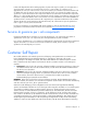
Customer self repair HP products are designed with many Customer Self Repair (CSR) parts to minimize repair time and allow for greater flexibility in performing defective parts replacement. If during the diagnosis period HP (or HP service providers or service partners) identifies that the repair can be accomplished by the use of a CSR part, HP will ship that part directly to you for replacement. There are two categories of CSR parts: • Mandatory—Parts for which customer self repair is mandatory.
• Obligatoire - Pièces pour lesquelles la réparation par le client est obligatoire. Si vous demandez à HP de remplacer ces pièces, les coûts de déplacement et main d'œuvre du service vous seront facturés. • Facultatif - Pièces pour lesquelles la réparation par le client est facultative. Ces pièces sont également conçues pour permettre au client d'effectuer lui-même la réparation.
In base alla disponibilità e alla località geografica, le parti CSR vengono spedite con consegna entro il giorno lavorativo seguente. La consegna nel giorno stesso o entro quattro ore è offerta con un supplemento di costo solo in alcune zone. In caso di necessità si può richiedere l'assistenza telefonica di un addetto del centro di supporto tecnico HP. Nel materiale fornito con una parte di ricambio CSR, HP specifica se il cliente deve restituire dei componenti.
stellen. Im Falle von Customer Self Repair kommt HP für alle Kosten für die Lieferung und Rücksendung auf und bestimmt den Kurier-/Frachtdienst. Weitere Informationen über das HP Customer Self Repair Programm erhalten Sie von Ihrem Servicepartner vor Ort. Informationen über das CSR-Programm in Nordamerika finden Sie auf der HP Website unter (http://www.hp.com/go/selfrepair).
Para obtener más información acerca del programa de Reparaciones del propio cliente de HP, póngase en contacto con su proveedor de servicios local. Si está interesado en el programa para Norteamérica, visite la página web de HP siguiente (http://www.hp.com/go/selfrepair). Servicio de garantía exclusivo de componentes La garantía limitada de HP puede que incluya un servicio de garantía exclusivo de componentes.
Garantieservice "Parts Only" Het is mogelijk dat de HP garantie alleen de garantieservice "Parts Only" omvat. Volgens de bepalingen van de Parts Only garantieservice zal HP kosteloos vervangende onderdelen ter beschikking stellen. Voor de Parts Only garantieservice is vervanging door CSR-onderdelen verplicht. Als u HP verzoekt deze onderdelen voor u te vervangen, worden u voor deze service reiskosten en arbeidsloon in rekening gebracht.
Customer self repair 12
Customer self repair 13
Customer self repair 14
Customer self repair 15
Illustrated parts catalog In this section Exploded view ....................................................................................................................................... 16 System components ................................................................................................................................
Item Description Original spare part number Modified spare part number Customer self repair (on page 6) 3 SPS—BRKT, EXPSN MOD, KVM/IP 306808-001 — No3 4 SPS—ADPTR, INTFC, KYBD/VID/MSE, PS/2 286597-001‡ See requirement 396632-001 No3 5 SPS—ADPTR, INTFC, KYBD/VID/MSE, USB 340388-001‡ See requirement 396633-001 No3 6 SPS—CBL, KYBD/VID/MSE, CT5, 3FT 286592-001 — No3 SPS—CBL, KYBD/VID/MSE, CT5, 6FT 286593-001 SPS—CBL, KYBD/VID/MSE, CT5, 12FT 286594-001 SPS—CBL, KYBD/VID/MSE, CT5, 20FT
2 Optional: Opzionali—Parti la cui riparazione da parte del cliente è facoltativa. Si tratta comunque di componenti progettati per questo scopo. Se tuttavia il cliente ne richiede la sostituzione ad HP, potrebbe dover sostenere spese addizionali a seconda del tipo di garanzia previsto per il prodotto. 3 No: Non CSR—Alcuni componenti HP non sono progettati per la riparazione da parte del cliente.
System components Item Description 1 KVM Server Console Switch 2 Expansion Module Illustrated parts catalog 19
Item Description 3 PS/2 Interface Adapter 4 USB Interface Adapter 5 UTP CAT5 cable Illustrated parts catalog 20
Replaceable spare parts In this section HP KVM Server Console Switch spares kit ................................................................................................. 21 Console switch hardware spares kit.......................................................................................................... 22 Interface adapter spares kits .................................................................................................................... 23 Expansion module spares kit..........
Console switch hardware spares kit 341519-001 SPS—HDWE, MNT KIT, CNSL, KVM SWT Replaceable spare parts 22
Interface adapter spares kits Description Original spare part number Modified spare part number SPS—ADPTR, INTFC, KVM, USB 340388-001‡ See requirement 396633-001 SPS—ADPTR, INTFC, KYBD/VID/MSE, PS/2 286597-001‡ See requirement 396632-001 SPS—ADAPTER, SERIAL INTERFACE* 375203-001‡ See requirement 396634-001 * not shown ‡REQUIREMENT: For Customers in the EU only. The use of the Original Spare part is regulated by RoHS legislation§.
Expansion module spares kit Description Original spare part number Modified spare part number SPS—BD-EXPN MOD, KYBD/VID/MSE 286600-001‡ See requirement 396635-001 ‡REQUIREMENT: For Customers in the EU only. The use of the Original Spare part is regulated by RoHS legislation§. If your unit contains a part that is labelled with the Modified Spare number, the Modified Spare must be ordered as the replacement part in the EU.
Expansion module hardware spares kit 306808-001 SPS—BRKT, EXPSN MOD, KVM/IP UTP CAT5 cable spares kit Description Spare part number SPS—CBL, KYBD/VID/MSE, CT5, 3FT 286592-001 SPS—CBL, KYBD/VID/MSE, CT5, 6FT 286593-001 SPS—CBL, KYBD/VID/MSE, CT5, 12FT 286594-001 SPS—CBL, KYBD/VID/MSE, CT5, 20FT 286595-001 SPS—CBL, KYBD/VID/MSE, CT5, 40FT 286596-001 Replaceable spare parts 25
Serial cable spares kit 154020-001 SPS—CA & HDWE KIT, MISC Replaceable spare parts 26
Removal and replacement procedures In this section Safety considerations.............................................................................................................................. 27 Required tools........................................................................................................................................ 27 Removal and replacement procedure tips ..................................................................................................
Removal and replacement procedure tips After completing all necessary removal and replacement procedures, power on any attached devices to be sure that all components are operating properly. IMPORTANT: As you are removing the console switch components, be sure to retain the screws in a safe place and separate them according to their type. Removing the console switch 1. Power down the console switch and any attached devices. 2. Disconnect all cabling.
Item Description 1 Server 2 Expansion module 3 Console switch 4 USB Interface Adapter 5 PS/2 Interface Adapter Removing the console switch side-mount hardware 1. Remove the screws securing the console switch to the rail. 2. Remove the cage nuts, if necessary. 3. Lift the side-mounting brackets up and away from the rack.
4. Remove the screws securing the side-mounting brackets to the console switch. Removing the console switch standard-mount hardware 1. Remove the screws securing the console switch to the rail.
2. Slide the console switch out of the rack. 3. Remove the cage nuts, if necessary. 4. Remove the screws securing the 1U brackets to the console switch.
Removing the console switch cantilever-mount hardware 1. Remove the screws securing the console switch to the rail. 2. Remove the clip nuts or cage nuts, if necessary. 3. Remove the screws securing the 1U brackets to the console switch. Replacing the console switch side-mount hardware Type A—square- and round-hole rails 1. Remove the four screws, two on each side, from the console switch.
2. Attach the side-mounting brackets to the console switch using the four screws you removed. 3. Slide the side-mounting bracket tabs into the U locations on each side of the rack.
4. Secure the console switch to the rails using four self-tapping screws, two on each side. Type B—square-hole rails 1. Remove the four screws, two on each side, from the console switch. 2. Attach the side-mounting brackets to the console switch using the four screws you removed.
3. Slide the side-mounting bracket tabs into the U locations on each side of the rack. 4. Install four cage nuts into the side-mounting bracket U locations. 5. Secure the console switch to the rails, using four M-6 screws, two on each side. Replacing the console switch standard-mount hardware 1. Remove the four screws, two on each side, from the console switch.
2. Attach the 1U brackets to the console switch using the four screws you removed. 3. Install a cage nut behind each rear rail if they have not already been installed. 4. Slide the console switch into the rear of the 1U product.
5. Secure the console switch to the rails using two M-6 screws, one on each side. Replacing the console switch cantilever-mount hardware Type A—round-hole rails 1. Remove the four screws, two on each side, from the console switch. 2. Attach the 1U brackets to the console switch using the four screws you removed.
3. Install up to six clip nuts. 4. Secure the console switch to the rails, using the appropriate number of T-25 Torx screws. Type B—square-hole rails 1. Remove the four screws, two on each side, from the console switch.
2. Attach the 1U brackets to the console switch using the four screws you removed. 3. Install up to six cage nuts.
4. Secure the console switch to the rails using the appropriate number of M-6 screws. Removing the expansion module 1. Disconnect all cabling. NOTE: Identification labels are provided on the UTP CAT5 cables to mark the ports to which they are connected. 2. Remove the expansion module from the rack. If the expansion module was Velcro-mounted, pull the expansion module away from the rack.
If the expansion module was side-mounted to the rack, remove the bottom screw and lift the expansion module away from the rack.
If the expansion module was rail-mounted, remove the two screws and cage nuts securing the expansion module to the internal rack rail. Replacing the expansion module 1. Mount the expansion module into the rack. 2. Reconnect the cabling according to the identification labels provided on the UTP CAT5 cables. -orLocate up to nine UTP CAT5 cables. a. Connect a UTP CAT5 cable to the server connection port ("Components" on page 71) on the console switch. b.
Removing and replacing the expansion module hardware Remove the screws securing the hardware to the expansion module. To replace the component, reverse the removal procedure. Removing the interface adapter IMPORTANT: The cables on the PS/2 Interface Adapter have a locking mechanism to provide a secure cable connection. To properly disconnect the keyboard and mouse cables, grasp and slide the housing back to release the locking mechanism, and then remove the cable. 1.
Troubleshooting In this section Troubleshooting sequence ....................................................................................................................... 44 Diagnosing the problem.......................................................................................................................... 46 Troubleshooting sequence If you cannot solve the customer's problem using this troubleshooting sequence or any of the following tools, escalate to the next level of support.
Has the customer performed the Run Diagnostics feature? 1. Ask the customer to perform Run Diagnostics ("Running System Diagnostics" on page 56). NOTE: In a cascaded configuration, the Run Diagnostics feature does not perform diagnostics on cascaded console switches. The Run Diagnostics feature must be performed locally on each console switch. To locally connect your cascaded console switch, refer to "How do I locally connect a cascaded console switch? (on page 52)." 2.
Diagnosing the problem This section covers the steps to quickly isolate a problem. When the activity light indicator is not on 1. Ask the customer to be sure that the console switch is powered on and that the power source is valid. 2. Ask the customer to be sure that the cable connections are correct ("Are the cable connections correct?" on page 45).
5. Ask the customer if the UTP CAT5 cables being used are the correct cable length ("Connection length table" on page 74). 6. Ask the customer if the standard UTP CAT5 cables supplied by HP are being used. The cables being used must be unshielded twisted pair, utilizing all four pairs of wires. 7. Ask the customer if an expansion module is being used, and if so to be sure that the console switch is connected to the IN port on the expansion module.
When the local user cannot view the OSD flag Ask the customer to preview the preferences selected in the OSD to determine if the local port display has been disabled or set to time out. If the preferences are set not to display the OSD flag or to have the flag time out, then the OSD flag does not display. When the OSD is distorted or not readable Ask the customer to be sure that the monitor to which the target server is set to supports the refresh rate.
When the video resolution is distorted Ask the customer to refer to the connection length table (on page 74).
Frequently asked questions In this section Are the expansion module ports hot-pluggable?......................................................................................... 50 Are the interface adapters hot-pluggable? ................................................................................................. 50 Are the keyboard, monitor, and mouse connections on the console switch hot-pluggable? .............................. 50 Are the server connections on the console switch hot-pluggable? ....
Are the server connections on the console switch hotpluggable? Yes. Can the console switch be mounted in a round-hole rack? Yes, the console switch can be mounted in a round-hole rack using the standard-mount installation ("Replacing the console switch standard-mount hardware" on page 35). Can the console switch be side-mounted in a round-hole rack? No. Do you have to power down a server to replace an interface adapter? No. Does the console switch support HP legacy console switches? No.
NOTE: You can also press the Ctrl key twice within one second to launch the OSD. You can use this key sequence in any place you see Print Scrn. How do I cascade console switches? Refer to "Cascading console switches (on page 62)." How do I change the keyboard language? Language-specific keyboard emulation in the interface adapter ("Replacing the interface adapter" on page 43) is determined by the language chosen on the OSD.
How do I look at my interface adapter firmware version? Refer to "Displaying the interface adapter firmware version (on page 57)." How do I turn the screen saver off? 1. From the Security dialog box, deselect Enable Screen Saver. 2. Click OK to save settings. To immediately activate the screen saver, press the Print Scrn key, and then press the Pause key. This command only works when the user is connected to a server.
Why can remote HP IP Console Switch users not access servers attached to a cascaded HP KVM Server Console Switch? In order for remote HP IP Console Switch users to access servers attached to a cascaded HP KVM Server Console Switch, the HP KVM Server Console Switch must be in Free Mode or have the screen saver enabled. To enable Free Mode on the HP KVM Server Console Switch, press the Print Scrn key, the Alt + 0 keys, or click Disconnect in the Main dialog box.
Diagnostic tools In this section Activating Run Diagnostics ...................................................................................................................... 55 Running System Diagnostics..................................................................................................................... 56 Activating Run Diagnostics 1. From the Main dialog box, click Commands>Run Diagnostics. A warning message is displayed indicating that all users will be disconnected. 2.
A passed test is indicated with a green circle, and a failed test is indicated by a red X. The test is complete when the last test symbol displays. 4. (Optional) If you have any offline interface adapters, you can click Clear to remove them from the list. 5. (Optional) If you have any suspect interface adapters, you can click Display. The Suspect interface adapter dialog box is displayed.
Displaying the firmware version In this section Displaying the console switch firmware version.......................................................................................... 57 Displaying the interface adapter firmware version...................................................................................... 57 Displaying the console switch firmware version NOTE: Provide the application version number when communicating with HP customer service centers. 1. Connect to the local port. 2.
4. Click IA to access the IA Selection dialog box to view individual interface adapter cable version information. The IA Selection dialog box is displayed. 5. To view the selected interface adapter cable, click Version. The IA Version dialog box is displayed. 6. Click X to exit.
Updating the firmware In this section Updating the console switch firmware....................................................................................................... 59 Updating the cascaded console switch firmware ........................................................................................ 59 Updating the interface adapter firmware...................................................................................................
The update process has three updates—Loading Application Firmware, Loading Graphics Chip, and Loading System Data. You see a progress bar for each of those three updates. The firmware update is not done until all of the updates have been loaded. When the firmware is updated, the following message indicating "Update Complete" is displayed. e. Click Done. 3. Update the attached interface adapter firmware ("Updating the interface adapter firmware" on page 60). 4. Power off the cascaded console switch. 5.
2. Click IA. The IA Selection dialog box is displayed. 3. Select the individual interface adapter, and click Version. The IA Version dialog box is displayed. 4. Click Load Firmware.
Cascading console switches In this section Compatible console switch models ........................................................................................................... 62 Cascading an HP KVM Server Console Switch with another HP KVM Server Console Switch .......................... 63 Cascading a Compaq Server Console Switch with an HP KVM Server Console Switch................................... 65 Cascading an HP KVM Server Console Switch with an HP IP Console Switch.........................
HP IP Console Switch CAUTION: Do not use interface adapters to cascade HP IP Console Switches with console switches. If interface adapters are used to cascade these products, undesirable operations might occur. CAUTION: While cascading console switches, be sure that the console switch is cascaded below the HP IP Console Switch. Undesirable operations might occur if these specific cascading sequences are not followed. The following HP IP Console Switches can be integrated into the console switch system.
22. Update all interface adapter firmware ("Updating the interface adapter firmware" on page 60). The following figure shows an HP KVM Server Console Switch cascaded to another HP KVM Server Console Switch. The top console switch is the main console switch, while the bottom console switch is the cascaded console switch. CAUTION: Do not use interface adapters to cascade console switches with console switches. If interface adapters are used to cascade these products, undesirable operations might occur.
Item Description 6 KVM cable 7 Local port 8 Cascaded console switch * not shown Cascading a Compaq Server Console Switch with an HP KVM Server Console Switch 1. Mount the console switches in the rack. 2. Connect the local port KVM cable to the console switch. 3. Connect a UTP CAT5 cable to the server connection port ("Components" on page 71) on the console switch. 4. Connect the other end of that same UTP CAT5 cable to the RJ-45 port on the interface adapter. 5.
Example of a Compaq Server Console Switch cascade configuration Item Description 1 Server 2 KVM cable 3 PS/2 Interface Adapter 4 UTP CAT5 cable 5 Main Compaq Server Console Switch 6 Local port 7 Cascaded console switch Cascading an HP KVM Server Console Switch with an HP IP Console Switch NOTE: To perform a firmware upgrade for a cascaded HP KVM Server Console Switch and all attached interface adapters, you must locally connect the keyboard, monitor, and mouse to the cascaded HP KVM Server
2. Locate a UTP CAT5 cable and connect one end to the server connection port ("Components" on page 71) on the cascaded HP KVM Server Console Switch. 3. Connect the other end of that same UTP CAT5 cable to the RJ-45 port on the interface adapter. 4. Connect the interface adapter to the appropriate ports on the server. 5. Repeat steps 1 through 3 for any other servers to be added to this system. 6. Connect the local port KVM cable to the cascaded HP KVM Server Console Switch. 7.
Example of an HP IP Console Switch cascade configuration Item Description 1 Server 2 PS/2 Interface Adapter or USB Interface Adapter* 3 UTP CAT5 cable 4 UTP CAT5 cable 5 KVM cable 6 Main HP IP Console Switch 7 Local port 8 Cascaded HP KVM Server Console Switch * not shown Cascading console switches 68
Viewing and selecting ports and servers In this section Viewing servers...................................................................................................................................... 69 Viewing the Port column.......................................................................................................................... 69 Viewing the Server Status column .............................................................................................................
Port number of the first console switch Port number of the cascaded console switch Server Status Icon displayed ("Viewing the Server Status column" on page 70) Description 02 The servers are connected to an expansion module so they are using the same port. You can tell that the expansion modules are not cascaded because they do not have the second port numbers. 02 The servers are connected to an expansion module so they are using the same port.
Component identification In this section Components .......................................................................................................................................... 71 EID Location for the interface adapter ....................................................................................................... 71 Serial number location ............................................................................................................................
recognize and manage attached peripherals, such as the interface adapter, and assigns paths for data transmission. The EID is located on the back of the interface adapter. Serial number location You must provide the serial number to HP when requesting information or ordering spare parts. The serial number for the console switch is located on the bottom of the unit.
Specifications In this section Console switch spares specifications ........................................................................................................ 73 Connection length table .......................................................................................................................... 74 Console switch spares specifications Spare kit description Unit weight Dimensions 340386-001 (without rails) (packaged size) SPS—SWITCHBOX, 1U, RCKMNT, 1 x 8 2.04 kg (4.
Connection length table The console switch offers optimum video performance when the distance between the server and console switch is 15.24 m (50 ft) or less (1280 x 1024 at 75 Hz). The system is capable of operation at distances up to 30.48 m (100 ft) at reduced video resolutions (800 x 640 at 60 Hz, worst case). 15.24 m (50 ft) 1280 x 1024 1024 x 768 800 x 640 X X X 22.86 m (75 ft) — — X 30.
Technical support In this section Before you contact HP............................................................................................................................. 75 HP contact information............................................................................................................................
Acronyms and abbreviations CRC cyclic redundant checks EID electronic identification number EPR engineer problem resolution IA interface adapter KVM keyboard, video, and mouse OSD on-screen display RAM random access memory RMA return material authorization USB universal serial bus UTP unshielded twisted pair VDC voltage direct-current VGA video graphics array Acronyms and abbreviations 76
Index 2 286597-001 SPS-ADPTR, INTFC, KYBD/VID/MSE 23 3 340386-001 SPS-SWITCH, SVR CNSL, KVM, 0 x 1 x 8 21 340387-001 SPS-SWITCH, SVR CNSL, KVM, 0 x 2 x 16 21 340388-001 SPS-ADPTR, INTFC, KVM, USB, 1PK 23 341519-001 SPS-HDWE, MNT KIT, CNSL, KVM SWT 22 375203-001 SPS-ADAPTER, SERIAL INTERFACE 23 396630-001 21 396631-001 21 396633-001 23 A accessing servers 54 activating Run Diagnostics 45, 48, 53, 55 activity indicator light not on 44, 46 configuration of system 64, 66, 68 configuration options 28, 63, 65,
languages, keyboard 52 local user, cannot view OSD 47, 48 SPS-BD-EXPN MOD, KYBD/VID/MSE 24 supported models 51 system, does not recognize cascaded console switches 48 M T Main dialog box 70 management tools 55 monitor 50 mouse 50 tips, removal and replacement procedures 28 tools 27, 55 troubleshooting 44 troubleshooting sequence 44 O U OSD, cannot view 47, 48, 49 OSD, launching 51 updating the firmware 44, 46, 48, 59, 60 upgrading interface adapter firmware 48, 60 UTP CAT5 cable spares kit 25, 53