HP EliteBook x360 1030 G2 Maintenance and Service Guide IMPORTANT! This document is intended for HP authorized service providers only.
© Copyright 2017 Hewlett-Packard Development Company, L.P. Bluetooth is a trademark owned by its proprietor and used by HP Inc. under license. Intel, Celeron, and Pentium are U.S. registered trademarks of Intel Corporation. Microsoft and Windows are either registered trademarks or trademarks of Microsoft Corporation in the United States and/or other countries. SD Logo is a trademark of its proprietor. The information contained herein is subject to change without notice.
Safety warning notice WARNING! To reduce the possibility of heat-related injuries or of overheating the device, do not place the device directly on your lap or obstruct the device air vents. Use the device only on a hard, flat surface. Do not allow another hard surface, such as an adjoining optional printer, or a soft surface, such as pillows or rugs or clothing, to block airflow. Also, do not allow the AC adapter to contact the skin or a soft surface, such as pillows or rugs or clothing, during operation.
iv Safety warning notice
Table of contents 1 Product description ....................................................................................................................................... 1 2 External component identification .................................................................................................................. 4 Locating hardware .................................................................................................................................................
Thermal sensor board ....................................................................................................................... 33 Fan ..................................................................................................................................................... 34 Speakers ............................................................................................................................................ 35 TouchPad cable ...........................................
Using the HP Recovery partition (select products only) ................................................. 64 Using HP Recovery media to recover .............................................................................. 64 Changing the computer boot order ................................................................................ 65 Removing the HP Recovery partition (select products only) ......................................... 66 10 Statement of memory volatility .................................
viii
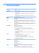
1 Product description Category Description Product Name HP EliteBook x360 1030 G2 Processors ● Intel® Core™ i7-7600U 2.80-GHz (SC turbo up to 3.90-GHz) processor (4.0-MB SmartCache, dual core, 7.5-W) ● Intel Core i5-7300U 2.60-GHz (SC turbo up to 3.50-GHz) processor (3.0-MB SmartCache, dual core, 7.5-W) ● Intel Core i5-7200U 2.50-GHz (SC turbo up to 3.10-GHz) processor (3.0-MB SmartCache, dual core, 7.
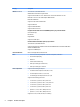
Category Description Wireless (continued) Two built-in M.2 / PCIe WLAN antennas WLAN module is soldered to the system board Support for the Intel 802.11 2×2ac + Bluetooth 4.2 1216 vPro and Intel 802.11 2×2ac + Bluetooth 4.
Category Description Security ● Support for Trusted Platfom Module (TPM) 1.2/2.
2 External component identification Locating hardware To find out what hardware is installed on your computer: ▲ Type device manager in the taskbar search box, and then select the Device Manager app. A list displays all the devices installed on your computer. For information about system hardware components and the system BIOS version number, press fn+esc (select products only).
Display Item Component Description (1) WWAN antennas (2)* (select products only) Send and receive wireless signals to communicate with WWANs. (2) Internal microphones (2) Record sound. (3) Infrared camera lights (2) On: The infrared camera is in use. (4) Webcam Records video and captures photographs. Some models allow you to video conference and chat online using streaming video. To use the webcam: ▲ Type camera in the taskbar box, and then select Camera.
Item Component Description Click the question mark icon in the taskbar. 2. Select My PC, select the Specifications tab, and then select User Guides. Fingerprint reader 6 Component Description Fingerprint reader (select models only) Allows a fingerprint logon to Windows, instead of a password logon.
Lights Component Description (1) Caps lock light On: Caps lock is on, which switches the key input to all capital letters. (2) fn lock light On: The fn key is locked. (3) Privacy key light On: Privacy zone is on, which helps prevent side-angle viewing. (4) Mute light ● On: Computer sound is off. ● Off: Computer sound is on. ● On: Microphone sound is off. ● Off: Microphone sound is on. (5) Microphone mute light (6) num lk light On: Num lock is on.
Special keys Component Description (1) esc key Displays system information when pressed in combination with the fn key. (2) fn key Executes frequently used system functions when pressed in combination with the esc key, or other key. These key combinations are called hot keys. (3) Windows key Opens the Start menu. NOTE: Pressing the Windows key again will close the Start menu. (4) Actions keys Execute frequently used system functions.
TouchPad Item Component Description (1) TouchPad zone Reads finger gestures to move the pointer to activate items on the screen. (2) Left TouchPad button Functions like the left button on an external mouse. (3) Right TouchPad button Functions like the right button on an external mouse.
Left side Component (1) Description Power button ● When the computer is off, press the button to turn on the computer. ● When the computer is on, press the button briefly to initiate Sleep. ● When the computer is in the Sleep state, press the button briefly to exit Sleep. ● When the computer is in Hibernation, press the button briefly to exit Hibernation. CAUTION: Pressing and holding down the power button results in the loss of unsaved information.
Component (4) Description Audio-out (headphone)/Audio-in (microphone) jack (continued) 1. Type support in the taskbar search box, and then select the HP Support Assistant app. – or – Click the question mark icon in the taskbar. 2. Select My PC, select the Specifications tab, and then select User Guides. NOTE: When a device is connected to the jack, the computer speakers are disabled. (5) Volume button Controls speaker volume on the computer.
Right side Component (1) Description microSD memory card reader Reads optional memory cards that store, manage, share or access information. To insert a card: 1. Hold the card label-side up, with the connectors facing the computer. 2. Inser the card into the memory card reader, and then press in on the card until it is firmly seated. To remove a card; ▲ (2) USB Type-C Thunderbolt port Press in on the card, and then remove it from the memory card reader.
Component Description (6) Battery light (continued) ● Off: The battery is not charging. (7) Power connector Connects an AC adapter. Bottom Item Component Description (1) Speakers (2) Produce sound. (2) Vents (3) Enable airflow to cool internal components. NOTE: The computer fan starts up automatically to cool internal components and prevent overheating. It is normal for the internal fan to cycle on and off during routine operation.
3 Illustrated parts catalog NOTE: HP continually improves and changes product parts. For complete and current information on supported parts for the computer, go to http://partsurfer.hp.com, select the country or region, and then follow the on-screen instructions. Service label When ordering parts or requesting information, provide the computer serial number and model number provided on the service tag.
Component (1) HP product name (select products only) (2) Serial number (3) Product number (4) Warranty period (5) Model name (select products only) ● Regulatory label(s)—Provide(s) regulatory information about the computer. ● Wireless certification label(s)—Provide(s) information about optional wireless devices and the approval markings for the countries or regions in which the devices have been approved for use.
Computer major components 16 Chapter 3 Illustrated parts catalog
Item Component (1) Display assembly: The TouchScreen display is spared only as an entire assembly. (2) Spare part number 13.3-in, UHD, BrightView (3840×2160), UWVA TouchScreen display panel assembly 917928-001 13.
Item (3) Component Spare part number For use in Turkey 920484-141 For use in the United Kingdom 920484-031 For use in the United States 920484-001 TouchPad (includes NFC board cable) 924936-001 NOTE: The TouchPad spare part kit does not include the TouchPad bracket or TouchPad cable. The TouchPad cable is included in the Cable Kit, spare part number 917893-001, which also includes the NFC board cable. The TouchPad bracket is not spared as a separate component.
Item (8) Component Spare part number HP hs3210 WW HSPA+ without GPS WWAN module 860726-001 Solid-state drive: 512-GB Turbo Drive G2 solid-state drive with TLC 917926-001 256-GB Turbo Drive G2 solid-state drive with TLC 917925-001 256-GB M.2 SATA SED solid-state drive with Opal2 and TLC 917924-001 128-GB M.
Component Spare part number For use in Denmark 213353-001 For use in Europe 213350-001 For use in India 404827-001 For use in Israel 398063-001 For use in Italy 213352-001 For use in Japan 226768-001 For use in North America 213349-001 For use in the People’s Republic of China 286497-001 For use in South Korea 267836-001 For use in Switzerland 213354-001 For use in Taiwan 393313-001 For use in the United Kingdom and Singapore 213351-001 Power cord – C5 connector, 3-pin, black, 1.
Component Spare part number For use in Thailand 285096-012 and 285096-006 For use in the United Kingdom and Singapore 213351-013 and 213351-008 Power cord – C5 connector, 3-pin, black, 0.50-m, for use only in Europe 213350-011 Power cord – Option-917, 3-cord, 1.83-m, RoHS 361240-00 Power cord – Option-917, 3-cord, 1.
4 Removal and replacement preliminary requirements Tools required You will need the following tools to complete the removal and replacement procedures: ● Flat-bladed screw driver ● Magnetic screw driver ● Phillips P0 screw driver ● T4 Torx screw driver Service considerations The following sections include some of the considerations that you must keep in mind during disassembly and assembly procedures.
Cables and connectors CAUTION: When servicing the computer, be sure that cables are placed in their proper locations during the reassembly process. Improper cable placement can damage the computer. Cables must be handled with extreme care to avoid damage. Apply only the tension required to unseat or seat the cables during removal and insertion. Handle cables by the connector whenever possible. In all cases, avoid bending, twisting, or tearing cables.
Grounding guidelines Electrostatic discharge damage Electronic components are sensitive to electrostatic discharge (ESD). Circuitry design and structure determine the degree of sensitivity. Networks built into many integrated circuits provide some protection, but in many cases, ESD contains enough power to alter device parameters or melt silicon junctions. A discharge of static electricity from a finger or other conductor can destroy static-sensitive devices or microcircuitry.
Packaging and transporting guidelines Follow these grounding guidelines when packaging and transporting equipment: ● To avoid hand contact, transport products in static-safe tubes, bags, or boxes. ● Protect ESD-sensitive parts and assemblies with conductive or approved containers or packaging. ● Keep ESD-sensitive parts in their containers until the parts arrive at static-free workstations. ● Place items on a grounded surface before removing items from their containers.
Equipment guidelines Grounding equipment must include either a wrist strap or a foot strap at a grounded workstation. ● When seated, wear a wrist strap connected to a grounded system. Wrist straps are flexible straps with a minimum of one megohm ±10% resistance in the ground cords. To provide proper ground, wear a strap snugly against the skin at all times. On grounded mats with banana-plug connectors, use alligator clips to connect a wrist strap.
5 Removal and replacement procedures CAUTION: Components described in this chapter should only be accessed by an authorized service provider. Accessing these parts can damage the computer or void the warranty. NOTE: HP continually improves and changes product parts. For complete and current information on supported parts for your computer, go to http://partsurfer.hp.com, select your country or region, and then follow the on-screen instructions.
2. Use a case utility tool (1) or similar thin plastic tool to separate the rear edge (2) of the bottom cover and the keyboard/top cover. 3. Remove the bottom cover (3) by sliding it up and back at an angle. Reverse this procedure to install the bottom cover.
Battery Description Spare part number 3-cell, 57-WHr, 4.94-AHr, Li-ion battery (includes cable) 863280-855 Before removing the battery, follow these steps: 1. Turn off the computer. If you are unsure whether the computer is off or in Hibernation, turn the computer on, and then shut it down through the operating system. 2. Disconnect the power from the computer by unplugging the power cord from the computer. 3. Disconnect all external devices from the computer. 4.
Solid-state drive Description Spare part number 512-GB Turbo Drive G2 solid-state drive supporting TLC 917926-001 256-GB Turbo Drive G2 solid-state drive supporting TLC 917925-001 256-GB M.2 SATA SED solid-state drive supporting Opal2 and TLC 917924-001 128-GB M.2 SATA-3 solid-state drive 917923-001 Before removing the solid-state drive, follow these steps: 1. Shut down the computer. 2. Disconnect all external devices connected to the computer. 3.
WWAN module Description Spare part number HP It4132 LTE/HSPA+ 4G with GPS M.2 WWAN module 845710-001 HP hs3210 WW HSPA+ without GPS WWAN module 860726-001 CAUTION: To prevent an unresponsive system, replace the wireless board only with a wireless board authorized for use in the computer by the governmental agency that regulates wireless devices in your country or region.
3. Remove the WWAN module (3) by pulling the board away from the slot at an angle. NOTE: If the WWAN antenna is not connected to the terminal on the WWAN module, a protective sleeve must be installed on the antenna connector, as shown in the following illustration. Reverse this procedure to install the WWAN module.
Thermal sensor board Description Spare part number Thermal sensor board (includes cable and double-sided adhesive) 917887-001 Before removing the thermal sensor board, follow these steps: 1. Shut down the computer. If you are unsure whether the computer is off or in Hibernation, turn the computer on, and then shut it down through the operating system. 2. Disconnect all external devices connected to the computer. 3.
Fan Description Spare part number Fan (includes cable and foam padding) 917886-001 Before removing the fan, follow these steps: 1. Shut down the computer. If you are unsure whether the computer is off or in Hibernation, turn the computer on, and then shut it down through the operating system. 2. Disconnect all external devices connected to the computer. 3.
Speakers Description Spare part number Speakers (includes cables, left and right speakers, and two rubber isolators) 924935-001 Before removing the speakers, follow these steps: 1. Turn off the computer. If you are unsure whether the computer is off or in Hibernation, turn the computer on, and then shut it down through the operating system. 2. Disconnect the power from the computer by unplugging the power cord from the computer. 3. Disconnect all external devices from the computer. 4.
7. Slide the left speaker forward (3), and then remove the left speaker. CAUTION: When removing the speakers, make note of the location of the two rubber isolators (4). Failure to properly install or damage to these isolators can result in degraded speaker performance. Reverse this procedure to install the speakers.
TouchPad cable NOTE: The TouchPad spare part kit does not include the TouchPad cable. The TouchPad cable is included in the Cable Kit, spare part number 917893-001, which also includes the NFC board cable. Before removing the TouchPad cable, follow these steps: 1. Turn off the computer. If you are unsure whether the computer is off or in Hibernation, turn the computer on, and then shut it down through the operating system. 2.
TouchPad Description Spare part number TouchPad (includes NFC board cable) 924936-001 NOTE: The TouchPad spare part kit does not include the TouchPad bracket or TouchPad cable. The TouchPad cable is included in the Cable Kit, spare part number 917893-001, which also includes the NFC board cable. The TouchPad bracket is not spared as a separate component. Before removing the TouchPad, follow these steps: 1. Turn off the computer.
7. Remove the four Phillips PM2.0×2.4 screws (1) that secure the TouchPad to the keyboard/top cover. 8. Remove the TouchPad (2) and cable. Reverse this procedure to install the TouchPad.
NFC board Description Spare part number NFC board 917894-001 NOTE: The NFC board spare part kit does not include the NFC board cable. The NFC board cable is included in the Cable Kit, spare part number 917893-001. Before removing the NFC board, follow these steps: 1. Turn off the computer. If you are unsure whether the computer is off or in Hibernation, turn the computer on, and then shut it down through the operating system. 2.
Card reader board cable NOTE: The card reader board cable is included in the Cable Kit, spare part number 917893-001. Before removing the card reader board cable, follow these steps: 1. Turn off the computer. If you are unsure whether the computer is off or in Hibernation, turn the computer on, and then shut it down through the operating system. 2. Disconnect the power from the computer by unplugging the power cord from the computer. 3. Disconnect all external devices from the computer. 4.
Card reader board Description Spare part number Card reader board 917892-001 NOTE: The card reader board spare part kit does not include the card reader board cable. The card reader board cable is included in the Cable Kit, spare part number 917893-001. Before removing the card reader board, follow these steps: 1. Turn off the computer. If you are unsure whether the computer is off or in Hibernation, turn the computer on, and then shut it down through the operating system. 2.
System board NOTE: The system board spare part kit includes the processor, a graphics subsystem with UMA memory, and replacement thermal material. Description Spare part number Equipped with an Intel Core i7-7600U 2.80-GHz (SC turbo up to 3.90-GHz) processor (4.0-MB SmartCache, dual core, 7.5-W), 16.0-GB of system memory, and the Windows 10 operating system 920054-601 Equipped with an Intel Core i7-7600U 2.80-GHz (SC turbo up to 3.90-GHz) processor (4.0-MB SmartCache, dual core, 7.5-W), 16.
Remove the system board: 1. Disconnect the following cables from the system board: (1) Display infrared camera cable (2) WLAN antenna cables NOTE: The #1/white WLAN antenna cable connects to the WLAN module "#1/Main" terminal. The #2/ black WLAN antenna cable connects to the WLAN module "#2/Aux" terminal. (3) WWAN antenna cables NOTE: The #5/red WWAN antenna cable connects to the WWAN module #5/Main terminal. The #6/blue WWAN antenna cable connects to the WWAN module #6/Aux terminal.
3. Remove the five Philllips PM2.0×3.4 screws (2) and the Philllips PM2.0×2.4 screw (3) that secure the system board to the keyboard/top cover. 4. Lift the front edge of the system board (1) until it rests at an angle. 5. Rotate the left side of the system board (2) counterclockwise until the entire left side of the system board is clear of the keyboard/top cover. 6. Slide the system board (3) up and forward at an angle and remove the system board. Reverse this procedure to install the system board.
Heat sink Description Spare part number Heat sink (includes replacement thermal material) (see WWAN module on page 31)-001 Before removing the heat sink, follow these steps: 1. Turn off the computer. If you are unsure whether the computer is off or in Hibernation, turn the computer on, and then shut it down through the operating system. 2. Disconnect the power from the computer by unplugging the power cord from the computer. 3. Disconnect all external devices from the computer. 4.
Reverse this procedure to install the heat sink.
Fingerprint reader board cable NOTE: The fingerprint reader board spare part kit does not include the fingerprint reader board cable. The fingerprint reader board cable is included in the Cable Kit, spare part number 917893-001. Before removing the fingerprint reader board cable, follow these steps: 1. Turn off the computer. If you are unsure whether the computer is off or in Hibernation, turn the computer on, and then shut it down through the operating system. 2.
Fingerprint reader board Description Spare part number Fingerprint reader board (includes double-sided adhesive) 917891-001 NOTE: The fingerprint reader board spare part kit does not include the fingerprint reader board cable. The fingerprint reader board cable is included in the Cable Kit, spare part number 917893-001. Before removing the fingerprint reader board, follow these steps: 1. Turn off the computer.
4. Detach the fingerprint reader board (4) from the keyboard/top cover. (The fingerprint reader board is attached to the keyboard/top cover with double-sided adhesive.) 5. Remove the fingerprint reader board. Reverse this procedure to install the fingerprint reader board. Audio jack board Description Spare part number Audio jack board (includes cable) 917890-001 Before removing the audio jack board, follow these steps: 1. Shut down the computer.
3. Remove the audio jack board (3) by sliding it up and to the left at an angle. Reverse this procedure to install the audio jack board.
Display assembly Description Spare part number 13.3-in, UHD, BrightView (3840×2160), UWVA TouchScreen display panel assembly 917928-001 13.3-in, FHD, BrightView (1920×1080), LED, UWVA TouchScreen display panel assembly 917927-001 Before removing the display assembly, follow these steps: 1. Turn off the computer. If you are unsure whether the computer is off or in Hibernation, turn the computer on, and then shut it down through the operating system. 2.
5. Remove the six Phillips PM2.5×5.6 screws that secure the display assembly to the keyboard/top cover. 6. Rotate the display assembly into the entertainment mode (1). 7. Release the display assembly by sliding the hinges forward (2). 8. Remove the display assembly (3). Reverse this procedure to install the display assembly.
6 Computer Setup (BIOS), TPM, and HP Sure Start Using Computer Setup Computer Setup, or Basic Input/Output System (BIOS), controls communication between all the input and output devices on the system (such as disk drives, display, keyboard, mouse, and printer). Computer Setup includes settings for the types of devices installed, the startup sequence of the computer, and the amount of system and extended memory. NOTE: Use extreme care when making changes in Computer Setup.
To exit Computer Setup menus, choose one of the following methods: ● To exit Computer Setup menus without saving your changes: Select the Exit icon in the lower-right corner of the screen, and then follow the on-screen instructions. – or – Select Main, select Ignore Changes and Exit, and then press enter. ● To save your changes and exit Computer Setup menus: Select the Save icon in the lower-right corner of the screen, and then follow the on-screen instructions.
1. Start Computer Setup. See Starting Computer Setup on page 54. 2. Select Main, and then select System Information. 3. To exit Computer Setup without saving your changes, select the Exit icon in the lower-right corner of the screen, and then follow the on-screen instructions. – or – Select Main, select Ignore Changes and Exit, and then press enter. To check for later BIOS versions, see Downloading a BIOS update on page 56.
NOTE: After a message on the screen reports a successful installation, you can delete the downloaded file from your hard drive. Changing the boot order using the f9 prompt To dynamically choose a boot device for the current startup sequence, follow these steps: 1. Access the Boot Device Options menu: ● 2. Turn on or restart the computer, and when the HP logo appears, press f9 to enter the Boot Device Options menu. Select a boot device, press enter, and then follow the on-screen instructions.
7 Using HP PC Hardware Diagnostics (UEFI) HP PC Hardware Diagnostics is a Unified Extensible Firmware Interface (UEFI) that allows you to run diagnostic tests to determine whether the computer hardware is functioning properly. The tool runs outside the operating system so that it can isolate hardware failures from issues that are caused by the operating system or other software components.
3. Enter the product name or number. – or – Select Identify now to let HP automatically detect your product. 4. Select your computer, and then select your operating system. 5. In the Diagnostic section, follow the on-screen instructions to select and download the UEFI version you want.
8 Specifications Metric U.S. Width 31.7 cm 12.5 in Depth 21.9 cm 8.6 in Height 1.5 cm 0.6 in Weight 1.4 kg 3.
9 Backing up, restoring, and recovering This chapter provides information about the following processes. The information in the chapter is standard procedure for most products. ● Creating recovery media and backups ● Restoring and recovering your system For additional information, refer to the HP Support Assistant app. ▲ Type support in the taskbar search box, and then select the HP Support Assistant app. ‒ or – Select the question mark icon in the taskbar.
You can use Windows tools to create system restore points and create backups of personal information, see Using Windows tools on page 62. ● If your computer does list the Recovery partition and the Windows partition, you can use HP Recovery Manager to create recovery media after you successfully set up the computer. HP Recovery media can be used to perform system recovery if the hard drive becomes corrupted.
Restore and recovery There are several options for recovering your system. Choose the method that best matches your situation and level of expertise: IMPORTANT: ● Windows offers several options for restoring from backup, refreshing the computer, and resetting the computer to its original state. For more information see the Get started app. ▲ ● Not all methods are available on all products. Select the Start button, and then select the Get started app.
website. Go to http://www.hp.com/support, select your country or region, and follow the on-screen instructions. IMPORTANT: HP Recovery Manager does not automatically provide backups of your personal data. Before beginning recovery, back up any personal data you want to retain. Using HP Recovery media, you can choose from one of the following recovery options: NOTE: Only the options available for your computer display when you start the recovery process.
Changing the computer boot order If your computer does not restart in HP Recovery Manager, you can change the computer boot order, which is the order of devices listed in BIOS where the computer looks for startup information. You can change the selection to an optical drive or a USB flash drive. To change the boot order: IMPORTANT: For a tablet with a detachable keyboard, connect the tablet to the keyboard base before beginning these steps. 1. Insert the HP Recovery media. 2.
Removing the HP Recovery partition (select products only) HP Recovery Manager software allows you to remove the HP Recovery partition to free up hard drive space. IMPORTANT: After you remove the HP Recovery partition, you will not be able to perform System Recovery or create HP Recovery media from the HP Recovery partition. So before you remove the Recovery partition, create HP Recovery media; see Creating HP Recovery media (select products only) on page 61.
10 Statement of memory volatility The purpose of this chapter is to provide general information regarding nonvolatile memory in HP Business PCs. This chapter also provides general instructions for restoring nonvolatile memory that can contain personal data after the system has been powered off and the hard drive has been removed. HP Business PC products that use Intel®-based or AMD®-based system boards contain volatile DDR memory.
2. i. Reboot the system. If the system has a Trusted Platform Module (TPM) and/or fingerprint reader, one or two prompts will appear—one to clear the TPM and the other to Reset Fingerprint Sensor; press or tap F1 to accept or F2 to reject. j. Remove all power and system batteries for at least 24 hours. Complete one of the following: ● Remove and retain the storage drive. – or – ● Clear the drive contents by using a third-party utility designed to erase data from an SSD.
Nonvolatile memory usage Nonvolatile memory type Amount (Size) Does this memory store customer data? Does this memory retain data when power is removed? What is the purpose of this memory? How is data input into this memory? How is this memory write-protected? HP Sure Start flash (select models only) 2 MBytes No Yes Provides protected backup of critical System BIOS code, EC firmware, and critical PC configuration data for select platforms that support HP Sure Start.
Nonvolatile memory type Amount (Size) Does this memory store customer data? Does this memory retain data when power is removed? What is the purpose of this memory? How is data input into this memory? How is this memory write-protected? follow the on-screen instructions. 70 Intel Management 1.5 MBytes or 5 Engine Firmware MBytes (present in only specific ZBook and EliteBook models. For more information, go to http://www.hp.com/ support, and select your country.
Questions and answers 1. How can the BIOS settings be restored (returned to factory settings)? IMPORTANT: Restore defaults does not securely erase any data on your hard drive. See question and answer 6 for steps to securely erase data. Restore defaults does not reset the Custom Secure Boot keys. See question and answer 7 for information about resetting the keys. 2. a. ERROR! Target for reference type variable.varref, ID was not found! ERROR! b. Select Main, and then select Restore defaults. c.
IMPORTANT: Resetting will result in the loss of information. These steps will not reset Custom Secure Boot Keys. See question and answer 7 for information about resetting the keys. 7. a. ERROR! Target for reference type variable.varref, ID was not found! ERROR! b. Select Main, and then select Reset BIOS Security to Factory Default. c. Follow the on-screen instructions. d. Select Main, select Save Changes and Exit, and then follow the on-screen instructions.
11 Power cord set requirements The wide-range input feature of the computer permits it to operate from any line voltage from 100 to 120 volts AC, or from 220 to 240 volts AC. The 3-conductor power cord set included with the computer meets the requirements for use in the country or region where the equipment is purchased. Power cord sets for use in other countries and regions must meet the requirements of the country or region where the computer is used.
74 Country/region Accredited agency Applicable note number South Korea EK 4 Sweden CEMKO 1 Switzerland SEV 1 Taiwan BSMI 4 The United Kingdom BSI 1 The United States UL 2 1. The flexible cord must be Type HO5VV-F, 3-conductor, 1.0-mm² conductor size. Power cord set fittings (appliance coupler and wall plug) must bear the certification mark of the agency responsible for evaluation in the country or region where it will be used. 2.
12 Recycling When a non-rechargeable or rechargeable battery has reached the end of its useful life, do not dispose of the battery in general household waste. Follow the local laws and regulations in your area for battery disposal. HP encourages customers to recycle used electronic hardware, HP original print cartridges, and rechargeable batteries. For more information about recycling programs, see the HP Web site at http://www.hp.com/recycle.
Index A AC adapter, spare part numbers Actions keys 8 antenna location 5 locations 5 audio jack board removal 50 spare part number 18, 50 audio-in jack 10, 11 audio-out jack 10, 11 19 B backups 61 battery removal 29 spare part number 19, 29 battery light 12, 13 BIOS determining version 55 downloading an update 56 updating 55 Bluetooth label 15 boot order changing 65 changing using the f9 prompt 57 bottom component 13 bottom cover removal 27 spare part number 27 bottom cover, spare part number 19 buttons p
HP Recovery partition recovery 64 removing 66 HP Sure Start 72 I infrared camera light 5 infrared camera, location sharing 7 webcam 5 wireless 7 locating information hardware 4 software 4 5 J jacks audio-in 10, 11 audio-out 10, 11 headphone 10, 11 microphone 10, 11 K key components 8 keyboard/top cover spare part numbers 17 keys Actions 8 embedded numeric keypad esc 8 fn 8 num lk 8 numeric keypad 8 Windows 8 L labels 14 Bluetooth 15 regulatory 15 serial number 14 wireless certification 15 WLAN 15 left-sid
regulatory information regulatory label 15 wireless certification labels 15 removal/replacement procedures 27 removing personal data from volatile system memory 67 right-side components 12 S Screw Kit, spare part number 21 security cable slot 12 security, product description 3 serial number 14 service considerations cables 23 connectors 23 plastic parts 22 service label 14 serviceability, product description 3 setup utility navigating and selecting 54 restoring factory settings 55 sharing light 7 SIM card s