HP ZBook x2 Detachable Workstation Maintenance and Service Guide IMPORTANT! This document is intended for HP authorized service providers only.
© Copyright 2017 HP Development Company, L.P. Bluetooth is a trademark owned by its proprietor and used by HP Inc. under license. Intel and Core are U.S. registered trademarks of Intel Corporation. Microsoft and Windows are either registered trademarks or trademarks of Microsoft Corporation in the United States and/or other countries. SD Logo is a trademark of its proprietor. The information contained herein is subject to change without notice.
Safety warning notice WARNING! To reduce the possibility of heat-related injuries or of overheating the device, do not place the device directly on your lap or obstruct the device air vents. Use the device only on a hard, flat surface. Do not allow another hard surface, such as an adjoining optional printer, or a soft surface, such as pillows or rugs or clothing, to block airflow. Also, do not allow the AC adapter to contact the skin or a soft surface, such as pillows or rugs or clothing, during operation.
iv Safety warning notice
Table of contents 1 Product description .................................................................................................................................................................................. 1 2 Getting to know your tablet .................................................................................................................................................................... 4 Locating hardware ............................................................................
5 Removal and replacement procedures .............................................................................................................................................. 29 Component replacement procedures ................................................................................................................................. 29 Kickstand .........................................................................................................................................................
Creating HP Recovery media (select products only) .................................................................................... 66 Using Windows tools ............................................................................................................................................................. 67 Restore and recovery ............................................................................................................................................................
viii
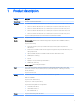
1 Product description Category Description Product Name HP ZBook x2 Detachable Workstation Processors ● Intel® Core™ i7-8650U 1.90-GHz (turbo up to 4.20-GHz) quad core processor (8.0-GB L3 cache, 15-W) ● Intel Core i7-8550U 1.80-GHz (turbo up to 4.00-GHz) quad core processor (8.0-GB L3 cache, 15-W) ● Intel Core i7-7600U 2.80-GHz (turbo up to 3.90-GHz) dual core processor (4.0-GB L3 cache, 15-W) ● Intel Core i5-8250U 1.60-GHz (turbo up to 3.40-GHz) quad core processor (6.
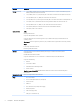
Category Description Storage (continued) ● 1-TB, 2280.M2, Peripheral Component Interconnect Express (PCIe-3×4), Non-Volatile Memory Express (NVMe), Double-Speed (DS) solid-state drive ● 1-TB, 2280.M2, PCIe-3×4, SuperSpeed (SS), HP Z Turbo Drive solid-state drive with triple-level cell (TLC) ● 512-GB, 2280.
Category Description Keyboard/pointing devices Backlit Bluetooth capable Charged through the micro-USB port ClickPad requirements: Power requirements ● Image sensor clickpad ● Glass with chemical-etched surface ● Gestures enabled by default (2-finger scrolling, 2-finger zoom/pinch) ● Taps enabled as default Support for a 4-cell, 70-WHr, 4.55-AHr, Li-ion battery Support for a 65-W, USB Type-C, 3-pin, non-PFC, AC adapter Support for a 1.00-m power cord with a C5 connector in 6 countries/regions.
2 Getting to know your tablet This chapter provides details about the tablet components, where they're located, and how they work. Locating hardware To find out what hardware is installed on the tablet: ▲ Type device manager in the taskbar search box, and then select the Device Manager app. A list displays all the devices installed on the tablet. For information about system hardware components and the system BIOS version number, press fn+esc (select products only).
Right side Item (1) Icon Component Description Battery light When AC power is connected: ● White: The battery charge is greater than 90 percent. ● Amber: The battery charge is from 0 to 90 percent. ● Off: The battery is not charging When AC power is disconnected (battery not charging): ● Blinking amber: The battery has reached a low battery level. When the battery has reached a critical battery level, the battery light begins blinking rapidly.
Item (6) Icon Component Description Memory card reader (continued) 1. Hold the card label up, with the connectors facing the tablet. 2. Insert the card into the memory card reader, and then press in on the card until it is firmly seated. To remove a card: ▲ Press in on the card, and then remove it from the memory card reader. (7) Fingerprint reader (select products only) Allows a fingerprint logon to Windows®, instead of a password logon. (8) Vents Enable airflow to cool internal components.
Left side Item (1) Icon Component Description Audio-out (headphone)/Audio-in (microphone) jack Connects optional powered stereo speakers, headphones, earbuds, a headset, or a television audio cable. Also connects an optional headset microphone. This jack does not support optional standalone devices. WARNING! To reduce the risk of personal injury, adjust the volume before putting on headphones, earbuds, or a headset.
Item Icon Component Description (5) Security cable slot (continued) NOTE: The security cable is designed to act as a deterrent, but it may not prevent the tablet from being mishandled or stolen. (6) Kickstand access tab Provides access to lift the kickstand away from the back of the tablet. (7) Kickstand Provides stability and a variety of viewing angles. (8) Vents Enable airflow to cool internal components.
Front NOTE: This tablet has HP Quick Keys. These keys provide quick access to app shortcuts, and they can be customized to perform the most common key commands with the push of a single button. Item Component Description (1) HP Quick Key customizable button Press the button to perform the customized action. The default action is Reference, which displays the interactive Virtual Desktop overlay for the customizable buttons and optional pen.
Front (continued) NOTE: This tablet has HP Quick Keys. These keys provide quick access to app shortcuts, and they can be customized to perform the most common key commands with the push of a single button. Item Component Description (6) HP Quick Key customizable button Press the button to perform the customized action. There are up to three actions, which depend on the Mode selected. Use the HP Quick Key Mode Select button to choose the mode. The HP Quick Key Mode lights show which Mode is active.
Front (continued) NOTE: This tablet has HP Quick Keys. These keys provide quick access to app shortcuts, and they can be customized to perform the most common key commands with the push of a single button. Item Component Description (11) Cameras (select products only) Allow you to video chat, record video, and record still images. To use your camera, see the User’s Guide. Some cameras also allow a facial recognition logon to Windows, instead of a password logon.
Bottom Item Component Description (1) Alignment posts (2) Connect to the alignment posts on the keyboard base. (2) Docking connector Connects the tablet to the keyboard base. Item Component Description (1) Vents Enable airflow to cool internal components. Rear NOTE: The tablet fan starts up automatically to cool internal components and prevent overheating. It is normal for the internal fan to cycle on and off during routine operation.
Keyboard base components The tablet supports a keyboard. This section provides information about the features of the keyboard. TouchPad Item Component Description (1) TouchPad zone Reads finger gestures to move the pointer or activate items on the screen. (2) Near Field Communications (NFC) tapping area and antenna* Allows you to wirelessly share information when you tap it with an NFC-enabled device. (3) Left TouchPad click area Functions like the left button on an external mouse.
Lights Item Component Description (1) Caps lock light On: Caps lock is on, which switches the keys to all capital letters. (2) Microphone mute light ● Amber: Microphone sound is off. ● Off: Microphone sound is on. (3) 14 Icon Num lock light Chapter 2 Getting to know your tablet On: Num lock is on.
USB port Item Component Description (1) Micro USB port Connects a micro USB cable (purchased separately), that can be used to supply power to the keyboard and, if needed, charge the keyboard battery. NOTE: The keyboard battery charges automatically when the keyboard is connected to the tablet using the docking connector.
Optional HP ZBook x2 Pen Item Component Description (1) Tip/removable nib Draws on the screen. Increased pressure applied to the tip results in wider or darker lines, depending on the software app. The nib is removable. NOTE: Felt and POM tips are included with the pen. To remove the nib from the pen, use the nib removal tool or pen case provided. NOTE: For optimum performance, always store the pen in the pen case.
3 Illustrated parts catalog NOTE: HP continually improves and changes product parts. For complete and current information on supported parts for your tablet, go to http://partsurfer.hp.com, select your country or region, and then follow the on-screen instructions. Labels The labels on the tablet provide information that may be needed when troubleshooting system problems or travelling internationally with the tablet.
Component Description (2) Serial number (3) Product identification (The SKU# that is regionalized #ABA, #ABM) (4) Warranty period (5) 2D bar code that has serial number and product identification information stored Component Description (1) Model name (select products only) (2) Product number (3) Serial number (4) Warranty period The labels on the pen provide information that may be needed when troubleshooting problems or replacing the pen.
Component Description (3) Spare part number (4) Batch number Tablet components Tablet components 19
20 Item Component Spare part number (1) Display panel assembly (14.
Item (14) Component Spare part number Equipped with an Intel Core i5-8250U 1.60-GHz (turbo up to 3.40-GHz) quad core processor (6.0GB L3 cache, 15-W), an Intel GT2 Integrated Graphics subsystem with UMA video memory, and the Windows 10 operating system L03240-601 Equipped with an Intel Core i5-8250U 1.60-GHz (turbo up to 3.40-GHz) quad core processor (6.
Miscellaneous parts Component Spare part number AC adapter: 90-W AC adapter (PFC, S-3P, 4.5-mm) 710413-001 65-W HP Smart Adapter (non-PFC, EM, 4.5-mm) 714657-001 65-W AC adapter (non-PFC, S-3P, 4.
Component Spare part number For use in Switzerland L03264-BG1 For use in Taiwan L03264-AB1 For use in Thailand L03264-281 For use in Turkey L03264-141 For use in the United Kingdom L03264-031 For use in the United States L03264-001 Power cord (C5-connector, 1.
4 Removal and replacement preliminary requirements Tools required You will need the following tools to complete the removal and replacement procedures: ● Case utility tool or other flat-bladed, plastic tool ● Flat-bladed screw driver ● Magnetic screw driver ● Phillips P0 screw driver ● Phillips P00 screw driver ● Torx4 screw driver Service considerations The following sections include some of the considerations that you must keep in mind during disassembly and assembly procedures.
Cables and connectors CAUTION: When servicing the tablet, be sure that cables are placed in their proper locations during the reassembly process. Improper cable placement can damage the tablet. Cables must be handled with extreme care to avoid damage. Apply only the tension required to unseat or seat the cables during removal and insertion. Handle cables by the connector whenever possible. In all cases, avoid bending, twisting, or tearing cables.
Grounding guidelines Electrostatic discharge damage Electronic components are sensitive to electrostatic discharge (ESD). Circuitry design and structure determine the degree of sensitivity. Networks built into many integrated circuits provide some protection, but in many cases, ESD contains enough power to alter device parameters or melt silicon junctions. A discharge of static electricity from a finger or other conductor can destroy static-sensitive devices or microcircuitry.
Packaging and transporting guidelines Follow these grounding guidelines when packaging and transporting equipment: ● To avoid hand contact, transport products in static-safe tubes, bags, or boxes. ● Protect ESD-sensitive parts and assemblies with conductive or approved containers or packaging. ● Keep ESD-sensitive parts in their containers until the parts arrive at static-free workstations. ● Place items on a grounded surface before removing items from their containers.
Equipment guidelines Grounding equipment must include either a wrist strap or a foot strap at a grounded workstation. ● When seated, wear a wrist strap connected to a grounded system. Wrist straps are flexible straps with a minimum of one megohm ±10% resistance in the ground cords. To provide proper ground, wear a strap snugly against the skin at all times. On grounded mats with banana-plug connectors, use alligator clips to connect a wrist strap.
5 Removal and replacement procedures This chapter provides removal and replacement procedures for Authorized Service Provider only parts. CAUTION: Components described in this chapter should only be accessed by an authorized service provider. Accessing these parts can damage the tablet or void the warranty. CAUTION: This tablet does not have user-replaceable parts. Only HP authorized service providers should perform the removal and replacement procedures described here.
5. Remove the kickstand (4). Reverse this procedure to install the kickstand. Display panel assembly Description Spare part number Display panel assembly (14.
2. Remove the four Torx4 M2.0×4.2 shoulder screws that secure the display panel assembly to the tablet. 3. Remove the SD card slot blank. 4. Rest and support the tablet on its bottom edge. NOTE: If suction cups are not available, a case utility tool or other flat-bladed, plastic tool can be used to separate the top edges of the display panel and back cover.
5. Attach suction cups to the display panel and the back cover as shown in the following illustration. CAUTION: Use caution when separating the top edge of the display panel assembly from the back cover. The internal component cables are fragile and only allow for a limited range of motion. Failure to follow this caution can result in damage to the internal components, their cables, and the system board.
6. Use the suction cups to separate the top edge of the display panel assembly from the back cover. 7. Remove the suction cups. 8. Position the tablet on its back cover with the bottom edge toward you. 9. Separate the display panel assembly bottom edge from the back cover. 10. Release the retention tape (1) that secures the battery cable to the system board. CAUTION: When disconnecting the battery cable, use the battery cable connector. Do not use the battery cable.
11. Disconnect the battery cable (2) from the system board. 12. Position the tablet with the top edge toward you. 13. Release the zero insertion force (ZIF) connector (1) to which the right QuickKey button board cable is connected, and then disconnect the right QuickKey button board cable from the system board. 14. Release the ZIF connector (2) to which the left QuickKey button board cable is connected, and then disconnect the left QuickKey button board cable from the system board.
15. Release the ZIF connector (3) to which the TouchScreen control board cable is connected, and then disconnect the TouchScreen control board cable from the system board. CAUTION: Before turning the display panel assembly upside down, make sure the work surface is clear of tools, screws, and any other foreign objects. Failure to follow this caution can result in damage to the display panel. 16.
22. Remove the display panel assembly (6). Reverse this procedure to install the display panel assembly.
QuickKey button board Description Spare part number QuickKey button boards (2, includes left and right button boards and cables) L03247-001 Before removing the QuickKey button boards, follow these steps: 1. Shut down the tablet. If you are unsure whether the tablet is off or in Hibernation, turn the tablet on, and then shut it down through the operating system. 2. Disconnect all external devices connected to the tablet. 3.
Display panel cable Description Spare part number Display panel cable (includes extension cable, grounding tape, and double-sided adhesive) L13280-001 Before removing the display panel cable, follow these steps: 1. Shut down the tablet. If you are unsure whether the tablet is off or in Hibernation, turn the tablet on, and then shut it down through the operating system. 2. Disconnect all external devices connected to the tablet. 3.
Fingerprint reader board Description Spare part number Fingerprint reader board (includes cable) L03249-001 Before removing the fingerprint reader board, follow these steps: 1. Shut down the tablet. If you are unsure whether the tablet is off or in Hibernation, turn the tablet on, and then shut it down through the operating system. 2. Disconnect all external devices connected to the tablet. 3. Disconnect the power from the tablet by first unplugging the power cord from the AC outlet. 4.
Battery Description Spare part number 4-cell, 70-WHr, 4.55-AHr, Li-ion battery (includes cable) 856843-855 Before removing the battery, follow these steps: 1. Shut down the tablet. If you are unsure whether the tablet is off or in Hibernation, turn the tablet on, and then shut it down through the operating system. 2. Disconnect all external devices connected to the tablet. 3.
Wireless antenna Description Spare part number Wireless antenna (includes main and auxiliary wireless antenna cables, transceivers, and doublesided adhesive) L03255-001 Before removing the wireless antenna, follow these steps: 1. Shut down the tablet. If you are unsure whether the tablet is off or in Hibernation, turn the tablet on, and then shut it down through the operating system. 2. Disconnect all external devices connected to the tablet. 3.
5. Remove the wireless antenna cables (5) and transceivers. Reverse this procedure to install the wireless antenna.
Front-facing webcam/microphone module Description Spare part number Front-facing webcam/microphone module (includes camera bracket, cables, and double-sided adhesive) L03250-001 Microphone module (includes cable and double-sided adhesive) L03252-001 Before removing the front-facing webcam/microphone module, follow these steps: 1. Shut down the tablet. If you are unsure whether the tablet is off or in Hibernation, turn the tablet on, and then shut it down through the operating system. 2.
Reverse this procedure to install the front-facing webcam/microphone module. Rear-facing webcam module Description Spare part number Rear-facing webcam module (includes cable and double-sided adhesive) L03251-001 Before removing the rear-facing webcam module, follow these steps: 1. Shut down the tablet. If you are unsure whether the tablet is off or in Hibernation, turn the tablet on, and then shut it down through the operating system. 2. Disconnect all external devices connected to the tablet. 3.
HDMI/USB connector board Description Spare part number HDMI/USB port connector board (includes HDMI port, USB port, and cable) L03248-001 Before removing the HDMI/USB port connector board, follow these steps: 1. Shut down the tablet. If you are unsure whether the tablet is off or in Hibernation, turn the tablet on, and then shut it down through the operating system. 2. Disconnect all external devices connected to the tablet. 3.
POGO pin connector cable Description Spare part number POGO pin connector cable (includes POGO connector and double-sided adhesive) L03262-001 Before removing the POGO pin connector cable, follow these steps: 1. Shut down the tablet. If you are unsure whether the tablet is off or in Hibernation, turn the tablet on, and then shut it down through the operating system. 2. Disconnect all external devices connected to the tablet. 3.
System board NOTE: All system board spare part kits include a processor and replacement thermal material. Description Spare part number Equipped with an Intel Core i7-8650U 1.90-GHz (turbo up to 4.20-GHz) quad core processor (8.0-GB L3 cache, 15-W), an NVIDIA Quadro M620 N17M-Q3 graphics subsystem with discrete video memory, and the Windows 10 operating system L13281-601 Equipped with an Intel Core i7-8650U 1.90-GHz (turbo up to 4.20-GHz) quad core processor (8.
6. Remove the battery (see Battery on page 40). 7. Remove the front-facing webcam/microphone module (see Front-facing webcam/microphone module on page 43).
NOTE: The quantity of screws removed in step 6 varies depending on tablet model. Tablet models equipped with a graphics subsystem with discrete memory have six screws. Tablet models equipped with a graphics subsystem with UMA memory have three screws. 6. Remove the six (or three, depending on computer model) Phillips M2.0×5.6 screws (2) that secure the system board to the back cover. 7. Remove the support bracket (3). The support bracket is available in the Bracket Kit, spare part number L03254-001. 8.
10. Remove the system board (3) by sliding it up and to the right at an angle. Reverse this procedure to install the system board.
NOTE: Steps 2 through 4 apply to tablet models equipped with a graphics subsystem with discrete memory. See steps 5 through 7 for fan/heat sink assembly information for tablet models equipped with a graphics subsystem with UMA memory. 2. Disconnect the fan cables (1) from the system board. 3. Loosen the six Phillips captive screws (2) that secure the fan/heat sink assembly to the system board. 4. Remove the fan/heat sink assembly (3).
Tablet models with a graphics subsystem with UMA memory: Thermal paste is used on the processor (1) and the heat sink section (2) that services it. Reverse this procedure to install the fan/heat sink assembly.
RTC battery Description Spare part number RTC battery L03258-001 Before removing the RTC battery, follow these steps: 1. Shut down the tablet. If you are unsure whether the tablet is off or in Hibernation, turn the tablet on, and then shut it down through the operating system. 2. Disconnect all external devices connected to the tablet. 3. Disconnect the power from the tablet by first unplugging the power cord from the AC outlet, and then unplugging the AC adapter from the tablet. 4.
Reverse this procedure to install the RTC battery. Memory module Description Spare part number 16-GB (2400, 1.2-V DDR4) 865396-855 8-GB (2400, 1.2-V DDR4) 862397-855 4-GB (2400, 1.2-V DDR4) 862398-855 Before removing the memory module, follow these steps: 1. Shut down the tablet. If you are unsure whether the tablet is off or in Hibernation, turn the tablet on, and then shut it down through the operating system. 2. Disconnect all external devices connected to the tablet. 3.
3. Spread the retaining tabs (1) on each side of the memory module slot to release the memory module. (The memory module tilts up.) 4. Remove the memory module (2) by pulling it away from the slot at an angle. NOTE: Memory modules are designed with notches to prevent incorrect insertion. Reverse this procedure to install a memory module. Solid-state drive Description Spare part number 1-TB, 2280.M2, PCIe-3×4, NVMe, DS solid-state drive L11069-001 1-TB, 2280.
3. Disconnect the power from the tablet by first unplugging the power cord from the AC outlet, and then unplugging the AC adapter from the tablet. 4. Remove the display panel assembly (see Display panel assembly on page 30), and then remove the following components: a. Front-facing webcam/microphone module (see Front-facing webcam/microphone module on page 43) b. Battery (see Battery on page 40) c. System board (see System board on page 47) Remove the solid-state drive: 1.
3. Disconnect the power from the tablet by first unplugging the power cord from the AC outlet, and then unplugging the AC adapter from the tablet. 4. Remove the display panel assembly (see Display panel assembly on page 30), and then remove the following components: a. Front-facing webcam/microphone module (see Front-facing webcam/microphone module on page 43) b. Battery (see Battery on page 40) c. System board (see System board on page 47) Remove the speakers: 1. Remove the four Phillips M2.0×3.
Hinges Description Spare part number Hinges (2, available in the Kickstand Hinge Kit, includes left and right hinges) L13279-001 Before removing the hinges, follow these steps: 1. Shut down the tablet. If you are unsure whether the tablet is off or in Hibernation, turn the tablet on, and then shut it down through the operating system. 2. Disconnect all external devices connected to the tablet. 3.
6 Tablet Setup (BIOS), TPM, and HP Sure Start Using Tablet Setup Tablet Setup, or Basic Input/Output System (BIOS), controls communication between all the input and output devices on the system (such as disk drives, display, keyboard, mouse, and printer). Tablet Setup includes settings for the types of devices installed, the startup sequence of the tablet, and the amount of system and extended memory. NOTE: Use extreme care when making changes in Tablet Setup.
Restoring factory settings in Tablet Setup NOTE: Restoring defaults will not change the hard drive mode. To return all settings in Tablet Setup to the values that were set at the factory, follow these steps: 1. Start Tablet Setup. See Starting Tablet Setup on page 59. 2. Select Main, and then select Apply Factory Defaults and Exit. NOTE: On select products, the selections may display Restore Defaults instead of Apply Factory Defaults and Exit. 3. Follow the on-screen instructions. 4.
Downloading a BIOS update CAUTION: To reduce the risk of damage to the tablet or an unsuccessful installation, download and install a BIOS update only when the tablet is connected to reliable external power using the AC adapter. Do not download or install a BIOS update while the tablet is running on battery power, docked in an optional docking device, or connected to an optional power source.
Changing the boot order To dynamically choose a boot device for the current startup sequence, follow these steps: 1. Turn off the tablet. Press the power button, quickly press and hold the volume down button until the Startup menu is displayed, and then tap F9 to enter the Boot menu. 2. Select a boot device, press enter, and then follow the on-screen instructions.
7 Using HP PC Hardware Diagnostics (UEFI) HP PC Hardware Diagnostics is a Unified Extensible Firmware Interface (UEFI) that allows you to run diagnostic tests to determine whether the tablet hardware is functioning properly. The tool runs outside the operating system so that it can isolate hardware failures from issues that are caused by the operating system or other software components.
Downloading HP PC Hardware Diagnostics (UEFI) to a USB device NOTE: The HP PC Hardware Diagnostics (UEFI) download instructions are provided in English only, and you must use a Windows tablet to download and create the HP UEFI support environment because only .exe files are offered. There are two options to download HP PC Hardware Diagnostics to a USB device. Download the latest UEFI version 1. Go to http://www.hp.com/go/techcenter/pcdiags. The HP PC Diagnostics home page is displayed. 2.
8 Specifications Metric U.S. Width 36.5 cm 14.5 in Depth 22.7 cm 8.9 in Height 1.3 cm 0.5 in Weight (includes UMA fan/heat sink assemby, two 4-GB memory modules, no webcam, HP Z Turbo Drive solid-state drive, and no fingerprint reader) 1.4 kg 3.1 lbs Width 36.5 cm 14.5 in Depth 22.7 cm 8.9 in Height 1.9 cm 0.7 in Weight (includes UMA fan/heat sink assembly, two 4-GB memory modules, no webcam, HP Z Turbo Drive solid-state drive, no fingerprint reader, and soft keyboard) 1.9 kg 4.
9 Backing up, restoring, and recovering This chapter provides information about the following processes. The information in the chapter is standard procedure for most products. ● Creating recovery media and backups ● Restoring and recovering your system For additional information, refer to the HP Support Assistant app. ▲ Type support in the taskbar search box, and then select the HP Support Assistant app. ‒ or – Select the question mark icon in the taskbar.
You can use Windows tools to create system restore points and create backups of personal information, see Using Windows tools on page 67. ● If your computer does list the Recovery partition and the Windows partition, you can use HP Recovery Manager to create recovery media after you successfully set up the computer. HP Recovery media can be used to perform system recovery if the hard drive becomes corrupted.
Restore and recovery There are several options for recovering your system. Choose the method that best matches your situation and level of expertise: IMPORTANT: ● Windows offers several options for restoring from backup, refreshing the computer, and resetting the computer to its original state. For more information see the Get started app. ▲ ● Not all methods are available on all products. Select the Start button, and then select the Get started app.
IMPORTANT: HP Recovery Manager does not automatically provide backups of your personal data. Before beginning recovery, back up any personal data you want to retain. Using HP Recovery media, you can choose from one of the following recovery options: NOTE: Only the options available for your computer display when you start the recovery process. ● System Recovery—Reinstalls the original operating system, and then configures the settings for the programs that were installed at the factory.
Changing the computer boot order If your computer does not restart in HP Recovery Manager, you can change the computer boot order, which is the order of devices listed in BIOS where the computer looks for startup information. You can change the selection to an optical drive or a USB flash drive. To change the boot order: IMPORTANT: For a tablet with a detachable keyboard, connect the tablet to the keyboard base before beginning these steps. 1. Insert the HP Recovery media. 2.
Removing the HP Recovery partition (select products only) HP Recovery Manager software allows you to remove the HP Recovery partition to free up hard drive space. IMPORTANT: After you remove the HP Recovery partition, you will not be able to perform System Recovery or create HP Recovery media from the HP Recovery partition. So before you remove the Recovery partition, create HP Recovery media; see Creating HP Recovery media (select products only) on page 66.
10 Statement of memory volatility The purpose of this chapter is to provide general information regarding nonvolatile memory in HP Business PCs. This chapter also provides general instructions for restoring nonvolatile memory that can contain personal data after the system has been powered off and the hard drive has been removed. HP Business PC products that use Intel®-based or AMD®-based system boards contain volatile DDR memory.
h. Select the Main menu, and then select Reset BIOS Security to factory default. Click Yes at the warning message. The tablet will reboot. i. During the reboot, press esc while the "Press the ESC key for Startup Menu" message is displayed at the bottom of the screen. NOTE: 2. If the system has a BIOS administrator password, enter the password at the prompt. j. Select the Main menu, select Apply Factory Defaults and Exit, select Yes to save changes and exit, and then select Shutdown. k.
Nonvolatile memory usage Nonvolatile memory type HP Sure Start flash (select models only) Amount (Size) Does this memory store customer data? Does this memory retain data when power is removed? 8 MBytes No Yes What is the purpose of this memory? Provides protected backup of critical System BIOS code, EC firmware, and critical PC configuration data for select platforms that support HP Sure Start.
Nonvolatile memory type Amount (Size) Does this memory store customer data? Does this memory retain data when power is removed? What is the purpose of this memory? How is data input into this memory? How is this memory writeprotected? follow the on-screen instructions. Intel Management 1.5 MBytes or Engine Firmware 7 MBytes (present in only specific ZBook and EliteBook models. For more information, go to http://www.hp.com/ support, and select your country.
Questions and answers 1. How can the BIOS settings be restored (returned to factory settings)? IMPORTANT: Restore defaults does not securely erase any data on your hard drive. See question and answer 6 for steps to securely erase data. Restore defaults does not reset the Custom Secure Boot keys. See question and answer 7 for information about resetting the keys. 2. a.
IMPORTANT: Resetting will result in the loss of information. These steps will not reset Custom Secure Boot Keys. See question and answer 7 for information about resetting the keys. 7. a. Turn on or restart the tablet, and then press esc while the “Press the ESC key for Startup Menu” message is displayed at the bottom of the screen. b. Select Main, and then select Reset BIOS Security to Factory Default. c. Follow the on-screen instructions. d.
11 Power cord set requirements The wide-range input feature of the tablet permits it to operate from any line voltage from 100 to 120 volts AC, or from 220 to 240 volts AC. The 3-conductor power cord set included with the tablet meets the requirements for use in the country or region where the equipment is purchased. Power cord sets for use in other countries and regions must meet the requirements of the country or region where the tablet is used.
Country/region Accredited agency Applicable note number South Korea EK 4 Sweden CEMKO 1 Switzerland SEV 1 Taiwan BSMI 4 The United Kingdom BSI 1 The United States UL 2 1. The flexible cord must be Type HO5VV-F, 3-conductor, 1.0-mm² conductor size. Power cord set fittings (appliance coupler and wall plug) must bear the certification mark of the agency responsible for evaluation in the country or region where it will be used. 2. The flexible cord must be Type SPT-3 or equivalent, No.
12 Recycling When a non-rechargeable or rechargeable battery has reached the end of its useful life, do not dispose of the battery in general household waste. Follow the local laws and regulations in your area for battery disposal. HP encourages customers to recycle used electronic hardware, HP original print cartridges, and rechargeable batteries. For more information about recycling programs, see the HP Web site at http://www.hp.com/recycle.
Index A AC adapter, spare part numbers 22 alignment posts 12 antenna locations 10 removal 41 spare part number 20, 41 audio, product description 2 audio-in jack 7 audio-out jack 7 B back cover removal 30 spare part numbers 21, 30 backups 66 battery removal 40 spare part number 21, 40 battery light 5 BIOS determining version 60 downloading an update 61 updating 60 boot order changing 70 bottom components 12 buttons HP Quick Key customizable 8, 9, 10, 11 HP Quick Key Mode Select 11 pen 16 power 7 volume down
HP Recovery Manager correcting boot problems 70 starting 69 HP Recovery media creating 66 recovery 69 HP Recovery partition recovery 69 removing 71 HP Sure Start 77 J jacks audio-in 7 audio-out 7 headphone 7 microphone 7 K keyboard base components 13 keyboard, product description 3 keyboard, spare part numbers 22 kickstand 6, 8, 12 removal 29 spare part number 21, 29 kickstand access tab 6, 8 Kickstand Hinge Kit, spare part number 21, 58 L left-side components 7 light components 14 lights battery 5 camera 1
recover options 68 recovery discs 67, 69 HP Recovery Manager 68 media 69 starting 69 supported discs 67 system 68 USB flash drive 69 using HP Recovery media 67 recovery media creating 66 creating using HP Recovery Manager 67 recovery partition removing 71 removal/replacement procedures 29 removing personal data from volatile system memory 72 right-side components 5 RTC battery removal 53 spare part number 21, 53 S Screw Kit, spare part number 23 security cable slot 7, 8 security, product description 3 servi