HP StorageWorks 3Gb SAS BL Switch User Guide The HP StorageWorks 3Gb SAS BL Switch (3Gb SAS BL Switch) is a single-wide interconnect module for HP BladeSystem c-Class enclosures. The 3Gb SAS BL Switch is a key component of HP Direct-Connect External SAS Storage for HP BladeSystem Solutions, with firmware and hardware capabilities that enable the connection of external storage and tape devices to HP BladeSystem c-Class enclosures.
Legal and notice information © Copyright 2009 Hewlett-Packard Development Company, L.P. The information contained herein is subject to change without notice. The only warranties for HP products and services are set forth in the express warranty statements accompanying such products and services. Nothing herein should be construed as constituting an additional warranty. HP shall not be liable for technical or editorial errors or omissions contained herein.
Contents 1 Introduction ....................................................................................... 7 Features ..................................................................................................................................... Types of supported devices .......................................................................................................... Shared storage enclosures ...............................................................................................
Power and environmental specifications ....................................................................................... 37 9 Electrostatic discharge ...................................................................... 39 Preventing electrostatic discharge ................................................................................................ 39 Grounding methods to prevent electrostatic discharge ...................................................................
Polish notice ...................................................................................................................... Portuguese notice ............................................................................................................... Romanian notice ................................................................................................................ Slovak notice ..........................................................................................................
Tables 1 Half-height server blades in c3000 device bays .......................................................... 33 2 BL2x220c server blades in c3000 device bays 1–8 .................................................... 33 3 Full-height server blades in c3000 device bays ........................................................... 33 4 Half-height server blades in c7000 device bays 1–8 ................................................... 34 5 Half-height server blades in c7000 device bays 9–16 ..............
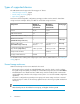
1 Introduction The HP StorageWorks 3Gb SAS BL Switch (3Gb SAS BL Switch) is a single-wide interconnect module for HP BladeSystem c-Class enclosures that enables a server blade with a Smart Array P700m controller to communicate with external SAS storage enclosures and tape devices. Its 3Gb SAS technology delivers high performance, with high data bandwidth up to 300 MB/s per physical link, and is fully compatible with 1.5G SATA technology.
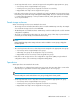
Types of supported devices The 3Gb SAS BL Switch supports the following types of devices: • Shared storage enclosures, page 8 • Zoned storage enclosures, page 9 • Tape devices, page 9 As shown in the following table, configuration (zoning) procedures are the same for shared SAS storage enclosures and tape devices, but differ for zoned SAS storage enclosures: Component Quantity in single-domain environments Quantity in dual-domain environments Servers 16/32 16/32 3Gb SAS BL Switches 1/2 2/4 P700m SA
• Server bays that need access to external storage must be assigned the appropriate zone group. • A server bay can be assigned multiple zone groups. • A switch-port zone group can be assigned to more than one server bay. • Unpopulated server bays can be assigned a zone group. • Disk drives in the storage enclosure are configured into logical units (LUNs) using a storage-enclosure based utility such as the HP Storage Management Utility (SMU).
Introduction
2 Component identification • Off—Normal 1 Unit ID LED • Solid blue—Being identified • Blinking blue—Firmware is being updated • Off—Not powered up 2 Health LED • Solid green—Healthy • Blinking amber—Error, there is a problem with the switch 3 Release button for the locking latch handle.
Component identification
3 Installation procedures 3Gb SAS BL Switch installation procedures include the following steps: • • • • • • • Planning the configuration, page 13 Selecting the interconnect bay, page 13 Installing the switch, page 14 Accessing the switch, page 15 Confirming the firmware version, page 16 Cabling the switch, page 17 Configuring the switch , page 26 NOTE: Most of these steps are also detailed in the HP StorageWorks 3Gb SAS BL Installation instructions that are shipped with the switch.
Installing the switch NOTE: • The 3Gb SAS Switch can be hot-installed in an operational BladeSystem c-Class enclosure. • Make sure that the mezzanine cards are installed in server mezzanine slots that map to the selected BladeSystem c-Class enclosure interconnect bay. • The 3Gb SAS Switch does not have a power on/off button. Power is automatically applied or removed when the switch is installed or removed from the BladeSystem c-Class enclosure.
3. Install the switch in the open interconnect bay. When installed in an operational enclosure, the switch automatically powers up and performs a series of Power On Self Tests. A successful installation is indicated by a green Health LED (Chapter 2 on page 11). If the Health LED is amber or there is no power to the switch, see the "Troubleshooting" section of the HP BladeSystem c-Class enclosure setup and installation guide.
Confirming the firmware version Firmware is pre-installed on each switch in the factory, but updated, alternative, or a preferred version may be available. The following types of firmware are available for the 3Gb SAS BL Switch; choose the firmware type that is best for your environment: • Firmware versions earlier than 2.0.0.0—Single zone support. This firmware version supports connections only to shared SAS storage enclosures such as the MSA2000sa and tape devices such as the MSL G3 tape libraries.
Cabling the switch After confirming the firmware version, connect SAS cables between the switch and the external SAS storage enclosures or tape devices. NOTE: The 3Gb SAS BL Switch uses SAS cables with mini-SAS universal connectors. For a list of supported cables, see the 3Gb SAS BL Switch QuickSpecs. Cabling best practices • When cabling external storage enclosures to the switch, consider which BladeSystem c-Class server bays will need access to the storage.
Cabling examples Examples in this section illustrate just a few of the possible configurations using 3Gb SAS BL Switches. For a wide variety of example configurations using 3Gb SAS BL Switches, see the HP Direct-Connect External SAS Storage for HP BladeSystem Solutions Deployment Guide, available on the BladeSystem Interconnects page of the HP Manuals website http://www.hp.com/support/manuals.
Shared storage—single controller, standard cabling This example illustrates standard cabling for a single-controller controller enclosure. In this configuration, note the following: • Cabling between the single switch and the single controller in an MSA2000sa controller enclosure. • One cable from the switch to the MSA offers single-path connectivity.
Shared storage—dual controller, standard cabling This example illustrates standard cabling for a high-availability configuration. In this configuration, note the following: • Cabling between the two switches and the two controllers in an MSA2000sa controller enclosure. • One cable from each switch to the MSA offers high availability.
Shared storage—dual controller, optimal cabling This example illustrates optimal cabling for a high-performance, high-availability configuration. In this configuration, note the following: • Cabling between the two switches and the two controllers in an MSA2000sa controller enclosure. • An additional cable from each switch to the MSA offers additional availability and performance.
Zoned storage—single domain, standard cabling This example illustrates standard cabling for a single-domain configuration using single-port SATA disk drives. In this configuration, note the following: • One cable from each MDS600 I/O module to the switch offers single-domain connectivity.
Zoned storage—dual domain, standard cabling This example illustrates standard cabling for a high-availability configuration when using dual-port SAS disk drives. In this configuration, note the following: • One cable from each MDS600 I/O module to each switch offers high availability.
Zoned storage—dual domain, wide-port cabling This example illustrates cabling for an optimal high-performance, high-availability configuration when using dual-port SAS disk drives. In this configuration, note the following: • An additional cable from each MDS600 I/O module to an adjacent port on the switch offers additional performance: one cable provides a x4 connection; two cables provide a x8 (wide-port) connection.
Tape enclosure cabling The purpose of this example is to show cabling to a tape library. IMPORTANT: The following illustration shows an MSA2012sa in the configuration, but tape autoloaders and tape libraries are supported with shared SAS storage enclosures and zoned SAS storage enclosures.
Configuring the switch Key configuration tasks include: 1. 2. Enabling or disabling Multi-initiator mode. Creating zone groups: • Switch-port zone groups: For shared SAS storage enclosures and tape libraries. • Drive-bay zone groups: For zoned SAS storage enclosures. 3. 4. Assigning zone groups to servers. Capturing the configuration for safekeeping. HP strongly recommends this step, especially in single-domain configurations. (Available only in the VSM CLI.) NOTE: For firmware versions earlier than 2.
4 Supported software tools Primary configuration and management utilities include: • HP Onboard Administrator overview • HP Virtual SAS Manager overview HP Onboard Administrator overview Onboard Administrator provides a single point from which to view the entire HP BladeSystem c-Class environment and perform basic management tasks on BladeSystem devices, including the 3Gb SAS BL Switch.
HP Virtual SAS Manager overview HP Virtual SAS Manager (VSM) is embedded in the 3Gb SAS BL Switch firmware and is the software application used to create hardware-based zone groups to control access to external SAS storage enclosures and tape devices. HP Virtual SAS Manager (VSM) offers the following key tasks: • • • • • Enter switch parameters Create zone groups Assign zone groups to servers Reset the switch Update firmware The following image is an example of the VSM Maintain tab.
5 Firmware Firmware is managed using the Virtual SAS Manager (VSM) application. For more information, see the HP Virtual SAS Manager user guide, available on the 3Gb SAS BL Switch page of the HP Manuals website http://www.hp.com/support/manuals. As part of a routine system maintenance program, periodically check firmware versions installed on system devices. Updates may include additional features and functions, performance enhancements, support for newly released hardware, or fixes to known issues.
Firmware
6 Troubleshooting Problem Amber LED on Switch Solution • Check OA and VSM for status alerts to identify the problem. • See Chapter 2 on page 11 for LED definitions. Storage not ready during POST (blade) OR Controller lockup during POST Verify the power up sequence and allow sufficient time for each component to power up. Verify cabling from the switch to the storage enclosures. For more information about cabling, see “Cabling the switch” on page 17.
Troubleshooting
7 Internal mappings and cabling recommendations When attaching storage enclosures to SAS ports on the HP 3G SAS BL Switch, use the following cabling guidelines.
c7000 recommendations Table 4 Half-height server blades in c7000 device bays 1–8 If the P700m SAS controller is installed in mezzanine slot 1: If the P700m SAS controller is installed in mezzanine slot 2: • Install 3Gb SAS BL Switches in c7000 interconnect bays 3 and 4 • Attach storage enclosures for these servers to ports 1–4 of the 3Gb SAS BL Switches • Install 3Gb SAS BL Switches in c7000 interconnect bays 5 and 6 or 7 and 8 • Attach storage enclosures for these servers to ports 1–4 of the 3Gb SAS BL
nl nl Table 8 Full-height server blades in c7000 device bays If the P700m SAS controller is installed in mezzanine slot 1: If the P700m SAS controller is installed in mezzanine slot 2: If the P700m SAS controller is installed in mezzanine slot 3: • Install 3Gb SAS BL Switches in c7000 interconnect bays 3 and 4 • Attach storage enclosures for these servers to ports 1–4 of the 3Gb SAS BL Switches • Install 3Gb SAS BL Switches in c7000 interconnect bays 5 and 6 or 7 and 8 • Attach storage enclosures for
Internal mappings and cabling recommendations
8 Technical specifications General specifications Communications nl MPC8343a running at 400MHz processor Data path Dimensions Weight To server blades: 3 Gb SAS x2 To SAS disk drives: 3 Gb SAS x4 To SATA disk drives: 1.5 Gb x4 Height 2.79 cm (1.1 in) Width 19.263 cm (7.584 in) Length 26.792 cm (10.548 in) 2.35 Kg (5.2 lbs) Power and environmental specifications Operating temperature 10° to 35°C (50° to 95°F) at sea level with an altitude derating of 1.0°C per every 305m (1.
Technical specifications
9 Electrostatic discharge Preventing electrostatic discharge To prevent damaging the system, be aware of the precautions you need to follow when setting up the system or handling parts. A discharge of static electricity from a finger or other conductor may damage system boards or other static-sensitive devices. This type of damage may reduce the life expectancy of the device. To prevent electrostatic damage: • Avoid hand contact by transporting and storing products in static-safe containers.
Electrostatic discharge
10 Support and other resources Contacting HP Before you contact HP Be sure to have the following information available before you call or contact HP: • Technical support registration number (if applicable) • Product serial number • Product model name and number • • • • • Product identification number Applicable error message Add-on boards or hardware Third-party hardware or software Operating system type and revision level HP contact information For the name of the nearest HP authorized reseller: • See th
Documentation feedback HP welcomes your feedback. To make comments and suggestions about product documentation, please send a message to storagedocsFeedback@hp.com. All submissions become the property of HP.
Document conventions and symbols Convention Element Blue text: Document conventions and symbols Cross-reference links and e-mail addresses Blue, underlined text: http://www.hp.
Customer self repair HP customer self repair (CSR) programs allow you to repair your StorageWorks product. If a CSR part needs replacing, HP ships the part directly to you so that you can install it at your convenience. Some parts do not qualify for CSR. Your HP-authorized service provider will determine whether a repair can be accomplished by CSR. For more information about CSR, contact your local service provider, or see the CSR website http:// www.hp.com/go/selfrepair.
11 Regulatory compliance notices This section contains regulatory notices for the HP StorageWorks 3Gb SAS BL Switch. Regulatory compliance identification numbers For the purpose of regulatory compliance certifications and identification, this product has been assigned a unique regulatory model number. The regulatory model number can be found on the product nameplate label, along with all required approval markings and information.
radiate radio frequency energy and, if not installed and used in accordance with the instructions, may cause harmful interference to radio communications. However, there is no guarantee that interference will not occur in a particular installation.
Class B equipment This Class B digital apparatus meets all requirements of the Canadian Interference-Causing Equipment Regulations. Cet appareil numérique de la class B respecte toutes les exigences du Règlement sur le matériel brouilleur du Canada.
Japanese notices Korean notices Class A equipment Class B equipment 48 Regulatory compliance notices
BSMI Class A notice Chinese notice Recycling notices English notice Bulgarian notice 3Gb SAS BL Switch User Guide 49
Czech notice Danish notice Dutch notice Estonian notice 50 Regulatory compliance notices
Finnish notice French notice German notice Greek notice 3Gb SAS BL Switch User Guide 51
Hungarian notice Italian notice Latvian notice Lithuanian notice 52 Regulatory compliance notices
Polish notice Portuguese notice Romanian notice Slovak notice 3Gb SAS BL Switch User Guide 53
Spanish notice Swedish notice Turkish notice Türkiye Cumhuriyeti: EEE Yönetmeli ine Uygundur 54 Regulatory compliance notices
Index A accessing the switch, 15 B best practices cabling, 17 zoned cabling, 17 C cabling best practices, 17 examples of, 18 procedures, 17 shared storage, dual controller, 20, 21 shared storage, single controller, 19 tape enclosures, 25 zoned storage, dual domain, 23, 24 zoned storage, single domain, 22 Canadian notice, 46 Chinese notices, 49 configuration, planning for, 13 configuring the storage , configuring the switch, 26 confirming installed firmware version, 16 conventions document, 43 text symbols
J Japanese notices, 48 K Korean notices, 48 L LED definitions, 11 M management tools, 27 managing firmware, 29 mappings, 13 table of, O Onboard Administrator (OA) overview of, 27 overview Onboard Administrator, 27 Virtual SAS Manager (VSM), 28 P planning the configuration, 13 preventing Electrostatic discharge (ESD), 39 R rack stability warning, 44 regulatory compliance Canadian notice, 46 Chinese notices, 49 European Union notice, 47 identification numbers, 45 Japanese notices, 48 Korean notices, 48