Hardware Reference Guide HP Thin Client
Copyright information Warranty © Copyright 2015 HP Development Company, L.P. The information contained herein is subject to change without notice. The only warranties for HP products and services are set forth in the express warranty statements accompanying such products and services. Nothing herein should be construed as constituting an additional warranty. HP shall not be liable for technical or editorial errors or omissions contained herein.
About This Book WARNING! Text set off in this manner indicates that failure to follow directions could result in bodily harm or loss of life. CAUTION: Text set off in this manner indicates that failure to follow directions could result in damage to equipment or loss of information. NOTE: Text set off in this manner provides important supplemental information.
iv About This Book
Table of contents 1 Product features ........................................................................................................................................... 1 Front panel components ....................................................................................................................................... 1 Rear panel components .........................................................................................................................................
Appendix B Electrostatic discharge .................................................................................................................. 31 Preventing electrostatic damage ........................................................................................................................ 31 Grounding methods ............................................................................................................................................. 31 Appendix C Shipping information ........
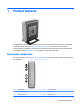
1 Product features This guide describes the features of the thin client. For more information about the hardware and software installed on this thin client, go to http://www.hp.com/go/quickspecs and search for this thin client. Various options are available for your thin client. For more information about some of the available options, go to the HP website at http://www.hp.com and search for your specific thin client. Front panel components For more information, go to http://www.hp.
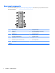
Rear panel components For more information, go to http://www.hp.com/go/ quickspecs/ and search for your specific thin client to find the QuickSpecs. 1 PS/2 mouse port 9 PS/2 keyboard port 2 Parallel port 10 Dual-mode DisplayPort 1.2 ports (4) 3 Serial ports (2) 11 Ethernet RJ-45 port 4 USB 2.
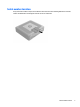
Serial number location Every thin client includes a unique serial number located as shown in the following illustration. Have this number available when contacting HP customer service for assistance.
2 Setup Warnings and cautions Before performing upgrades be sure to carefully read all of the applicable instructions, cautions, and warnings in this guide. WARNING! fire: To reduce the risk of personal injury or equipment damage from electric shock, hot surfaces, or Disconnect the AC power cord from the AC outlet and allow the internal system components to cool before you touch them. Do not plug telecommunications or telephone connectors into the network interface controller (NIC) receptacles.
Connecting the AC power cord 1. Connect the round end of the power supply cord to the power supply connector on the rear of the thin client (1). 2. Use the slot (2) on the side of the retractable AC power cord retention hook to pull the hook out. 3. Press the AC power cord into the retention hook (3) and bundle any excess AC power cord. 4. Plug the female end of the AC power cord into the power supply brick (4). 5. Connect the other end of the AC power cord to an AC outlet (5).
Attaching the stand CAUTION: Unless the thin client is mounted with the HP Quick Release, it must be operated with the stand attached to ensure proper airflow around the thin client. Adjusting the stand The stand can be adjusted into two configurations: square for the horizontal position and rectangular for the vertical position. Take the stand apart by removing the two short pieces connecting the two sides.
● 7. Attach the stand to the right side of the thin client to use it in the horizontal orientation. a. Lay the thin client down with the right side up and locate the two screw holes in the grid on the right side of the thin client. b. Position the stand (1) over the side of the thin client and line up the captive screws in the stand with the screw holes in the thin client. c. Tighten the captive screws (2) securely. Reconnect the AC power cord and then turn the thin client on.
Securing the thin client These thin clients are designed to accept a security cable lock. This cable lock prevents unauthorized removal of the thin client, as well as locking the secure compartment. To order this option, go to the HP website at http://www.hp.com and search for your specific thin client. 1. Locate the cable lock slot on the back panel. 2. Insert the cable lock into the slot, and then use the key to lock it.
To use the HP Quick Release: 1. Using four 10 mm screws included in the mounting device kit, attach one side of the HP Quick Release to the thin client as shown in the following illustration. 2. Using four screws included in the mounting device kit, attach the other side of the HP Quick Release to the device to which you will mount the thin client. Make sure the release lever points upward.
3. Slide the side of the mounting device attached to the thin client (1) over the other side of the mounting device (2) on the device on which you want to mount the thin client. An audible 'click' indicates a secure connection. CAUTION: To ensure proper function of the HP Quick Release and a secure connection of all components, make sure both the release lever on one side of the mounting device and the rounded opening on the other side face upward.
Supported mounting options The following illustrations demonstrate some of the supported mounting options for the mounting bracket.
● 12 Under a desk: Chapter 2 Setup
Supported orientation and placement CAUTION: You must adhere to the HP-supported orientation to ensure your thin clients function properly. Unless the thin client is mounted with the HP Quick Release, it must be operated with the stand attached to ensure proper airflow around the thin client.
● The thin client may be placed under a monitor stand with at least 2.54 cm (1 in) clearance: Non-supported placement HP does not support the following placements for the thin client: CAUTION: devices. Non-supported placement of thin clients could result in operation failure and/or damage to the Thin clients require proper ventilation to maintain operating temperature. Do not block the vents. Do not install the thin client with the I/O ports oriented towards the ground.
● With a monitor on the thin client: Routine thin client care Use the following information to properly care for your thin client: ● Never operate the thin client with the outside panel removed. ● Keep the thin client away from excessive moisture, direct sunlight, and extreme heat and cold. For information about the recommended temperature and humidity ranges for the thin client, see Specifications on page 30. ● Keep liquids away from the thin client and keyboard.
3 Hardware changes Warnings and cautions Before performing upgrades be sure to carefully read all of the applicable instructions, cautions, and warnings in this guide. WARNING! fire: To reduce the risk of personal injury or equipment damage from electric shock, hot surfaces, or Disconnect the AC power cord from the AC outlet and allow the internal system components to cool before you touch them.
3. Turn off the thin client properly through the operating system, and then turn off any external devices. 4. Disconnect the AC power cord from the AC outlet, and disconnect any external devices. CAUTION: Regardless of the power-on state, voltage is always present on the system board as long as the system is plugged into an active AC outlet. You must disconnect the AC power cord to avoid damage to the internal components of the thin client. 5. Remove the stand from the thin client. 6.
Replacing the access panel To replace the access panel: 18 1. Position the access panel on the chassis, approximately 6 mm (.24 in) inside the edge of the chassis. Slide the panel toward the front of the chassis (1) until it locks into place. 2. Move the access panel latch (2) up to secure the access panel. 3.
Locating internal components 1 Memory compartment 4 PCIe riser connector 2 M.2 socket with flash storage module installed 5 M.2 socket with Wi-Fi module installed 3 USB 3.
Removing and replacing the M.2 flash storage module To remove the M.2 flash storage module: 1. Remove/disengage any security devices that prohibit opening the thin client. 2. Remove all removable media, such as USB flash drives, from the thin client. 3. Turn off the thin client properly through the operating system, and then turn off any external devices. 4. Disconnect the AC power cord from the AC outlet, and disconnect any external devices.
11. Pull the screw kit off of the flash storage module and attach it to the replacement flash storage module. 12. Slide the new flash storage module into the M.2 socket on the system board and press the module connectors firmly into the socket. NOTE: A flash storage module can be installed in only one way. Removing and replacing the M.
13. Press the flash storage module down and use a screwdriver to tighten the screw and secure the module to the system board. 14. Replace and latch the access panel, and then reinstall the rear I/O panel. See Removing and replacing the access panel on page 16. 15. Replace the thin client stand. 16. Reconnect the AC power cord and turn on the thin client. 17. Lock any security devices that were disengaged when the thin client access panel was removed.
10. To insert the new battery, slide one edge of the replacement battery under the holder’s lip with the positive side up. Push the other edge down until the clamp snaps over the other edge of the battery (2). 11. Replace and latch the access panel, and then reinstall the rear I/O panel. See Removing and replacing the access panel on page 16. 12. Replace the thin client stand. 13. Reconnect the AC power cord and turn on the thin client. 14.
Replacing a low-profile PCI-Express card An optional low-profile PCI-Express (PCIe) graphics card may be installed in the thin client. A riser card is installed in this thin client by default. WARNING! To reduce the risk of personal injury or equipment damage from electric shock, hot surfaces, or fire, disconnect the AC power cord from the AC outlet and allow the internal system components to cool before you touch them. To install a PCIe card: 1.
13. Press the latch down and move it to the right until it clicks into place (2) to secure the PCIe card. 14. Replace and latch the access panel, and then reinstall the rear I/O panel. See Removing and replacing the access panel on page 16. 15. Replace the thin client stand. 16. Reconnect the AC power cord and turn on the thin client. 17. Lock any security devices that were disengaged when the thin client access panel was removed. Installing an internal USB flash drive There is one USB 3.
9. Align the USB flash drive with the USB port and press the drive firmly into the port until it is securely seated. 10. Replace and latch the access panel, and then reinstall the rear I/O panel. See Removing and replacing the access panel on page 16. 11. Replace the thin client stand. 12. Reconnect the AC power cord and turn on the thin client. 13. Lock any security devices that were disengaged when the thin client access panel was removed.
● 2 Gb and 4 Gb non-ECC memory technologies ● single-sided and double-sided SODIMMS ● SODIMMs constructed with x8 and x16 devices; SODIMMs constructed with x4 SDRAM are not supported NOTE: The system does not operate properly when unsupported SODIMMs are installed. Populating SODIMM sockets There are two SODIMM sockets on the system board. The sockets are labeled DIMM1 and DIMM2.
WARNING! To reduce risk of personal injury from hot surfaces, allow the internal system components to cool before you touch them. 8. Locate the memory compartment on the system board. 9. If a PCIe card is installed, remove it. 10. Loosen the two captive screws (1) securing the memory compartment cover. 11. Lift the memory compartment cover out of the chassis (2). 12.
13. Slide the new SODIMM (1) into the socket at approximately a 30° angle, and then press the SODIMM down (2) so that the latches lock it in place. NOTE: A memory module can be installed in only one way. Match the notch on the module with the tab on the memory socket. 14. Align the memory compartment cover with the two posts and the clips at the base of the compartment, and then set the memory compartment cover (1) over the SODIMMs. TIP: The small clips are pairs.
A Specifications For the latest specifications or additional specifications on the thin client, go to http://www.hp.com/go/ quickspecs/ and search for your specific thin client to find the QuickSpecs. Dimensions Width 65 mm 2.56 in. Depth 220 mm 8.66 in Height (without stand) 240 mm 9.45 In Height (with stand) 250 mm 9.84 in. 10°C to 40°C 50°F to 104°F (max.
B Electrostatic discharge A discharge of static electricity from a finger or other conductor may damage system boards or other staticsensitive devices. This type of damage may reduce the life expectancy of the device. Preventing electrostatic damage To prevent electrostatic damage, observe the following precautions: ● Avoid hand contact by transporting and storing products in static-safe containers. ● Keep electrostatic-sensitive parts in their containers until they arrive at static-free workstations.
C Shipping information Shipping preparation Follow these suggestions when preparing to ship the thin client: 1. Turn off the thin client and external devices. 2. Disconnect the AC power cord from the AC outlet, and then from the thin client. 3. Disconnect the system components and external devices from their power sources, and then from the thin client. 4.
D Accessibility HP designs, produces, and markets products and services that can be used by everyone, including people with disabilities, either on a stand-alone basis or with appropriate assistive devices. Supported assistive technologies HP products support a wide variety of operating system assistive technologies and can be configured to work with additional assistive technologies. Use the Search feature on your device to locate more information about assistive features.
Index A AC power cord connection 5 access panel removing 16 replacing 18 accessibility 33 altitude specifications 30 B battery, replacing 22 C cable lock, installing 8 cautions attaching the stand 6 electric shock 4, 16, 24, 27 HP Quick Release 10 installing SODIMMs 27 removing the battery 22 securing the power cable 5 static electricity 4, 16 thin client orientation 13 thin client placement 14 ventilation 14 components front panel 1 internal 19 rear panel 2 D dimensions 30 E electrostatic discharge 31 F fl
supported assistive technologies 33 supported mounting options 11 supported orientation horizontal 13 supported placement under monitor stand 14 T temperature specifications tower stand 6 30 U USB devices, installing 25 USB ports 2.