Troubleshooting Guide HP t730 Thin Client
© Copyright 2015, 2016 HP Development Company, L.P. The information contained herein is subject to change without notice. Microsoft and Windows are U.S. registered trademarks of the Microsoft group of companies. AMD is a trademark of Advanced Micro Devices, Inc. The information contained herein is subject to change without notice. The only warranties for HP products and services are set forth in the express warranty statements accompanying such products and services.
About This Book WARNING! Text set off in this manner indicates that failure to follow directions could result in bodily harm or loss of life. CAUTION: Text set off in this manner indicates that failure to follow directions could result in damage to equipment or loss of information. NOTE: Text set off in this manner provides important supplemental information.
iv About This Book
Table of contents 1 Product features ........................................................................................................................................... 1 Front panel components ........................................................................................................................................ 1 Rear panel components .........................................................................................................................................
Power-On Sequence ............................................................................................................................................ 35 Resetting the Setup and Power-on passwords ................................................................................................... 36 Power-on diagnostic tests ...................................................................................................................................
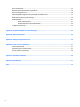
1 Product features This guide describes the features of the thin client. For more information about the hardware and software installed on this thin client, go to http://www.hp.com/go/quickspecs and search for this thin client. Various options are available for your thin client. For more information about some of the available options, go to the HP website at http://www.hp.com and search for your specific thin client. Front panel components For more information, go to http://www.hp.
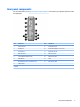
2 Item Component Item Component 2 Flash drive activity LED 5 Headset port 3 USB 2.
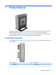
Rear panel components For more information, go to http://www.hp.com/go/ quickspecs/ and search for your specific thin client to find the QuickSpecs. Item Component Item Component 1 PS/2 mouse port 9 PS/2 keyboard port 2 Parallel port 10 Dual-mode DisplayPort 1.2 ports (4) 3 Serial ports (2) 11 Ethernet RJ-45 port 4 USB 2.
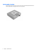
Serial number location Every thin client includes a unique serial number located as shown in the following illustration. Have this number available when contacting HP customer service for assistance.
2 Hardware changes Warnings and cautions Before performing upgrades be sure to carefully read all of the applicable instructions, cautions, and warnings in this guide. WARNING! fire: To reduce the risk of personal injury or equipment damage from electric shock, hot surfaces, or Disconnect the AC power cord from the AC outlet and allow the internal system components to cool before you touch them.
3. Turn off the thin client properly through the operating system, and then turn off any external devices. 4. Disconnect the AC power cord from the AC outlet, and disconnect any external devices. CAUTION: Regardless of the power-on state, voltage is always present on the system board as long as the system is plugged into an active AC outlet. You must disconnect the AC power cord to avoid damage to the internal components of the thin client. 6 5. Remove the stand from the thin client. 6.
Replacing the access panel To replace the access panel: 1. Position the access panel on the chassis, approximately 6 mm (.24 in) inside the edge of the chassis. Slide the panel toward the front of the chassis (1) until it locks into place. 2. Move the access panel latch (2) up to secure the access panel. 3.
Locating internal components 8 Item Component Item Component 1 Memory compartment 4 PCIe riser connector 2 M.2 socket with flash storage module installed 5 M.2 socket with Wi-Fi module installed 3 USB 3.
Removing and replacing the M.2 flash storage module To remove the M.2 flash storage module: 1. Remove/disengage any security devices that prohibit opening the thin client. 2. Remove all removable media, such as USB flash drives, from the thin client. 3. Turn off the thin client properly through the operating system, and then turn off any external devices. 4. Disconnect the AC power cord from the AC outlet, and disconnect any external devices.
11. Pull the screw kit off of the flash storage module and attach it to the replacement flash storage module. 12. Slide the new flash storage module into the M.2 socket on the system board and press the module connectors firmly into the socket. NOTE: A flash storage module can be installed in only one way.
13. Press the flash storage module down and use a screwdriver to tighten the screw and secure the module to the system board. 14. Replace and latch the access panel, and then reinstall the rear I/O panel. See Removing and replacing the access panel on page 5. 15. Replace the thin client stand. 16. Reconnect the AC power cord and turn on the thin client. 17. Lock any security devices that were disengaged when the thin client access panel was removed.
10. To insert the new battery, slide one edge of the replacement battery under the holder’s lip with the positive side up. Push the other edge down until the clamp snaps over the other edge of the battery (2). 11. Replace and latch the access panel, and then reinstall the rear I/O panel. See Removing and replacing the access panel on page 5. 12. Replace the thin client stand. 13. Reconnect the AC power cord and turn on the thin client. 14.
Replacing a low-profile PCI-Express card An optional low-profile PCI-Express (PCIe) graphics card may be installed in the thin client. A riser card is installed in this thin client by default. WARNING! To reduce the risk of personal injury or equipment damage from electric shock, hot surfaces, or fire, disconnect the AC power cord from the AC outlet and allow the internal system components to cool before you touch them. To install a PCIe card: 1.
13. Press the latch down and move it to the right until it clicks into place (2) to secure the PCIe card. 14. Replace and latch the access panel, and then reinstall the rear I/O panel. See Removing and replacing the access panel on page 5. 15. Replace the thin client stand. 16. Reconnect the AC power cord and turn on the thin client. 17. Lock any security devices that were disengaged when the thin client access panel was removed.
Replacing a WLAN module An optional WLAN module may be installed in the thin client. WARNING! To reduce the risk of personal injury or equipment damage from electric shock, hot surfaces, or fire, disconnect the AC power cord from the AC outlet and allow the internal system components to cool before you touch them. To replace a WLAN module: 1. Remove/disengage any security devices that prohibit opening the thin client. 2. Remove all removable media, such as USB flash drives, from the thin client. 3.
11. Remove the WLAN module by pulling the module away from the slot at an angle (3). 12. Insert the WLAN module into the slot (1). 13. Insert the Phillips PM2.0×3.0 screw (2) that secures the WLAN module to the system board. 14. Connect the WLAN antenna cables (3) to the terminals on the WLAN module. NOTE: The number of antenna cables may vary. NOTE: The #1 WLAN antenna cable is connected to the WLAN module Main terminal.
15. Replace and latch the access panel, and then reinstall the rear I/O panel. See Removing and replacing the access panel on page 5. 16. Replace the thin client stand. 17. Reconnect the AC power cord and turn on the thin client. 18. Lock any security devices that were disengaged when the thin client access panel was removed. Installing an internal USB flash drive There is one USB 3.0 flash drive port on the system board. To install a USB flash drive: 1.
12. Reconnect the AC power cord and turn on the thin client. 13. Lock any security devices that were disengaged when the thin client access panel was removed. Installing additional SDRAM system memory The thin client comes with dual channel, double data rate 3 synchronous dynamic random access memory (DDR3/DDR3L) small outline dual inline memory modules (SODIMMs). SODIMMs The memory sockets on the system board can be populated with up to two industry-standard SODIMMs.
Installing SODIMMs CAUTION: You must disconnect the AC power cord and wait approximately 30 seconds for the power to drain before adding or removing memory modules. Regardless of the power-on state, voltage is always supplied to the memory modules as long as the thin client is plugged into an active AC outlet. Adding or removing memory modules while voltage is present may cause irreparable damage to the memory modules or system board. The memory module sockets have gold-plated metal contacts.
11. Lift the memory compartment cover out of the chassis (2). 12. To remove a SODIMM, press outward on the two latches on each side of the SODIMM (1), rotate the SODIMM up, and then pull the SODIMM out of the socket (2).
13. Slide the new SODIMM (1) into the socket at approximately a 30° angle, and then press the SODIMM down (2) so that the latches lock it in place. NOTE: A memory module can be installed in only one way. Match the notch on the module with the tab on the memory socket. 14. Align the memory compartment cover with the two posts and the clips at the base of the compartment, and then set the memory compartment cover (1) over the SODIMMs. TIP: The small clips are pairs.
A Computer Setup (F10) Utility, BIOS Settings Computer Setup (F10) Utilities Use Computer Setup (F10) Utility to do the following: ● Change factory default settings. ● Set the system date and time. ● Set, view, change, or verify the system configuration, including settings for processor, graphics, memory, audio, storage, communications, and input devices. ● Modify the boot order of bootable devices such as solid-state drives or USB flash media devices.
5. Use the arrow (left and right) keys to select the appropriate heading. Use the arrow (up and down) keys to select the option you want, then press enter. To return to the Computer Setup Utilities menu, press esc. 6. To apply and save changes, select File > Save Changes and Exit. ● If you have made changes that you do not want applied, select Ignore Changes and Exit. ● To reset to factory settings, select Apply Defaults and Exit. This option will restore the original factory system defaults.
Computer Setup—File NOTE: 24 Support for specific Computer Setup options may vary depending on the hardware configuration. Option Description System Information Lists: ● Product name ● SKU number ● System Board CT Number ● Processor type ● Processor speed ● Processor stepping ● Cache size (L1/L2) ● Memory size ● Integrated MAC ● System BIOS ● Chassis serial number ● Asset tracking number About Displays copyright notice.
Computer Setup—Storage Option Description Device Configuration Lists all installed BIOS-controlled storage devices. When a device is selected, detailed information and options are displayed. The following options may be presented: Hard Disk: Size, model, firmware version, serial number. Storage Options SATA Emulation CAUTION: SATA emulation changes may prevent access to existing drive data and degrade or corrupt established volumes.
Computer Setup—Security NOTE: Support for specific Computer Setup options may vary depending on the hardware configuration. Table A-1 Computer Setup—Security Option Description Setup Password Allows you to set and enable a setup (administrator) password. NOTE: If the setup password is set, it is required to change Computer Setup options, flash the ROM, and make changes to certain plug and play settings under Windows. Power-On Password Allows you to set and enable a power-on password.
Table A-1 Computer Setup—Security (continued) Option Description System IDs Allows you to set: Tool-less BIOS Update System Security ● Asset tag (18-byte identifier) – A property identification number assigned by the company to the computer. ● Ownership tag (80-byte identifier) Allows you to enable the tool-less BIOS feature, in which BIOS invokes HpBiosUpdate.efi (HpBiosMgmt.efi) and related toolsets in internal/external storage during the last stage of POST.
Table A-1 Computer Setup—Security (continued) Option Description ● Key ownership (HP keys/Customer keys). Lets you change the keys of different owners. Fast Boot (Enable/Disable) – Enable Fast Boot cause system boot by initializing a minimal set of devices which is required to launch active boot option. This option has no effect for BBS boot options. Computer Setup—Power NOTE: Support for specific Computer Setup options may vary depending on the hardware configuration.
Table A-3 Computer Setup—Advanced (for advanced users) (continued) Option Heading ● Bypass F1 Prompt on Configuration Changes (enable/disable). ● Remote Wakeup Boot Source (Local Hard Drive/Remote Server). Allows you to set the source from which the computer gets its boot files when remotely awakened. BIOS Power-On Allows you to set the computer to turn on automatically at a time you specify. Onboard Devices Allows you to set resources for or disable legacy devices.
Changing BIOS Settings from the HP BIOS Configure Utility (HPBCU) Some BIOS settings may be changed locally within the operating system without having to go through the F10 utility. This table identifies the items that can be controlled with this method.
BIOS setting Default value Other values Embedded Security Device(System Security) Disable Enable Reset to Factory Setting Do not reset Reset Measure boot variables/ devices to PCR1 Disable Enable OS management of Embedded Security Device Disable Enable Reset of Embedded Security Device through OS Disable Enable No PPI provisioning Disable Enable Allow PPI policy to be changed by OS Disable Enable Legacy Support Enable Disable (Note: The default value may be varied depends on the OS
BIOS setting Default value Other values Parallel Port IO=378h; IRQ=7; DMA=3 Disable, IO=378h; IRQ=7; DMA=1, IO=278h; IRQ=7; DMA=1, IO=278h; IRQ=7; DMA=3, IO=3BCh; IRQ=7; DMA=1, IO=3BCh; IRQ=7; DMA=3 PCI SERR# Generation Enable Disable PCI VGA Palette Snooping Disable Enable Integrated Graphics Auto Disable, Force UMA Frame Buffer Size 512M 256M, 1G USB Port Configuration Auto Force 2.
Use the following comments to flash a Linux BIOS: ● hptc-bios-flash ImageName Prepares the system to update the BIOS during the next restart. This command automatically copies the files into the correct location and prompts you to restart the thin client. This command requires that the tool-less update option in the BIOS settings is set to Auto. You can use hpt-bios-cfg to set the toolless update option in the BIOS. ● hptc-bios-flash –h Displays a list of options.
B Diagnostics and troubleshooting LEDs Table B-1 Power and IDE Flash Activity LEDs LED Status Power LED Off When the unit is plugged into the wall socket and the Power LED is off, the unit is powered off. However, the network can trigger a Wake On LAN event in order to perform management functions. Power LED On Displays during boot sequence and while the unit is on.
Wake-on LAN Wake-on LAN (WOL) allows a computer to be turned on or resumed from sleep or hibernation state by a network message. You can enable or disable WOL in Computer Setup using the S5 Maximum Power Savings setting. To enable or disable WOL: 1. Turn on or restart the computer. 2. Press either esc or F10 while the “Press the ESC key for Startup Menu” message is displayed at the bottom of the screen.
Resetting the Setup and Power-on passwords You can reset the Setup and Power-on passwords as follows: 1. Turn off the computer and disconnect the power cord from the power outlet. 2. Remove the side access panel and the metal side cover. 3. Remove the password jumper from the system board header labeled PSWD/E49. 4. Replace the metal side cover and the side access panel. 5. Connect the computer to AC power, and then turn on the computer. 6.
Interpreting POST diagnostic front panel LEDs and audible codes This section covers the front panel LED codes as well as the audible codes that may occur before or during POST that do not necessarily have an error code or text message associated with them. WARNING! When the computer is plugged into an AC power source, voltage is always applied to the system board.
Table B-3 Diagnostic front panel LEDs and audible codes (continued) Activity Red Power LED flashes six times, once every second, followed by a two second pause. Beeps stop after fifth iteration but LEDs continue until problem is solved. Beeps 6 Possible Cause Pre-video graphics error. Recommended Action 3. Replace third-party memory with HP memory. 4. Replace the system board. For systems with a graphics card: 1. Reseat the graphics card. 2. Replace the graphics card. 3.
POST numeric codes and text messages This section covers those POST errors that have numeric codes associated with them. The section also includes some text messages that may be encountered during POST. NOTE: The computer will beep once after a POST text message is displayed on the screen. Table B-4 Numeric Codes and Text Messages Control panel message Description Recommended action 103-System Board Failure DMA or timers. 1. Clear CMOS. 2. Remove expansion boards. 3. Replace the system board.
Table B-4 Numeric Codes and Text Messages (continued) Control panel message Description Recommended action 512-Chassis, Rear Chassis, or Front Chassis Fan not Detected Chassis, rear chassis, or front chassis fan is not connected or may have malfunctioned. 1. Reseat chassis, rear chassis, or front chassis fan. 2. Reseat fan cable. 3. Replace chassis, rear chassis, or front chassis fan. 1. Reseat front chassis fan. 2. Reseat fan cable. 3. Replace front chassis fan.
Troubleshooting Basic troubleshooting If the thin client is experiencing operating problems or will not power on, review the following items. Table B-5 Power-on troubleshooting Issue Procedures The thin client unit is experiencing operating problems. Ensure that the following connectors are securely plugged into the thin client unit: The thin client unit does not power on. 1. Verify that the power supply is good by installing it on a known working unit and testing it.
Diskless (No-Flash) unit troubleshooting This section is only for those units that do not have ATA Flash capability. Because there is no ATA Flash in this model the boot priority sequence is: ● USB device ● PXE 1. When the unit boots, the monitor should display the following information: Table B-6 Diskless unit troubleshooting Item Information Action MAC Address NIC portion of the system board is OK If no MAC Address, the system board is at fault. Contact the Call Center for service.
Configuring a PXE server NOTE: All PXE software is supported by authorized service providers on a warranty or service contract basis. Customers who call the HP Customer Service Center with PXE issues and questions should be referred to their PXE provider for assistance. Additionally, refer to the following: – For Windows 2008 R2: http://technet.microsoft.com/en-us/library/7d837d88-6d8e-420c-b68fa5b4baeb5248.aspx – For Windows 2012: http://technet.microsoft.com/en-us/library/jj648426.
C Using HP ThinUpdate to restore the image HP ThinUpdate allows you to download images and add-ons from HP, capture an HP thin client image, and create bootable USB flash drives for image deployment. HP ThinUpdate is preinstalled on some HP thin clients, and it is also available as an add-on at http://www.hp.com/support (search for the thin client model and see the Drivers & software section of the support page for that model).
D Device management The t730 includes a license for HP Device Manager and has a Device Manager agent pre-installed. HP Device Manager is a thin client optimized management tool used to manage the full life cycle of HP thin clients to include Discover, Asset Management, Deployment and Configuration. For more information on HP Device Manager, please visit www.hp.com/go/hpdm. If you wish to manage the t730 with other management tools such as Microsoft SCCM or LANDesk, go to www.hp.
E Adding an Image Restore Tool 1. Ensure that the boot order is set to use the Network as the first boot device. 2. Ensure that IBR.exe (Image Restore) and Flash.dd are stored in the same directory on the server. (e.g., c:\program files\altiris\express\deployment server\images) 3. From the Altiris Deployment Server Console, click File > New > Job . 4. Enter a unique name for the job that you will use to deploy the original thin client image. 5. Click the name of the new job. 6.
F Power cord set requirements The power supplies on some computers have external power switches. The voltage select switch feature on the computer permits it to operate from any line voltage between 100-120 or 220-240 volts AC. Power supplies on those computers that do not have external power switches are equipped with internal switches that sense the incoming voltage and automatically switch to the proper voltage.
Country-specific requirements Additional requirements specific to a country are shown in parentheses and explained below. 48 Country Accrediting Agency Country Accrediting Agency Australia (1) EANSW Italy (1) IMQ Austria (1) OVE Japan (3) METI Belgium (1) CEBC Norway (1) NEMKO Canada (2) CSA Sweden (1) SEMKO Denmark (1) DEMKO Switzerland (1) SEV Finland (1) SETI United Kingdom (1) BSI France (1) UTE United States (2) UL Germany (1) VDE 1.
G Statement of Volatility Thin Client products typically have three types of memory devices namely, RAM, ROM, and Flash memory devices. Data stored in the RAM memory device will be lost once the power is removed from the device. RAM devices could be powered by main, aux, or battery power (power states are explained below). Therefore, even when the unit is not connected to an AC outlet, some of the RAM devices could be powered by battery power.
6. To clear the Setup or Power-On passwords if set, and clear any other settings, power down the computer and remove the AC power cord and the computer hood. 7. Locate the (blue/green) two pin password jumper on header E49 (labeled PSWD) and remove it. 8. Remove AC power, wait ten seconds until the unit AC power has drained out, then press the clear CMOS button. (This is usually a yellow push button, labeled CMOS). 9. Replace the hood and AC power cord and turn the computer on.
H Specifications For the latest specifications or additional specifications on the thin client, go to http://www.hp.com/go/ quickspecs/ and search for your specific thin client to find the QuickSpecs. Item Value Value Width 65 mm 2.56 in. Depth 220 mm 8.66 in Height (without stand) 240 mm 9.45 In Height (with stand) 250 mm 9.84 in. 10°C to 40°C 50°F to 104°F (max.
Index A access panel removing 5 replacing 7 adding an image restore tool 46 altitude specifications 51 audible codes 37 B basic troubleshooting 41 battery, replacing 11 beep codes 37 BIOS updating 32 C cautions electric shock 5, 13, 15, 19 installing SODIMMs 19 removing the battery 11 static electricity 5 changing BIOS settings in the REPSETUP utility 30 components front panel 1 internal 8 rear panel 3 country power cord set requirements 48 D diagnostics and troubleshooting 34 dimensions 51 disabling/enabli
location 17 maximum size 17 W Wake-on LAN (WOL) 35 warnings burn 5, 13, 15, 17, 19 electric shock 5, 11, 13, 15 grounding plug 5 NIC receptacles 5 websites HP 1 wireless card, replacing 15 WLAN module, replacing 15 Index 53