HP 3PAR StoreServ File Controller Administrator Guide Abstract This document describes how to install, configure, and maintain the HP 3PAR StoreServ File Controller and is intended for system administrators. For the latest version of this guide, go to http://www.hp.com/support/manuals. Under storage, select NAS Systems and then select HP 3PAR StoreServ File Controller.
© Copyright 2012, 2013 Hewlett-Packard Development Company, L.P. Confidential computer software. Valid license from HP required for possession, use or copying. Consistent with FAR 12.211 and 12.212, Commercial Computer Software, Computer Software Documentation, and Technical Data for Commercial Items are licensed to the U.S. Government under vendor's standard commercial license. The information contained herein is subject to change without notice.
Contents 1 HP 3PAR StoreServ File Controller ................................................................8 Features..................................................................................................................................8 Hardware components..............................................................................................................8 HP 3PAR StoreServ File Controller hardware components..........................................................
Network adapter teaming........................................................................................................31 Management tools..................................................................................................................31 HP Systems Insight Manager...............................................................................................31 Management Agents..........................................................................................................
File Server Resource Manager..................................................................................................54 Quota management...........................................................................................................55 File screening management.................................................................................................55 Storage reports..................................................................................................................
Creating NFS share resources.........................................................................................69 Shadow copies in a cluster..................................................................................................69 Extend a LUN in a cluster....................................................................................................69 MSNFS administration on a server cluster..............................................................................
Warranty information..............................................................................................................92 Glossary....................................................................................................93 Index.........................................................................................................
1 HP 3PAR StoreServ File Controller The HP 3PAR StoreServ File Controller enables simplified file and application storage. This reduces your cost of ownership by simplifying management, increasing resource utilization, centralizing growth, and protecting data. Features The HP 3PAR StoreServ File Controller provides the following advantages: • Efficiently maximizing resources through file and data management without increasing costs.
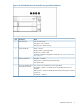
Figure 2 HP HP 3PAR StoreServ File Controller front panel LEDs and buttons Item 1 Description Status NIC status LED Off = No network link Solid green = Link to network Flashing green = Network activity 2 System health LED Green = Normal Flashing amber = System degraded Flashing red = System critical To identify components in degraded or critical state, see “Systems Insight Display LEDs” (page 11).
Figure 3 HP 3PAR StoreServ File Controller rear panel components 1. PCIe slots 1–3 (top to bottom) 2. PCIe slots 4–6 (top to bottom) 3. Power supply 1 (PS1) 4. PS1 power connector 5. PS2 power connector 6. Power supply 2 (PS2) 7. USB connectors (4) 8. Video connector 9. iLO connector 10. Serial connector 11.
Item 4 Description Status NIC activity LED Green = Activity exists Flashing green = Activity exists Off = No activity exists 5 NIC link LED Green = Link exists Off = No link exists Drive LED definitions The following figure shows the drive LEDs. These LEDs are located on all HP ProLiant hot plug hard drives. Figure 5 Drive LEDs Item 1 2 3 4 LED Status Definition Locate Solid blue The drive is being identified by a host application.
Figure 6 Systems Insight Display LEDs Item Description Status 1 Power cap Off = System is in standby, or no cap is set. Solid green = Power cap applied 2 NIC link/activity Solid green = Network link Flashing green = Network link and activity Off = No link to network. If the power is off, view the rear panel RJ-45 LEDs for status.
Table 1 Systems Insight Display LEDs and internal health LED combinations (continued) Systems Insight Display LED and color Health LED System power LED Status • Processor X is unsupported. • ROM detects a failed processor during POST. Amber Green Processor in socket X is in a pre-failure condition. Red Green One or more DIMMs have failed. Amber Green DIMM in slot X is in a pre-failure condition. Over temp (amber) Amber Green The Health Driver has detected a cautionary temperature level.
NOTE: Windows Storage Server 2012 Standard Edition is installed in Server with a GUI mode by default. You can switch to Server Core Installation mode; however, Server Core Installation mode is only supported on an HP 3PAR StoreServ File Controller when the operating environment does not require user interaction (such as in a data center). Any activity that requires the use of a GUI must be done in Server with a GUI mode.
2 Installing and configuring the storage system Setup overview The HP 3PAR StoreServ File Controller comes preinstalled with the Microsoft Windows Storage Server 2012 Standard Edition operating system with Microsoft iSCSI Software Target and a Microsoft Cluster Service (MSCS) license included. Verify the kit contents Remove the contents, ensuring that you have all of the following components. If components are missing, contact HP technical support.
Connect to the storage system Use either the direct attach or remote management method to connect to the storage system. IMPORTANT: Only the direct attach and remote management access methods can be used to install the storage system. After the storage system installation process is complete and the server’s IP addresses have been assigned, you can then additionally use the remote desktop method to access the storage system.
Configure the storage system The HP Initial Configuration Tasks (ICT) window launches automatically at logon. Use the ICT to perform setup tasks such as setting the time zone, network configuration, changing the computer name, joining a domain, creating a virtual disk, and provisioning storage. For more information on any of these tasks, click the help icon for the appropriate task group in the ICT window. NOTE: Microsoft Storage Spaces are not supported on HP 3PAR StoreServ File Controller.
to creating the cluster. The Validate and Create the Cluster wizard uses the following logic to assign LUNs: • ◦ The smallest LUN that is larger than 500 MB will be used as the quorum disk in the cluster. ◦ Any additional LUNs will be assigned to the file server that will be created. ◦ If you want to create a file server when the cluster is created, provision an additional LUN.
the storage system is deployed into a domain environment, user and group information is stored on the domain. • Configuring event notification. • Using Ethernet NIC teaming (optional)—Use Windows Server Manager to configure and monitor Ethernet network interface controller (NIC) teams in a Windows-based operating system. These teams provide options for increasing fault tolerance and throughput.
Updating the storage provider cache The storage provider cache is used by the HP 3PAR StoreServ File Controller to improve the efficiency of storage provisioning operations. After the initial SMI-S provider registration, the cache must be refreshed. Execute the following command in an elevated PowerShell command window: Update-StorageProviderCache –DiscoveryLevel full.
NOTE: Transitioning to Server Core mode disables the OEM-Appliance-OOBE feature. After transitioning back to Server with a GUI mode, you must manually enable this feature by executing the following command: PS C:\Users\Administrator>dism /online /enable-feature /featurename:OEM-Appliance-OOBE Then, install HP ICT from C:\hpnas\Components\ManagementTools.
3 Administration tools HP 3PAR StoreServ File Controller systems include several administration tools to simplify storage system management tasks. Microsoft Windows Storage Server 2012 administration tools Microsoft Windows Storage Server 2012 operating systems provide a user interface for initial server configuration, unified storage system management, simplified setup and management of storage and shared folders, and iSCSI targets.
Administrators can use the File and Storage Services role to setup and manage multiple file servers and their storage by using Server Manager or Windows PowerShell. Some of the specific applications include the following: • Use Data Deduplication to reduce the disk space requirements of your files, saving money on storage. • Use iSCSI Target Server to create centralized, software-based, and hardware-independent iSCSI disk subsystems in storage area networks (SANs).
Print Management Use Print Management to view and manage printers and print servers in your organization. You can use Print Management from any computer running Windows Storage Server 2012, and you can manage all network printers on print servers running Windows 2000 Server, Windows Server 2003, Windows Storage Server 2003, Windows Storage Server 2003 R2, Windows Storage Server 2008, Windows Storage Server 2008 R2, or Windows Storage Server 2012.
4 Storage management overview This chapter provides an overview of some of the components that make up the storage structure of the storage system. Storage management elements Storage is divided into four major divisions: • Physical storage elements • Logical storage elements • File system elements • File sharing elements Each of these elements is composed of the previous level's elements.
Figure 7 Storage management process example Physical storage elements The lowest level of storage management occurs at the physical drive level. Minimally, choosing the best disk carving strategy includes the following policies: • Analyze current corporate and departmental structure. • Analyze the current file server structure and environment. • Plan properly to ensure the best configuration and use of storage.
Arrays See Figure 8 (page 27). With an array controller installed in the system, the capacity of several physical drives (P1–P3) can be logically combined into one or more logical units (L1) called arrays. When this is done, the read/write heads of all the constituent physical drives are active simultaneously, dramatically reducing the overall time required for data transfer. NOTE: Depending on the storage system model, array configuration may not be possible or necessary.
Table 2 Summary of RAID methods RAID 0 Striping (no fault tolerance) RAID 1+0 Mirroring RAID 5 Distributed Data Guarding RAID 6 (ADG) Maximum number of hard N/A drives N/A 14 Storage system dependent Tolerant of single hard drive failure? No Yes Yes Yes Tolerant of multiple simultaneous hard drive failures? No If the failed No drives are not mirrored to each other Yes (two drives can fail) Online spares Further protection against data loss can be achieved by assigning an online spare (or ho
span multiple LUNs. You can use the Windows Disk Management utility to convert disks to dynamic and back to basic and to manage the volumes residing on dynamic disks. Other options include the ability to delete, extend, mirror, and repair these elements. Partitions Partitions exist as either primary partitions or extended partitions.
File system elements File system elements are composed of the folders and subfolders that are created under each logical storage element (partitions, logical disks, and volumes). Folders are used to further subdivide the available file system, providing another level of granularity for management of the information space. Each of these folders can contain separate permissions and share names that can be used for network access. Folders can be created for individual users, groups, projects, and so on.
Network adapter teaming Network adapter teaming is software-based technology used to increase a server's network availability and performance. Teaming enables the logical grouping of physical adapters in the same server (regardless of whether they are embedded devices or Peripheral Component Interconnect (PCI) adapters) into a virtual adapter. This virtual adapter is seen by the network and server-resident network-aware applications as a single network connection.
5 File server management This chapter describes the tasks and utilities that play a role in file server management. File services management Information about the storage system in a SAN environment is provided in the SAN Design Reference Guide, located on the HP web site at www.hp.com/go/SDGManuals. Storage management utilities The storage management utilities preinstalled on the storage system include the HP Array Configuration Utility (ACU).
• A single array can contain multiple logical drives of varying RAID settings. • Extending and expanding arrays and logical drives is supported. The HP Array Configuration Utility User Guide is available for download at http://www.hp.com/ support/manuals. Disk Management utility The Disk Management tool is a system utility for managing hard disks and the volumes, or partitions, that they contain.
performance. Because defragmentation consolidates files and folders, it also consolidates the free space on a volume. This reduces the likelihood that new files will be fragmented. Defragmentation for a volume can be scheduled to occur automatically at convenient times. Defragmentation can also be done once, or on a recurring basis. NOTE: Scheduling defragmentation to run no later than a specific time prevents the defragmentation process from running later than that time.
Storage growth may occur in three forms: • Extend unallocated space from the original logical disks or LUNs. • Alter LUNs to contain additional storage. • Add new LUNs to the system. The additional space is then extended through a variety of means, depending on which type of disk structure is in use. Expanding storage Expansion is the process of adding physical disks to an array that has already been configured.
until that virtual disk is created and presented. Therefore, HP recommends that you wait until a virtual disk is created before presenting it to a host. For more information, see the HP P6000 Command View Software Suite User Guide. Expanding storage using the Array Configuration Utility The Array Configuration Utility enables online capacity expansion of the array and logical drive for specific MSA storage arrays, such as the P2000.
Shadow copy planning Before setup is initiated on the server and the client interface is made available to end users, consider the following: • From what volume will shadow copies be taken? • How much disk space should be allocated for shadow copies? • Will separate disks be used to store shadow copies? • How frequently will shadow copies be made? Identifying the volume Shadow copies are taken for a complete volume, but not for a specific directory.
volume instead of the source volume. Remember that when the storage limit is reached, older versions of the shadow copies are deleted and cannot be restored. CAUTION: To change the storage volume, shadow copies must be deleted. The existing file change history that is kept on the original storage volume is lost. To avoid this problem, verify that the storage volume that is initially selected is large enough.
and shadow copies are enabled on it, users cannot access the shadow copies if they traverse from the host volume (where the mount point is stored) to the mounted drive. For example, assume there is a folder F:\data\users, and the Users folder is a mount point for G:\. If shadow copies are enabled on both F:\ and G:\, F:\data is shared as \\server1\data, and G:\data\users is shared as \\server1\users.
Figure 12 Shadow copies stored on a source volume The cache file location can be altered to reside on a dedicated volume separate from the volumes containing files shares. (See Figure 13 (page 40)). Figure 13 Shadow copies stored on a separate volume The main advantage to storing shadow copies on a separate volume is ease of management and performance. Shadow copies on a source volume must be continually monitored and can consume space designated for file sharing.
Enabling and creating shadow copies Enabling shadow copies on a volume automatically results in several actions: • Creates a shadow copy of the selected volume. • Sets the maximum storage space for the shadow copies. • Schedules shadow copies to be made at 7 a.m. and 12 noon on weekdays. NOTE: Creating a shadow copy only makes one copy of the volume; it does not create a schedule. NOTE: After the first shadow copy is created, it cannot be relocated.
1. 2. 3. 4. 5. 6. 7. Access Disk Management. Select the volume or logical drive, then right-click on it. Select Properties. Select the Shadow Copies tab. Select the volume that you want to redirect shadow copies from and ensure that shadow copies are disabled on that volume; if enabled, click Disable. Click Settings. In the Located on this volume field, select an available alternate volume from the list. NOTE: 8. 9. To change the default shadow copy schedule settings, click Schedule. Click OK.
3. Click the Shadow Copies tab. See Figure 14 (page 43). Figure 14 Accessing shadow copies from My Computer Shadow Copies for Shared Folders Shadow copies are accessed over the network by supported clients and protocols. There are two sets of supported protocols, SMB and NFS. All other protocols are not supported, including HTTP, FTP, AppleTalk, and NetWare Shares. For SMB support, a client-side application denoted as Shadow Copies for Shared Folders is required.
SMB shadow copies Windows users can independently access previous versions of files stored on SMB shares by using the Shadow Copies for Shared Folders client. After the Shadow Copies for Shared Folders client is installed on the user's computer, the user can access shadow copies for a share by right-clicking on the share to open its Properties window, clicking the Previous Versions tab, and then selecting the desired shadow copy. Users can view, copy, and restore all available shadow copies.
point-in-time copies of the file or folder contents that users can then open and explore like any other file or folder. Users can view files in the folder history, copy files from the folder history, and so on. NFS shadow copies UNIX users can independently access previous versions of files stored on NFS shares via the NFS client; no additional software is required. Server for NFS exposes each of a share's available shadow copies as a pseudo-subdirectory of the share.
Recovering an overwritten or corrupted file Recovering an overwritten or corrupted file is easier than recovering a deleted file because the file itself can be right-clicked instead of the folder. To recover an overwritten or corrupted file: 1. Right-click the overwritten or corrupted file, and then click Properties. 2. Click Previous Versions. 3. To view the old version, click Open. To copy the old version to another location, click Copy to replace the current version with the older version, click Restore.
1. 2. 3. 4. Create a shadow copy of the source data on the source server (read-only). Mask off (hide) the shadow copy from the source server. Unmask the shadow copy to a target server. Optionally, clear the read-only flags on the shadow copy. The data is now ready to use. Folder and share management The storage system supports several file-sharing protocols, including DFS, NFS, FTP, HTTP, and Microsoft SMB.
Figure 16 Properties screen, Security tab Several options are available on the Security tab: 3. • To add users and groups to the permissions list, click Add. Follow the dialog box instructions. • To remove users and groups from the permissions list, highlight the desired user or group, and then click Remove. • The center section of the Security tab lists permission levels.
Figure 17 Advanced Security settings screen, Permissions tab Other functionality available in the Advanced Security Settings screen is illustrated in Figure 17 (page 49) and includes: 4. • Add a new user or group—Click Add, and then follow the dialog box instructions. • Remove a user or group— Click Remove. • Replace permission entries on all child objects with entries shown here that apply to child objects—This allows all child folders and files to inherit the current folder permissions by default.
Figure 18 User or group Permission Entry screen Another area of the Advanced Security Settings is the Auditing tab. Auditing allows you to set rules for the auditing of access, or attempted access, to files or folders. Users or groups can be added, deleted, viewed, or modified through the Advanced Security Settings Auditing tab.
Figure 19 Advanced Security Settings screen, Auditing tab 5. Click Add to display the Auditing Entry screen. Figure 20 Auditing Entry for New Volume screen 6. Click Select a principal to display the Select User or Group screen.
Figure 21 Select User or Group screen NOTE: 7. 8. 9. 10. Click Advanced to search for users or groups. Select the user or group. Click OK. Select the desired Successful and Failed audits for the user or group. Click OK. NOTE: Auditing must be enabled to configure this information. Use the local Computer Policy Editor to configure the audit policy on the storage system. The Owner tab allows taking ownership of files.
2. 3. If it is also necessary to take ownership of subfolders and files, enable the Replace owner on subcontainers and objects box. Click OK. Share management There are several ways to set up and manage shares. Methods include using Windows Explorer, a command line interface, or Server Manger. NOTE: Select servers can be deployed in a clustered as well as a non-clustered configuration. This chapter discusses share setup for a non-clustered deployment.
This method results in a hierarchical security model where the network protocol permissions and the file permissions work together to provide appropriate security for shares on the device. NOTE: Share permissions and file-level permissions are implemented separately. It is possible for files on a file system to have different permissions from those applied to a share. When this situation occurs, the file-level permissions override the share permissions.
Quota management On the Quota Management node of the File Server Resource Manager snap-in, you can perform the following tasks: • Create quotas to limit the space allowed for a volume or folder and generate notifications when the quota limits are approached or exceeded. • Generate auto quotas that apply to all existing folders in a volume or folder, as well as to any new subfolders created in the future.
6 Cluster administration One important feature of HP 3PAR StoreServ File Controller systems is that they can operate as a single node or as a cluster. This chapter discusses cluster installation and cluster management issues. Cluster overview A failover cluster is a group of independent computers that work together to increase the availability of applications and services. The clustered servers (called nodes) are connected by physical cables and by software.
Resources Hardware and software components that are managed by the cluster service are called cluster resources. Cluster resources have three defining characteristics: • They can be brought online and taken offline. • They can be managed in a cluster. • They can be owned by only one node at a time. Examples of cluster resources are IP addresses, network names, physical disk resources, and file shares. Resources represent individual system components.
service attempts to transfer the group to the next node on the preferred owner's list. If the transfer is successful, the resources are brought online in accordance with the resource dependency structure. The system failover policy defines how the cluster detects and responds to the failure of individual resources in the group. After a failover occurs and the cluster is brought back to its original state, failback can occur automatically based on the policy.
Figure 24 Cluster concepts diagram Sequence of events for cluster resources The 1. 2. 3. 4. 5. sequence of events in the diagram includes: Physical disks are combined into RAID arrays and LUNs. LUNS are designated as basic disks, formatted, and assigned a drive letter via Disk Manager. Physical Disk resources are created for each basic disk inside Failover Cluster Management. Directories and folders are created on assigned drives.
• An IP Address resource is formed in the group and relates to the IP address by which the group's virtual server is identified on the network. • A Network Name resource is formed in the group and relates to the name published on the network by which the group is identified. • The Group is owned by one of the nodes of the cluster, but may transition to the other nodes during failover conditions. The diagram illustrates a cluster containing two nodes. Each node has ownership of one group.
NOTE: The LUN underlying the basic disk should be presented to only one node of the cluster using selective storage presentation or SAN zoning, or having only one node online at all times until the physical resource for the basic disk is established. In preparing for the cluster installation: • All shared disks, including the Quorum disk, must be accessible from all nodes. When testing connectivity between the nodes and the LUN, only one node should be given access to the LUN at a time.
Table 3 Sharing protocol cluster support Protocol Client Variant Cluster Aware (supports failover) Supported on cluster nodes SMB Windows Yes Yes NFS UNIX Yes Yes Linux HTTP Web No Yes FTP Many Yes Yes NCP Novell No Yes AppleTalk Apple No No iSCSI Standards-based iSCSI Yes initiator Yes NOTE: AppleTalk is not supported on clustered disk resources. AppleTalk requires local memory for volume indexing. On failover events, the memory map is lost and data corruption can occur.
• A domain user account for Cluster service (all nodes must be members of the same domain) • Each node should have at least two network adapters—one for connection to the public network and the other for the node-to-node private cluster network. If only one network adapter is used for both connections, the configuration is unsupported. A separate private network adapter is required for HCL certification.
Setting up networks Verify that all network connections are correct, with private network adapters connected to other private network adapters only, and public network adapters connected to the public network. Configuring the private network adapter The following procedures are best practices provided by Microsoft and should be configured on the private network adapter. • On the General tab of the private network adapter, ensure that only TCP/IP is selected.
Configuring shared disks Use the Windows Disk Management utility to configure additional shared disk resources. Verify that all shared disks are formatted as NTFS and are designated as Basic. Additional shared disk resources are automatically added into the cluster as physical disk resources during the installation of cluster services. Verifying disk access and functionality Write a file to each shared disk resource to verify functionality.
The following rules must be followed with geographically dispersed clusters: • A network connection with latency of 500 milliseconds or less ensures that cluster consistency can be maintained. If the network latency is over 500 milliseconds, the cluster consistency cannot be easily maintained. • All nodes must be on the same subnet. Cluster groups and resources, including file shares The Failover Cluster Management tool provides complete online help for all cluster administration activities.
File share resource planning issues SMB and NFS are cluster-aware protocols that support the Active/Active cluster model, allowing resources to be distributed and processed on both nodes at the same time. For example, some NFS file share resources can be assigned to a group owned by a virtual server for Node A and additional NFS file share resources can be assigned to a group owned by a virtual server for Node B. Configuring the file shares as cluster resources provides for high availability of file shares.
• • Map properly. ◦ Valid UNIX users should be mapped to valid Windows users. ◦ Valid UNIX groups should be mapped to valid Windows groups. ◦ Mapped Windows user must have the “Access this computer from the Network privilege” or the mapping will be squashed. ◦ The mapped Windows user must have an active password, or the mapping will be squashed. In a clustered deployment, create user name mappings using domain user accounts.
NOTE: • Physical disk resources usually do not have any dependencies set. • In multi-node clusters it is necessary to specify the node to move the group to. When a cluster group is moved to another node, all resources in that group are moved. • When a physical disk resource is owned by a node, the disk appears as an unknown, unreadable disk to all other cluster nodes. This is a normal condition. When the physical disk resource moves to another node, the disk resource then becomes readable.
MSNFS administration on a server cluster The Microsoft Services for Network File System (NFS) online help provides server cluster information for the following topics: • • • Configuring shared folders on a server cluster ◦ Configuring an NFS share as a cluster resource ◦ Modifying an NFS shared cluster resource ◦ Deleting an NFS shared cluster resource Using Microsoft Services for NFS with server clusters ◦ Understanding how Server for NFS works with server clusters ◦ Using Server for NFS on a
1. 2. 3. 4. Create Create Create Create a dedicated group (if desired). a physical resource (disk) (if required, see note). an IP address resource for the Virtual Server to be created (if required, see note). a Virtual Server Resource (Network Name) (if required, see note). NOTE: If the printer spool resource is added to an existing group with a physical resource, IP address, and virtual server resource, steps 1-4 are not required. 5. 6. Create a Print Spool resource.
The physical process of restarting one of the nodes of a cluster is the same as restarting a storage system in single node environment. However, additional caution is needed. Restarting a cluster node causes all cluster resources served by that node to fail over to the other nodes in the cluster based on the failover policy in place. Until the failover process completes, any currently executing read and write operations will fail.
7 Troubleshooting, servicing, and maintenance The storage system provides several monitoring and troubleshooting options. You can access the following troubleshooting alerts and solutions to maintain the system health: • Notification alerts • System Management Homepage (SMH) • Hardware component LEDs • HP and Microsoft support websites • HP Insight Remote Support software • Microsoft Systems Center Operations Manager (SCOM) and Microsoft websites • HP SIM 6.
go to http://www.hp.com. Search for your specific product or the underlying server platform (for example, ProLiant DL320 Gen8 server) to find specific updates. • HP recommends updating the operating system, software, firmware, and NIC drivers simultaneously (in the same update window) to ensure proper operation of the storage system. Determining the current storage system software version You can find the current version using the registry. From the registry: 1. Log in to the server blade. 2.
3. 4. 5. Navigate to C:\hp\hpsmh\bin and select hpsmhd. Click Open and then click Add. HP System Management Homepage displays in the Allowed Programs and Features window. Select Home/work (Private) and Public and click OK. To access the SMH on another server, enter the following URL: https://:2381 NOTE: Port 2381 may need to be opened in the system’s firewall, if applicable. System Management Homepage main page Figure 25 (page 75) shows the SMH main page.
Overall System Health Status A webapp sets the value of the Overall System Health Status icon by using a predefined heuristic. If no webapp can determine the status, the worst possible status is displayed in the Component Status Summary section. Component Status summary The Component Status Summary section displays links to all subsystems that have a critical, major, minor, or warning status. If there are no critical, major, minor or warning items, the Component Status Summary section displays no items.
The left panel provides links to information about the following items: • Controller Select a storage controller to view its type, status, firmware version, and serial number. • Physical Drives This section provides an overview of all disk drives attached to the controller. Drives are identified and grouped as assigned, unassigned, and spare drives. Each physical drive is listed as a separate entry in the Storage System submenu.
Table 5 Known issues Issue Resolution On some storage systems, a Confirm that the power settings for the storage system ignore the power button momentary press of the power or disable the power button in the system BIOS. button results in an operating system shutdown. There may be errors from DFS and NFS logged in the Event Viewer after the storage system is configured. These errors can be ignored. Mounted data volumes are not remounted after performing a system recovery.
Table 5 Known issues (continued) Issue Resolution Connecting to remote server 169.254.2.111 failed with the following error message: The WinRM client cannot process the request. If the authentication scheme is different from Kerberos, or if the client computer is not joined to a domain, then HTTPS transport must be used or the destination machine must be added to the TrustedHosts configuration setting. Use winrm.cmd to configure TrustedHosts.
Table 6 HP Insight Management CSP WBEM Providers for Windows errors (continued) Error code Description Source Event Log Entry Type Resolution 0x913 Enclosure Provider is unable to parse the input data provided by EM. Fan, Power supply and IO/PCIe Module classes will not work. HP CSP WBEM Providers Warning Check the provider logs for details. Retry query to provider after 3 minutes. Blade classes may give only partial data.
component information (for example, SAS I/O module), use the following links for troubleshooting information: • Download drivers and software—Provides drivers and software for your operating system. • Troubleshoot a problem—Provides a listing of customer notices, advisories, and bulletins applicable for the product or component. • Manuals—Provides the latest user documentation applicable to the product or component. User guides can be a useful source for troubleshooting information.
Removing and replacing hardware components For information on removing and replacing a hardware component, follow the component removal and replacement instructions in the appropriate storage system user guide. The following list identifies the ProLiant model for each HP 3PAR StoreServ File Controller product: • 3830 Gateway Storage: ProLiant DL380p Gen8 The ProLiant documentation is available at: http://www.hp.
8 Storage system recovery This chapter describes how to perform a system recovery. To restore the HP 3PAR StoreServ File Controller system to the factory defaults, see “Restoring the factory image with a DVD or USB flash device” (page 84). System Recovery DVD The System Recovery DVD enables you to install an image or recover from a catastrophic failure. At any time, you may boot from the DVD and restore the server to the factory condition.
Restoring the factory image with a DVD or USB flash device 1. Do one of the following: a. For direct access, attach the SUV cable (supplied with the System) to the port on the front of the server blade you want to recover. Connect a monitor and USB mouse to the SUV cable. Using the remaining USB connector on the SUV cable, connect either a USB DVD drive (and insert the System Recovery DVD) or a bootable USB flash device (prepared with a System Recovery image). b.
13. Enter assign letter= to assign a drive letter to the USB drive (for example, assign letter=U). 14. Enter exit to quit diskpart context commands. 15. Insert the System Recovery DVD into the computer. 16. Using Windows Explorer or a comparable utility, open the DVD so that all contents are visible, including hidden and system files. 17. Select all of the files (including bootmgr) on the DVD. 18. Copy all of the selected files to the root of the USB flash drive.
The installation continues and eventually the server reboots. After the reboot, Windows automatically logs on as the local Administrator, and launches the Initial Configuration Tasks (ICT) window. However, you will not be using the ICT to configure the node. 4. 5. 6. 7. Check the Do not show this window at next logon box in the lower left corner of the window, and close the ICT window. There will be messages warning about inconsistencies between the nodes. Confirm that you wish to close the ICT.
10. To add the recovered server blade to the cluster, log on to the other server (the server that is part of the existing one node cluster) as a domain user. Do not use the Initial Configuration Tasks (ICT) window. Follow the instructions at the following website to add the recovered server to the cluster: http://technet.microsoft.com/en-us/library/cc730998.
9 Support and other resources Contacting HP HP technical support For worldwide technical support information, see the HP support website: http://www.hp.
Rack stability Rack stability protects personnel and equipment. WARNING! To reduce the risk of personal injury or damage to equipment: • Extend leveling jacks to the floor. • Ensure that the full weight of the rack rests on the leveling jacks. • Install stabilizing feet on the rack. • In multiple-rack installations, fasten racks together securely. • Extend only one rack component at a time. Racks can become unstable if more than one component is extended.
10 Documentation feedback HP is committed to providing documentation that meets your needs. To help us improve the documentation, send any errors, suggestions, or comments to Documentation Feedback (docsfeedback@hp.com). Include the document title and part number, version number, or the URL when submitting your feedback.
A Operating system logical drives The logical disks reside on physical drives as shown in Storage system RAID configurations (page 91). IMPORTANT: The first two logical drives are configured for the storage system operating system. The Operating System volume default factory settings can be customized after the operating system is up and running.
B Regulatory information For important safety, environmental, and regulatory information, see Safety and Compliance Information for Server, Storage, Power, Networking, and Rack Products, available at http:// www.hp.com/support/Safety-Compliance-EnterpriseProducts.
Glossary The following glossary terms and definitions are provided as a reference for storage products. Glossary terms ACL Access control list. ADS Active Directory Service. array A synonym of storage array, storage system, and virtual array. A group of disks in one or more disk enclosures combined with controller software that presents disk storage capacity as one or more virtual disks. backups A read-only copy of data copied to media, such as hard drives or magnetic tape, for data protection.
mount point A host's file system path or directory name where a host volume (device) is accessed. NAS Network attached storage. NFS Network file system. The protocol used in most UNIX environments to share folders or mounts. NIC Network interface card. A device that handles communication between a device and other devices on a network. SAN Storage area network. A network of storage devices available to one or more servers. SAS Serial Attached SCSI. SATA Serial Advanced Technology Attachment.
Index A access rights, managing, 67 Accessing the storage system Remote Desktop method, 21 ACL, defining, 53 Array Configuration Utility, 32 array controller, purpose, 27 arrays, defined, 27 B backup, with shadow copies, 46 basic disks, 28, 29 Belarus Kazakhstan Russia EAC marking, 92 C cache file, shadow copies, 39 Certificate of Authenticity (COA), 15 cluster adding new storage, 68 analysis, 65 concepts, 58 concepts, diagram, 59 diagram, 56 dual data paths, 62 geographically dispersed, 65 group, 66 grou
group, cluster, 60 groups, adding to permissions list, 48 OpsMgr see Microsoft Systems Center Operations Manager (SCOM) H P hardware components HP 3PAR StoreServ File Controller, 8 HP Array Configuration Utility, 32 Storage Manager, 32 HP 3PAR StoreServ File Controller hardware components, 8 integrating 3PAR StoreServ system with, 19 HP Initial Configuration Tasks, 17 partitions extended, 29 primary, 29 permissions file level, 47 list adding users and groups, 48 removing users and groups, 48 modifying,
S SAN environment, 32 security auditing, 50 file level permissions, 47 ownership of files, 52 serial number, 15 server power on, 16 Server Core, using, 20 Services for UNIX, 29, 30 setting up overview, 15 setup completion, 18 shadow copies, 30 backups, 46 cache file, 39 defragmentation, 38 described, 36 disabling, 42 file or folder recovery, 45 in a cluster, 69 managing, 39 mounted drives, 39 on NFS shares, 45 on SMB shares, 44 planning, 37 redirecting, 41 scheduling, 41 uses, 36 viewing list, 41 Shadow Cop