HP 3PAR S-Class/T-Class Storage System Physical Planning Manual Abstract This manual provides information that is useful for planning and preparing for the installation of HP 3PAR S-Class and T-Class Storage systems. Use this document in conjunction with theHP 3PAR Systems Assurance and Pre-Installation Site Planning Guide that details specific system configuration and installation information for your storage system and operating site.
© Copyright 2013 Hewlett-Packard Development Company, L.P. The information contained herein is subject to change without notice. The only warranties for HP products and services are set forth in the express warranty statements accompanying such products and services. Nothing herein should be construed as constituting an additional warranty. HP shall not be liable for technical or editorial errors or omissions contained herein. Acknowledgments Microsoft® and Windows ®are U.S.
Contents 1 System Components and Specifications.........................................................5 HP 3PAR Storage System Components.........................................................................................5 S400/S800 HP 3PAR Storage System Specifications.....................................................................7 Physical Specifications..........................................................................................................7 Capacity Specifications..........
Supported Network Topologies............................................................................................37 Shared Network...........................................................................................................37 Private Network............................................................................................................38 TCP/IP Port Assignments..........................................................................................................
1 System Components and Specifications This chapter provides detailed system specifications for the HP 3PAR S-Class and T-Class Storage systems and serves as a quick reference for other relevant specifications that are described in more detail in other chapters of this manual.
Figure 1 The Front of an S-Class or T-Class HP 3PAR Storage System 6 System Components and Specifications
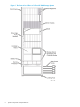
Figure 2 The Rear View of an S-Class or T-Class HP 3PAR Storage System S400/S800 HP 3PAR Storage System Specifications HP 3PAR S400 and S800 Storage systems accommodate up to four or eight controller nodes, respectively. The maximum number of supported drive chassis varies according to the number of controller nodes utilized by the system, the number and type of Fibre Channel adapters that are installed, and the drive chassis connection method being used.
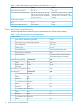
Table 1 S400/S800 Storage System Physical Specifications (continued) S400/S800 Storage System Physical Specifications Maximum Weight per leveling foot 492.5 lbs. 223.4 kg Maximum Load per leveling Foot 157 lbs/sq. in. 11.0 kg/sq. cm S400 Base Configuration 731 lbs. 331.6 kg S800 Base Configuration 792 lbs. 359.2 kg 2 Controller Nodes (fully populated) 160 lbs. 72.5 kg Drive Chassis (fully populated) 175 lbs. 79.4 kg Service Processor 28 lbs. 12.
T400/T800 HP 3PAR Storage System Specifications HP 3PAR T400 and T800 Storage systems accommodate up to four or eight controller nodes, respectively. The maximum number of supported drive chassis varies according to the number of controller nodes utilized by the system, the number and type of Fibre Channel adapters that are installed, and the drive chassis connection method being used. Physical Specifications The following table lists system specifications for the T-Class Storage systems.
Table 4 T400/T800 Storage System Capacity Specifications (continued) Feature RAID 6 data to parity ratios 1 Drive capacities (GB approximate) T400 T800 6:2, 14:2 6:2, 14:2 50 GB SSD, 146 GB 15K FC, 300 GB 15K FC, 400 GB FC, 400 GB SSD, 450 GB 15K FC, 600 GB FC, 1 TB NL, 2 TB NL 50 GB SSD, 146 GB 15K FC, 300 GB 15K FC, 400 GB FC, 400 GB SSD, 450 GB 15K FC, 600 GB FC, 1 TB NL, 2 TB NL 2–16 2–32 not available 0.
Table 5 T-Class Storage System Power Requirements (continued) BTUs/hour 208 160 4 x 450 GB FC Drive Magazines Watts 88 57 BTUs/hour 300 194 4 x 600 GB FC Drive Magazines Watts 73 65 BTUs/hour 249 222 4 x 1 TB NL Drive Magazines Watts 47 32 BTUs/hour 160 109 4 x 2 TB NL SATA Drive Magazines Watts 42 32 BTUs/hour 143 111 Service Processor SuperMicro Watts 260 SuperMicro BTUs/hour (fully populated) 1370 BTUs/hr.
Table 6 Environmental Specifications for HP 3PAR Storage systems (continued) Specification Value 0–3,000 ft (914.4 m) 50 –95° F (10 –35° C) 3,000–10,000 ft (914–3,048 m) Non-operating –40 –203° F (–40– 95° C) 0–40,000 ft (0–12,192 m) Temperature gradient Operating Non-operating 18° F/hr (10° C/hr) 18° F/hr (10° C/hr) Relative humidity NOTE: 20 – 80 percent non-condensing, maximum gradient 10 percent per hour Refer to “Structural/Environmental Considerations” (page 18) for complete details.
2 General Site Planning This chapter provides general recommendations for physical planning and site preparation for installation and operation of the HP 3PAR S-Class and T-Class Storage systems. General Planning Successful installation of HP 3PAR Storage systems requires careful planning and supervision in collaboration with authorized HP representatives. Proper planning will help provide for a more efficient installation and greater reliability, availability, and serviceability.
• Verify that electrical service wiring has been installed at the server’s predetermined location. Refer to the respective product specifications for detailed requirements. • Verify of any additional support equipment is properly installed and operational. At installation time, the HP representative will supervise the delivery and unpacking of the equipment. The representative must also review the crate with the customer to check that the shipping crates have not been tampered with.
package for obvious damage or signs of tampering and notify both HP and the carrier of any issues. Shipping container measurements are as follows: • Cabinet crate (one per 2M rack cabinet): Height: 83 inches (210.8 cm) x Width: 42 in. (106.7 cm) x Depth: 51 in. (129.5 cm) Approximate shipping weight: 1172 lb (531.6 kg) • Drive magazine container (one per 16 drive magazines): 38 in. (96.5 cm) x 34 in. (86.4 cm) x 28 inc.
Figure 4 Front View of the Cabinet Shipping Container The equipment is removed from the front of the container by pulling on two straps that wrap around the cabinet.
Figure 5 Front View of the Container with Ramp Down Acclimatization HP 3PAR Storage systems shipped or stored at extreme temperatures may require time to adjust to operating temperatures before starting up. The maximum acceptable rate of temperature change for a non-operating system is 18° F/hr (10° C/hr). The storage system requires time to acclimatize to new environmental conditions before being powered on.
3 Structural/Environmental Considerations You should consider the following when choosing or designing your facilities for HP 3PAR Storage systems: • Equipment location and layout that allows efficient use, easy maintenance, and future expansion. • Facility construction that provides a suitable operating environment, sufficient power and adequate protection from fire, contamination, or other hazards. • Suitable temperatures and appropriate air quality that is free from environmental contaminants.
Table 10 Raised Floor Specifications Specification Value Flatness tolerance Per 10 ft (3 m) span Overall Less than 0.06 in. (1.5 mm) Less than 0 .10 in. (2.5 mm) Deflection Dynamic Permanent Less than 0.15 in. (3.8 mm) Less than 0.02 in. (0.5 mm) Pedestal assembly load Axial Side At least 5,000 lb (2,268 kg) At least 30 ft-lb (40.7 N-m) Placing each storage system cabinet across two floor tiles is strongly recommended.
However, before placing a cabinet on floor tiles shared with other cabinets or equipment, first verify that the floor panels can tolerate the weight and pressure loads. Maximum weight and pressure loads for storage systems are provided in Table 11 (page 20).
Figure 8 Tile Cutout Specifications WARNING! To prevent potential collapse, loaded floor panels that have cutouts to facilitate cable routing may require additional reinforcement. Anchoring Dimensions for HP 3PAR Storage Systems For some installations, you may want to anchor HP 3PAR Storage systems to the floor for better stability, especially in active seismic locations.
Figure 9 Front View Dimensions for the HP 3PAR Storage System Figure 10 Side View Dimensions for the HP 3PAR Storage System Figure 11 Bottom View Dimensions for the HP 3PAR Storage System 22 Structural/Environmental Considerations
Additional Flooring Recommendations Consider the following recommendations for raised floor installations: • The flooring should be high enough to allow under the floor routing of cables and specified airflow to system air intakes. The recommended minimum floor clearance is 30.5 cm (12 in). An additional 7.6 cm (3 in) should be allowed for cables and connectors. A floor clearance of 46 cm (18 in) is recommended for new construction.
Figure 12 Hot-Aisle/Cold-Aisle Layout Form rows of racks or cabinets perpendicular to air conditioners. This formation facilitates an unobstructed flow of heated air down the aisles to the air conditioner return ducts. Heated air must not be forced to travel over or between the cabinets to get to the air conditioner return ducts. Doing so could heat the air in the cold aisles. Ensure that any free-standing equipment does not allow air to flow between the hot and cold aisles.
NOTE: The S800 and T800 Storage systems have circuit breakers located at both the front and rear of the system. It is necessary to maintain access to both the front and rear circuit breakers. Table 12 Recommended Access Areas for 3PAR Cabinets Cabinet Surface Access Area During Operation Front 36 in (91.4 cm) Rear 30 in (76.2 cm) Left and right sides None NOTE: HP cabinets do not require side access during operation. However, during installation, it is a good practice to allow 3 ft (91.
percent of the load, whereas the dry heat of electronic equipment produces a sensible heat ratio of over 95 percent. Prior to installation, verify that the operating site is equipped with a cooling system that can support all thermal emissions. Use the average and maximum thermal emissions of storage system components listed in Table 14 (page 26) to estimate the cooling requirements for an HP 3PAR Storage system based on a specific system configuration.
recommendations for outside air in comfort air-conditioning are 10 to 15 percent of the airflow, the computer room environment is cleaner and operates more efficiently if outside air is kept below 1 percent of the airflow. Cooling/heating and humidification needs are reduced, and a minimum of contaminated building air is introduced into the installation area. Air Cleanliness Air contaminants can cause equipment malfunction and can damage HP 3PAR Storage systems.
4 Power Requirements This chapter describes the general power requirements for the HP 3PAR Storage systems. Powering HP 3PAR Storage Systems The cabinets used to house the HP 3PAR Storage system components are divided into power domains where each contains a drive cage or controller node and two dedicated power supplies.
NOTE: If a storage system cabinet does not have components installed in the top four bays (bays 0–3, or the highest 16U of the cabinet), the two upper PDUs (PDU 0 and PDU 1) are not used to power the system and need not be connected. Redundant power is still supplied to the lower bays in the cabinet through PDU 2 and PDU 3. Storage server PDUs are equipped with NEMA® L6–30 or IEC 60309 connectors, depending on the region.
Figure 15 Power Banks in the PDU WARNING! To avoid possible injury, damage to storage system equipment, and potential loss of data, do not use the surplus power outlets in the storage system PDUs. Never use outlets in the PDUs to power components that do not belong to the storage system or to power storage system components that reside in other cabinets. Power Cord Connections Storage systems arrive with all internal power cords configured and connected.
NOTE: When routing the power cords through the bottom of the 2 meter cabinet, the usable cord length extends 9.5 to 10 feet away from the cabinet. If routing from the top, approximately 4 feet of the power cord is usable. Electrical Requirements and Limitations Before physically installing an HP 3PAR Storage system, verify that the operating site has the necessary electrical circuitry.
Installing a lightning protection device on the server room power source is recommended when the following conditions exist: • The primary power is supplied by an overhead power service. • The utility company installs lightning protectors on the primary power source. • The area is subject to electrical storms or an equivalent type of power surge. Electrostatic Discharge HP 3PAR Storage systems are susceptible to failure due to electrostatic discharge (ESD).
Figure 17 Front View of the Power Domains Within the Controller Nodes and Drive Chassis Redundant Power 33
Figure 18 Rear View of the Power Domains Within the Controller Nodes and Drive Chassis WARNING! To avoid possible injury, damage to storage system equipment, and potential loss of data, do not use the surplus power outlets in the storage system PDUs. Never use outlets in the PDUs to power components that do not belong to the storage system or to power storage system components that reside in other cabinets.
Figure 19 Redundant Power Configuration Diagram (S800 and T800) Table 15 Redundant Power Configuration (S800 and T800) PDU Number Power Bank AC Cord 0 1 0-L,1-L 0 2 2-R,3-R 1 1 2-L,3-L 1 2 0-R,1-R 2 1 5-R,6-R 2 2 7-L,8-L Redundant Power 35
Table 15 Redundant Power Configuration (S800 and T800) (continued) 36 PDU Number Power Bank AC Cord 3 1 7-R,8-R 3 2 5-L,6-L Power Requirements
5 Network, Cabling and Connectivity This chapter provides information about determining the best network configuration for the HP 3PAR Storage systems being installed at your site, necessary connections and cable routing options. NOTE: The information that follows assumes an established network and discusses how to connect an HP 3PAR Storage system to that network.
Figure 20 Storage System and SP on the Customer Network (Shared Topology) A shared topology requires: • A static IP address and system name for the storage system. • Two Ethernet connections from a switch or hub to the storage system controller nodes. • A static IP address for the SP. • One Ethernet connection from a switch or hub to the SP. • At least one management station on the network segment.
NOTE: It is strongly recommended that the private network segment also have a management station to communicate with the SP. NOTE: This configuration does not permit the SP to communicate with the remote support center.
Table 16 TCP/IP Port Usage Table (continued) Port Usage 5781: HP 3PAR Event Reporting Service Passes unsolicited events from the storage system and is used by the following component: • HP 3PAR Service Processor Flow of Traffic Service Processor <--> storage system Event Service (This port was used for IMC events prior to OS version 2.3.1.
Table 16 TCP/IP Port Usage Table (continued) Port Usage Flow of Traffic HP 3PAR CIM Server 3rd Party CIM Client <--> HP 3PAR Not part of an evaluated configuration CIM Server for Common Criteria 5989: WBEMCIM-XML (HTTPS) (secured) Used for storage system monitoring and configuration over a secured channel by the following component: HP 3PAR CIM Server Not part of an evaluated configuration for Common Criteria 3rd Party CIM Client <-->HP 3PAR CIM Server NOTE: If configured to do so, the storage system
Figure 22 S-Class Controller Node Fibre Channel Ports (Dual-Port Adapters) Figure 23 T-Class Controller Node Fibre Channel Ports (Dual-Port Adapters) 42 Network, Cabling and Connectivity
Fibre Channel adapters can have either two ports (dual-port adapters ) or four ports (quad-port adapters). Required Cables The quantities and lengths of the cables required for storage system installation vary according to the specific storage system and network configuration. Fibre Channel cables are used externally to connect the controller node to the customer switch or host (in the case of a directly connected host).
1 2 To provide redundancy and to permit online software (for example, nodes 0 and 1, nodes 2 and 3, and so To provide redundancy and to permit online software (for example, nodes 0 and 1, nodes 2 and 3, and so • upgrades, both controller nodes in a single horizontal node pair on) must maintain connections to each host server. upgrades, both controller nodes in a single horizontal node pair on) must maintain connections to each host server.
Cable Routing Options Storage system cabinets have both upper and lower access openings available for Fibre Channel cable routing (Figure 24 (page 45)). It is also possible to route network cables and main power cords through specially designated upper and lower openings in the cabinet.
Table 21 SP Connections 46 Connection type Configuration Ethernet For SP: connection from the RJ-45 connector in the ETH 0 port at the rear of the SP to an Ethernet hub or switch ( Figure 24 (page 45) or ???). Modem (optional) Connection from the line serial port at the rear of the SP to an RJ-11 modular telephone outlet.
6 Support and Other Resources Contacting HP For worldwide technical support information, see the HP support website: http://www.hp.
For information about: See: Migrating data from one HP 3PAR storage system to another HP 3PAR-to-3PAR Storage Peer Motion Guide 48 Configuring the Secure Service Custodian server in order to monitor and control HP 3PAR storage systems HP 3PAR Secure Service Custodian Configuration Utility Reference Using the CLI to configure and manage HP 3PAR Remote Copy HP 3PAR Remote Copy Software User’s Guide Updating HP 3PAR operating systems HP 3PAR Upgrade Pre-Planning Guide Identifying storage system compo
For information about: See: Planning for HP 3PAR storage system setup Hardware specifications, installation considerations, power requirements, networking options, and cabling information for HP 3PAR storage systems HP 3PAR 7200, 7400, and 7450 storage systems HP 3PAR StoreServ 7000 Storage Site Planning Manual HP 3PAR StoreServ 7450 Storage Site Planning Manual HP 3PAR 10000 storage systems HP 3PAR StoreServ 10000 Storage Physical Planning Manual HP 3PAR StoreServ 10000 Storage Third-Party Rack Physic
Initializing and using the Service Processor HP 3PAR Service Processor Software User Guide: Service Edition Upgrading the Service Processor HP 3PAR Service Processor Software Upgrade Instructions: Service Edition Troubleshooting the Service Processor HP 3PAR Service Processor Troubleshooting Guide: Service Edition Remotely servicing all storage systems Remotely servicing HP 3PAR storage systems HP 3PAR Secure Service Collector Remote Operations Guide Servicing 7200 and 7400 storage systems Maintaini
Typographic conventions Table 22 Document conventions Convention Element Bold text • Keys that you press • Text you typed into a GUI element, such as a text box • GUI elements that you click or select, such as menu items, buttons, and so on Monospace text • File and directory names • System output • Code • Commands, their arguments, and argument values • Code variables • Command variables Bold monospace text • Commands you enter into a command line interface • Syste
7 Documentation feedback HP is committed to providing documentation that meets your needs. To help us improve the documentation, send any errors, suggestions, or comments to Documentation Feedback (docsfeedback@hp.com). Include the document title and part number, version number, or the URL when submitting your feedback.
A Regulatory information For important safety, environmental, and regulatory information, see Safety and Compliance Information for Server, Storage, Power, Networking, and Rack Products, available at http:// www.hp.com/support/Safety-Compliance-EnterpriseProducts.