
Hardware Reference Guide


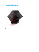
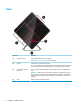
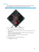
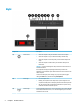
Table Of Contents
- Product features
- Hardware upgrades
- Warnings and cautions
- Preparing for disassembly
- Accessing the tool kit
- Replacing or installing drives
- Removing and replacing the access panel
- Installing system memory
- Installing graphics cards
- Removing the PCI fan
- Installing a system board
- Removing the hard drive fan
- Installing a power supply
- Installing a radiator bracket for liquid cooling
- Cleaning filters
- Electrostatic discharge
- Computer operating guidelines and routine care
- Accessibility
- Index
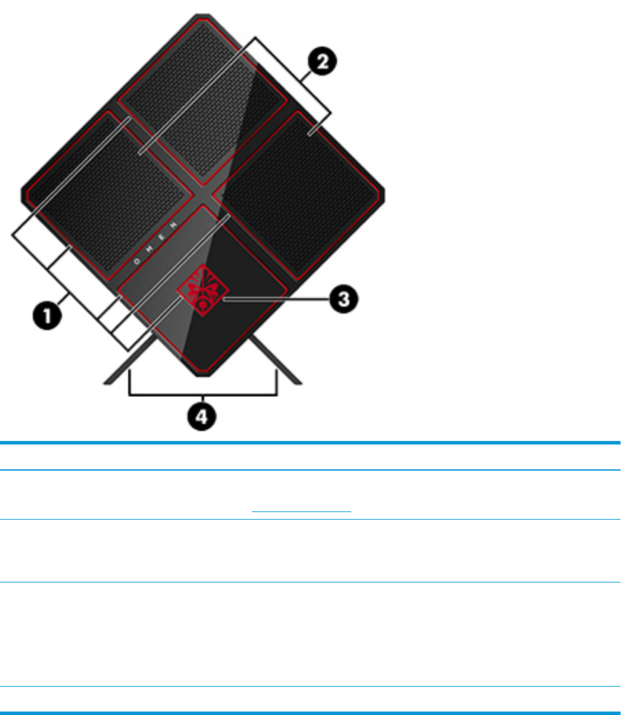
Front
Component Description
(1) Lighted color zones Create unique lighting eects on the computer.
NOTE: See Color zones on page 3 for more information.
(2) Vents (2) Enable airow to cool internal components.
NOTE: The computer fan starts up automatically to cool internal components and prevent
overheating. It is normal for the internal fan to cycle on and o during routine operation.
(3) Tool kit (located under the
logo panel)
Contains a wrench and screws required to install computer components and graphics card
fans.
WARNING! To reduce the risk of serious injury or damage to the equipment, do not open
the chassis cover of any computer containing a 600 W PSU, 750 W PSU, or 1300 W PSU. To
determine if you have a 600 W, 750 W, or 1300 W PSU, refer to the label on the back of the
computer.
(4) Stand Holds the computer in an upright position.
2 Chapter 1 Product features