
HP 640 ProBook G3 Notebook PC & HP 650 ProBook G3 Notebook PC - Maintenance and Service Guide
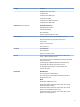
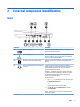
Table Of Contents
- Product description
- External component identification
- Illustrated parts catalog
- Removal and replacement procedures preliminary requirements
- Removal and replacement procedures for Authorized Service Provider parts
- Component replacement procedures
- Service door
- Battery
- Hard drive
- Solid-state drive (select products only)
- WWAN module (select products only)
- WLAN module
- Optical drive
- Keyboard
- Memory
- Hinge cover
- Base enclosure
- System board
- Fan and heat sink assembly
- Optical drive board
- Top cover and TouchPad
- RTC battery
- Speaker
- Power button board
- Fingerprint reader (select products only)
- Smart card reader
- Near Field Communication module
- Audio board
- Serial board
- Display assembly
- Component replacement procedures
- Computer Setup (BIOS), TPM, and HP Sure Start
- Using HP PC Hardware Diagnostics (UEFI)
- Backing up, restoring, and recovering
- Specifications
- Power cord set requirements
- Statement of memory volatility
- Recycling
- Index
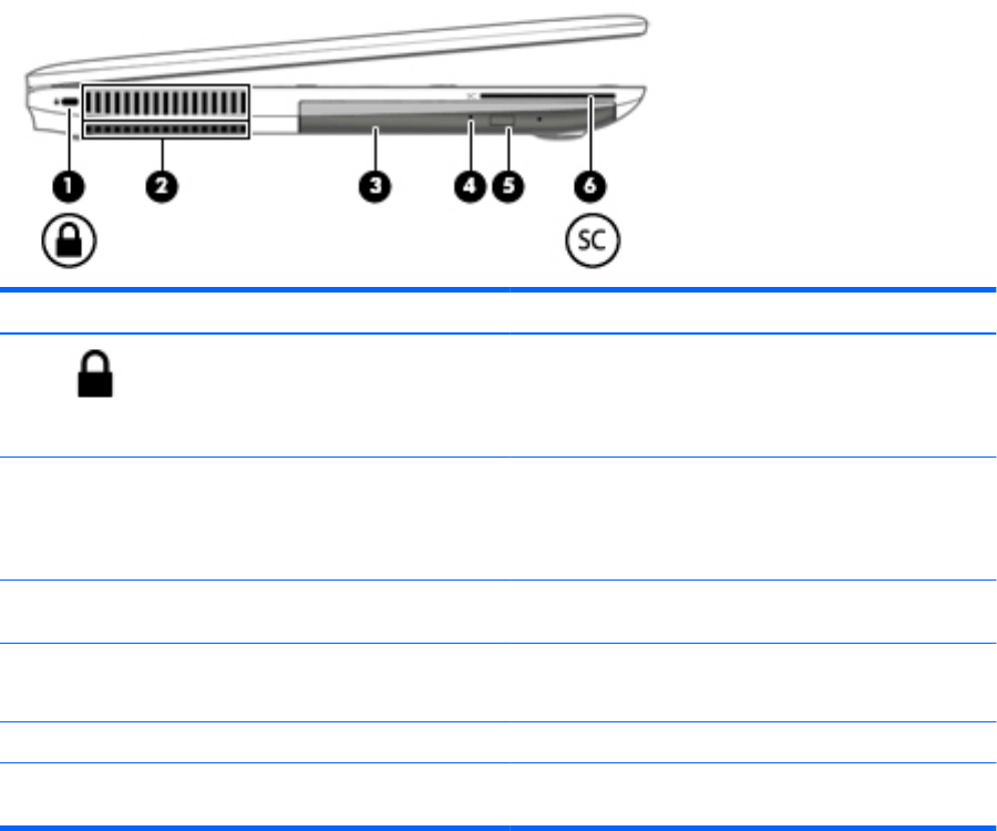
Left
Component Description
(1) Security cable slot Attaches an optional security cable to the computer.
NOTE: The security cable is designed to act as a deterrent, but
it may not prevent the computer from being mishandled or
stolen.
(2) Vent Enables airow to cool internal components.
NOTE: The computer fan starts up automatically to cool
internal components and prevent overheating. It is normal for
the internal fan to cycle on and o during routine operation.
(3) Optical drive (select products only) Depending on your computer model, reads an optical disc or
reads and writes to an optical disc.
(4) Optical drive light (select products only) On: The optical drive is in use.
O: The optical drive is not in use.
(5) Optical drive eject button (select products only) Releases the optical drive disc tray.
(6) Smart card reader (depending on the
conguration)
Supports optional smart cards.
Left 9